


DIY Heat Exchanger Prep

Member

Joined: Aug 2010
Posts: 209
Likes: 2
E55 AMG
When I was looking at the intercooler circuit the other day, it seems like the intercooler has it's circuit completely separate from the radiator. The only thing they have in common is their filling points ( the expansion tank ). The intercooler does NOT seem to circulate water through this expansion tank though once it's full so I really don't see a big benefit in splitting the system unless you're going to install a large reservoir.
Sorry I am just a tad bit confused. Basically there is no benefit in splitting the cooling system in regards to "seperating the fluids" because they dont mix, correct? However the benefit in splitting the system would be due to adding a additional resevoir of larger capacity, correct?
To sum it up, does this mean the method of splitting the cooling system and adding a power steering resevoir is detrimental to cooling because one is reducing resevoir capacity?


MBWorld Fanatic!
Joined: Jun 2010
Posts: 4,173
Likes: 7
From: Puerto Rico
2005 E55 AMG
Sorry I am just a tad bit confused. Basically there is no benefit in splitting the cooling system in regards to "seperating the fluids" because they dont mix, correct? However the benefit in splitting the system would be due to adding a additional resevoir of larger capacity, correct?
To sum it up, does this mean the method of splitting the cooling system and adding a power steering resevoir is detrimental to cooling because one is reducing resevoir capacity?
To sum it up, does this mean the method of splitting the cooling system and adding a power steering resevoir is detrimental to cooling because one is reducing resevoir capacity?
I'm sure the heat transfer from the hot water stuck in the piping to fill the intercooler circuit via the expansion tank will not help, but it should not make a big difference either. But keep in mind that while the heat exchanger DOES NOT cycle water through the expansion tank, IT DOES cycle water through the add-on power steering reserviour when seperated ( al least that's now I imagine it's connected, with an inlet AND outlet ). That means that the power steering system will have more capacity ( even if it's a small amount more ). I doubt it makes a very big difference though.

MBWorld Fanatic!
Joined: Sep 2008
Posts: 3,575
Likes: 8
From: BC
Haters crazy
Reviving this biatch from the dead lol...
Any more info about splitting the system's benefits? As far as I see it, I agree with GT-ER I don't see how splitting the system would benefit when the only thing in common is the fill point, and splits into the 2 systems via the T. Where does it mix?
Has anyone data logged the difference between split and non split? I'm not experiencing any heat soak at this time, wondering if I should even bother. (Already have all the parts)
Also how would you go about bleeding the 2 separate systems?
Thanks

MBWorld Fanatic!
Joined: Apr 2009
Posts: 1,139
Likes: 0
From: Lincoln, NE
2005 SL600, 2016 ES300h, 2012 Hayabusa
I had a tech pull my old pump and there was about a cup of fluid that leaked out of the lower line, shouldn't the line be absolutely full? I have an sl600, not sure if that changes things.
MBWorld Fanatic!
Joined: Apr 2009
Posts: 1,139
Likes: 0
From: Lincoln, NE
2005 SL600, 2016 ES300h, 2012 Hayabusa
Anyone feel like reviving this yet again? I got a bigger HE from speedriven but may consider adding a secondary as well depending on the results. I got their pump and plan to wire it for always on, but I don't have a logger to check my temps. I don't plan to spit the circuits at this point as I don't think there is that much mixing from the factory, I think the bigger factor would be pump/system performance under the pressure that a hot system would create. Feel free to post up any new findings.

Former Vendor of MBWorld
Joined: May 2012
Posts: 290
Likes: 1
From: Toronto
SpeedRiven SL600, ML320CDI
Anyone feel like reviving this yet again? I got a bigger HE from speedriven but may consider adding a secondary as well depending on the results. I got their pump and plan to wire it for always on, but I don't have a logger to check my temps. I don't plan to spit the circuits at this point as I don't think there is that much mixing from the factory, I think the bigger factor would be pump/system performance under the pressure that a hot system would create. Feel free to post up any new findings.
I just took my own SL600 on the track yesterday in 90 degrees heat (ECU/TCU. HE and pump) - no issues.
Igor.
Last edited by AccelToronto; Jun 21, 2012 at 02:35 PM.
MBWorld Fanatic!
Joined: Apr 2009
Posts: 1,139
Likes: 0
From: Lincoln, NE
2005 SL600, 2016 ES300h, 2012 Hayabusa
I haven't got it in yet but I'm hoping to get the setup in this weekend. I was hoping to get some help with wiring and bleeding since the pump has 2 red wires and I'm not 100% sure on bleeding the v12 system
MB World Stories
The Best of Mercedes & AMG

7 Craziest Things AMG Gas Ever Built
Verdad Gallardo
New Electric Mercedes-AMG GT 4-Door Coupe Unveiled: 10 Things You Need to Know
Verdad Gallardo
6 Mercedes Models That Did NOT Age Well (But Are Somehow Still Cool)
Verdad Gallardo
Manual Mercedes? 6 Times Sindelfingen Let Drivers Have All The Fun
Verdad Gallardo
Mercedes SLR McLaren 722 S Is Extremely Rare Example Modified by McLaren
Verdad Gallardo
8 Classic Boxy Mercedes Designs That Have Aged Like Fine Wine
Verdad Gallardo
Flawlessly Restored Mercedes 190E Evo II Heads to Auction
Verdad Gallardo
Electric Mercedes C-Class Unveiled: 11 Things You Need to Know
Verdad Gallardo
Mercedes EQS Gets A Major Update: Everything You Need to Know
Verdad Gallardo

MBWorld Fanatic!
Joined: Mar 2011
Posts: 1,879
Likes: 22
From: Orange County, CA.
one car at a time
We did not have any overheating/power loss issues with just stock HEs and pumps from SpeedRiven. I would try stock install first and, unless you are planning on racing for 2 hours straight, do not think you will have overheating issues. Is there something special about your car that you think will cause overheating with stock SpeedRiven setup ?
I just took my own SL600 on the track yesterday in 90 degrees heat (ECU/TCU. HE and pump) - no issues.
Igor.
I just took my own SL600 on the track yesterday in 90 degrees heat (ECU/TCU. HE and pump) - no issues.
Igor.
I have a lot of logs with the factory setup and the EC h/e and will now run the pump from a switched source and see if that helps. Then I will add a large tank and see what gains were had.
I will post all of the data as there seems to be more opinions than facts....
Last edited by cij911; Sep 4, 2012 at 11:23 AM.
MBWorld Fanatic!


Joined: May 2007
Posts: 6,406
Likes: 140
From: Clearwater Beach, Florida
2016 Cls63s AMG
is this one of the that u guys are using... has some sort of bracket on but not sure if its the correct one
http://www.ebay.com/itm/2007-BMW-E90...e5af1d&vxp=mtr
http://www.ebay.com/itm/2007-BMW-E90...e5af1d&vxp=mtr
MBWorld Fanatic!
Joined: May 2007
Posts: 6,406
Likes: 140
From: Clearwater Beach, Florida
2016 Cls63s AMG

MBWorld Fanatic!

Joined: Dec 2011
Posts: 1,645
Likes: 13
From: tampa florida
19 f-150 limited (w/raptor engine) 06 e55,81SC Targa,08 CLK63 BLK,91 E34 M5
Awesome write up thanks
I'm having Ron Davis make me a secondary front mount heat exchanger which I'll get in a few weeks. Meanwhile I decided to split the intercooler coolant circuit, add a reservoir, and wire the pump to turn on when in accessory mode. I kept my stock pump for now until the heat exchanger arrives, but will swap in a CM30 during that install.
No IAT logging done before and after splitting the circuit since I was going to do it anyway for the new HE. I plan to log temps with this setup and then after I install the HE.
Pics of course....
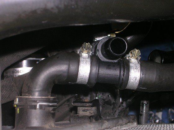
Here are the components for splitting the circuit. Reservoir, mounting bracket, hose clamps, 3/4" hose splice, and 3/4"-5/8" hose splice. I made the extension bracket and tapped it for mounting.

Cut the Oetiker ring style clamps off existing line and remove stock tee. Reconnect hose using 3/4" splice and install new clamps. Install the reducing splice into the intercooler circuit.

Run a 5/8" inch heater hose to the reservoir.

Tighten the mounting bolt on the reservoir. I put a thin rubber washer under the fender washer to help protect the surface and painted the stainless washer black to blend in better. Add coolant, run the pump, and take for a drive to test.

Here's the wire I grabbed for switched power to act as the trigger on the relay I installed for always on pump operations. It was a pain in the butt to find but that wire goes to a relay stuffed in the corner of the fuse box. There might be other options but this worked well for me.

No IAT logging done before and after splitting the circuit since I was going to do it anyway for the new HE. I plan to log temps with this setup and then after I install the HE.
Pics of course....
Here are the components for splitting the circuit. Reservoir, mounting bracket, hose clamps, 3/4" hose splice, and 3/4"-5/8" hose splice. I made the extension bracket and tapped it for mounting.
Cut the Oetiker ring style clamps off existing line and remove stock tee. Reconnect hose using 3/4" splice and install new clamps. Install the reducing splice into the intercooler circuit.
Run a 5/8" inch heater hose to the reservoir.
Tighten the mounting bolt on the reservoir. I put a thin rubber washer under the fender washer to help protect the surface and painted the stainless washer black to blend in better. Add coolant, run the pump, and take for a drive to test.
Here's the wire I grabbed for switched power to act as the trigger on the relay I installed for always on pump operations. It was a pain in the butt to find but that wire goes to a relay stuffed in the corner of the fuse box. There might be other options but this worked well for me.
Super Member
Joined: Nov 2012
Posts: 698
Likes: 16
From: Germany
C215 CL55 AMG, W124 500E, W210 E430, W124 300E
Personally after long long hours of reading and thinking about this idea, i don't think it will make a big difference. I would personally probably add a larger/additional front HE and a stronger pump.
However there is one benefit, you can run much lower antifreeze levels in the IC circuit if you would separate them.

However there is one benefit, you can run much lower antifreeze levels in the IC circuit if you would separate them.

Junior Member
Joined: Dec 2011
Posts: 74
Likes: 0
From: Melbourne Australia
03 E55, HB Torana
Should the BMW power steering res have a breather hole in the cap? And spray water everywhere when the pumps running?
And should the water from the spilt system with trunk tank drain the BMW power steering res when the trunk tanks internal pump is running?
Thanks guys
And should the water from the spilt system with trunk tank drain the BMW power steering res when the trunk tanks internal pump is running?
Thanks guys
Senior Member


Joined: Sep 2011
Posts: 384
Likes: 13
From: Sweden
E55 AMG V8 Kompressor 2004 E 55 AMG Type: 5,439 cc (5.439 L; 331.9 cu in) Supercharged V8 Powe
sry old thread but best so far for the E55
I'm having Ron Davis make me a secondary front mount heat exchanger which I'll get in a few weeks. Meanwhile I decided to split the intercooler coolant circuit, add a reservoir, and wire the pump to turn on when in accessory mode. I kept my stock pump for now until the heat exchanger arrives, but will swap in a CM30 during that install.
No IAT logging done before and after splitting the circuit since I was going to do it anyway for the new HE. I plan to log temps with this setup and then after I install the HE.
Pics of course....
Here are the components for splitting the circuit. Reservoir, mounting bracket, hose clamps, 3/4" hose splice, and 3/4"-5/8" hose splice. I made the extension bracket and tapped it for mounting.

Cut the Oetiker ring style clamps off existing line and remove stock tee. Reconnect hose using 3/4" splice and install new clamps. Install the reducing splice into the intercooler circuit.
Run a 5/8" inch heater hose to the reservoir.

Tighten the mounting bolt on the reservoir. I put a thin rubber washer under the fender washer to help protect the surface and painted the stainless washer black to blend in better. Add coolant, run the pump, and take for a drive to test.

Here's the wire I grabbed for switched power to act as the trigger on the relay I installed for always on pump operations. It was a pain in the butt to find but that wire goes to a relay stuffed in the corner of the fuse box. There might be other options but this worked well for me.

No IAT logging done before and after splitting the circuit since I was going to do it anyway for the new HE. I plan to log temps with this setup and then after I install the HE.
Pics of course....
Here are the components for splitting the circuit. Reservoir, mounting bracket, hose clamps, 3/4" hose splice, and 3/4"-5/8" hose splice. I made the extension bracket and tapped it for mounting.
Cut the Oetiker ring style clamps off existing line and remove stock tee. Reconnect hose using 3/4" splice and install new clamps. Install the reducing splice into the intercooler circuit.
Run a 5/8" inch heater hose to the reservoir.
Tighten the mounting bolt on the reservoir. I put a thin rubber washer under the fender washer to help protect the surface and painted the stainless washer black to blend in better. Add coolant, run the pump, and take for a drive to test.
Here's the wire I grabbed for switched power to act as the trigger on the relay I installed for always on pump operations. It was a pain in the butt to find but that wire goes to a relay stuffed in the corner of the fuse box. There might be other options but this worked well for me.
Any way to get to the pictures?

Super Member
Joined: Jan 2016
Posts: 599
Likes: 120
2004 E55
Search on youtube, there is one or two videos...pretty straight forward. the hard info is in there in txt for sizes of fittings adapters needed.
Not trying to be a D, but if cutting out a T fitting and inserting a barbed fitting then running a tank off the extra line you just free'd up is hard perhaps you should just get it somewhere for the install/splitting of the systems...
Remove the radiator fan, it makes things so much more accessible in this area IMHO
Senior Member
Joined: Sep 2011
Posts: 384
Likes: 13
From: Sweden
E55 AMG V8 Kompressor 2004 E 55 AMG Type: 5,439 cc (5.439 L; 331.9 cu in) Supercharged V8 Powe
[QUOTE=BoostedAero;7099997]Search on youtube, there is one or two videos...pretty straight forward. the hard info is in there in txt for sizes of fittings adapters needed.
Not trying to be a D, but if cutting out a T fitting and inserting a barbed fitting then running a tank off the extra line you just free'd up is hard perhaps you should just get it somewhere for the install/splitting of the systems...
Remove the radiator fan, it makes things so much more accessible in this area IMHO[/QUOTE
YEP
Last edited by SuperChargerE55; May 13, 2017 at 05:12 AM.


