When you click on links to various merchants on this site and make a purchase, this can result in this site earning a commission. Affiliate programs and affiliations include, but are not limited to, the eBay Partner Network.
Plus if you look at the tubes they are awfully small to feed a cylinder {volume} at 6,000 rpm....maybe down low but up top I just don't see it. But again the theory appears to work.....I guess ?? Who knows.
Unrelated but along the same lines sort of with intake volume:
What I am doing,shot in the dark, is having the two intakes Extrude honed to pick up some air flow so I will let you know what that doe's.
Nice, yeah that will be awesome to see your results. My thought process on the cross overs was that the neck of the surge tank is what... 2.5" diameter (I think they are actually closer to 2") is almost 5 square inch area, So even if you pick up only 1" in diameter on the cross overs, combined that's about a 1.6 square inch increase in flow area adding the cross overs.. that's a 30% increase in the flow area going from the 2.5" bottle neck to the 2.5" bottle neck plus two 1" cross overs. And If the bottle neck at the back of the surge tank is only 2" in diameter, that's a 50% increase in flow area! (3.1 sq in area plus the 1..6 sq in from the cross overs)
****, people talk about getting 30+ hp going from 74mm to an 82mm throttle body, that's effectively going from 6.7 sq inch to 8.2 sq inch in area which is only a 22% increase in flow area. Now granted that's on the suction side of the SC not the discharge and I'm sure it is not the same comparison, but that's kind of where my thinking is. The cross overs are small but the overall increase in flow area by adding them is pretty significant I'd say. I bet I could get this done for <100$ at a local machine shop. I would love to see what it actually did haha.
Personally i think extrode honing would really make a good difference and such. Heres my plan and i dont know if it will work or not its just a thought. If one were to just pull off the surge tanks an cut an weld a bigger tank on this would help an then one could port the tubes going to the back side giving them better flow. If this theory holds true then it would lower the work the supercharger has to do an lower heat build up as well as a by product. Hummmmmm if only i had good welding skills lol
Looks like standard straight hose coupler cut to size. Some angled edges would help with the bend in the hose. I would love for this to work. Hopefully someone can complete the monumental task of getting some before after dyno and boost logs one day.
Looks like standard straight hose coupler cut to size. Some angled edges would help with the bend in the hose. I would love for this to work. Hopefully someone can complete the monumental task of getting some before after dyno and boost logs one day.
I'm wondering about the actual pipe not the coupler, I'm guessing 2" aluminum tube from some where? I don't know what material the manifolds actually are. Gotta find a good aluminum welder I think :-P If I end up trying it I will definitely do logs before/after.
Looks like standard straight hose coupler cut to size. Some angled edges would help with the bend in the hose. I would love for this to work. Hopefully someone can complete the monumental task of getting some before after dyno and boost logs one day.
45� Degree coupler cut to size and 2" aluminium pipe. I added an aluminium bend to the silicone coupler (inside) or somewhat, because the slicone contracts under vacuum
On a 55 it would be easier to fit. I would use a 2.5" pipe. but not round rather oval pipe.
Its no science. it takes 2-3 hours to fit including aluminium welding.
I just reached out to a couple local machine shops to get a quote for the work. If I get it done I wont have back to back dyno pulls but I will have back to back 1/4 mile trips(Had a good day yesterday ) and torque pro logs with no other changes
Look forward to it drothgeb !!
I will only do one mod at a time,not for cost but logistics, and decided on the Extrude hone first since doing two things at one time, Extrude/Cross Over, will not give me a fair opinion on what worked and what didn't.
Should have them back tomorrow. I am having two 1.5" crossovers done for a total cross sectional area addition of 3.5sq". The Y necks are 2" diameter with an area of 3.14sq", so the dual 1.5" cross overs should allow full utilization of the opposite side Y pipe. I chose 1.5" because a size down 2x 1.25" tubes only provides a total cross sectional area of 2.5sq" so I figured if the flow potential is there to utilize the other side pipe, the cross overs would still be slightly restrictive at 2x 1.25" (all speculation, the flow may not be needed at all, but we will see!)
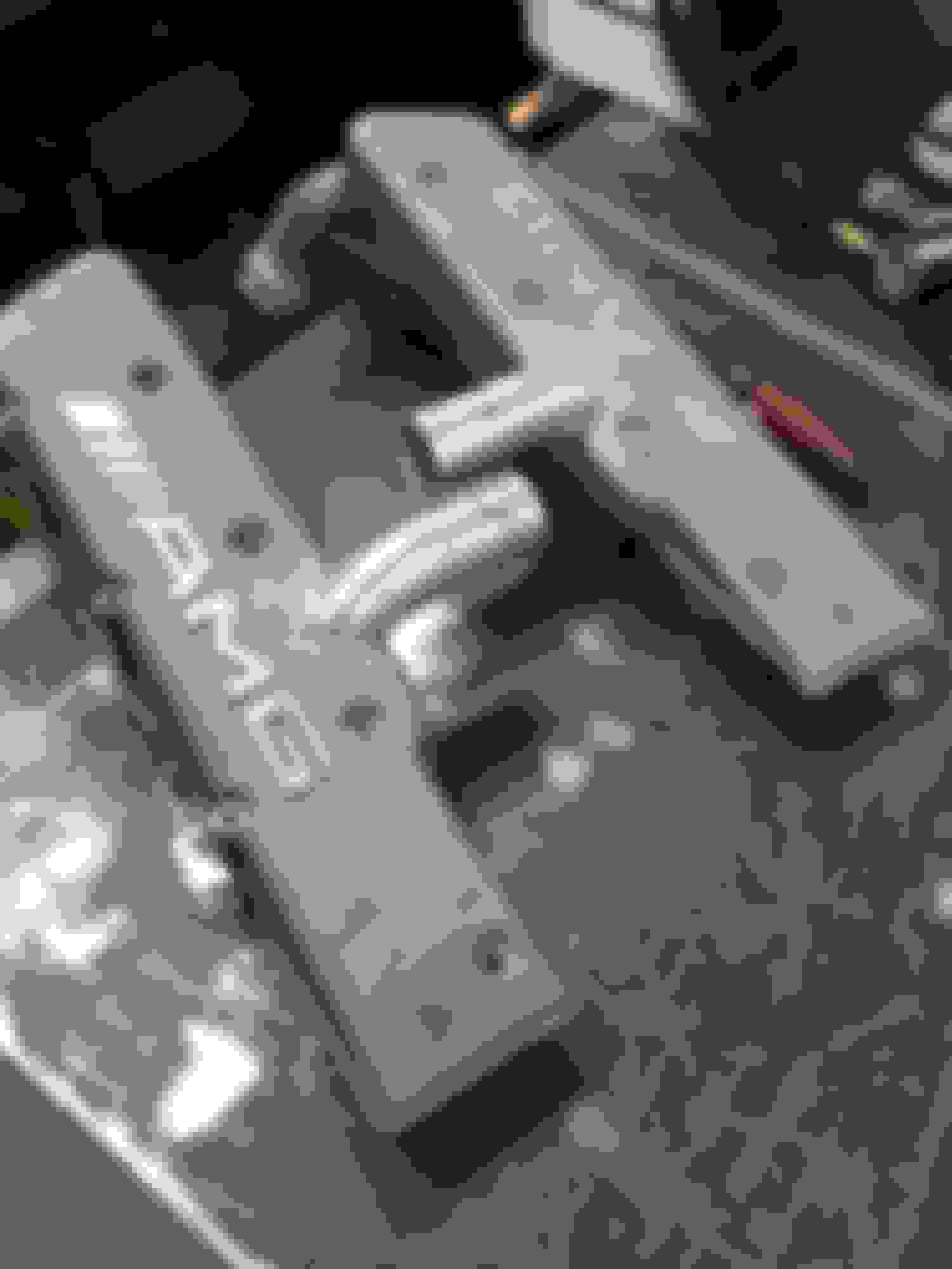
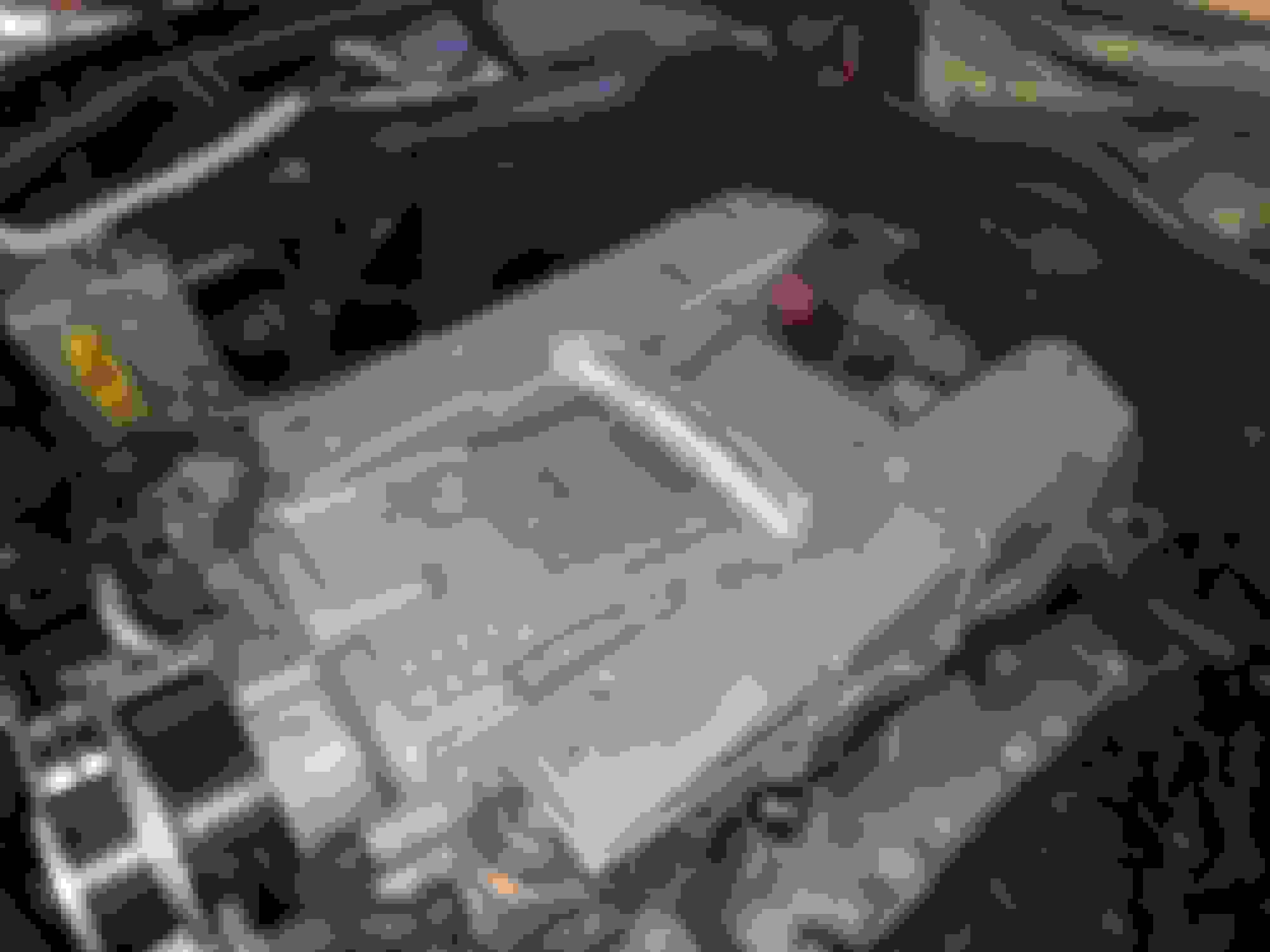
I got them back with the front cross over tacked on before cutting into the manifold for a mockup. (The front has tight clearance but the rear has plenty.) Muck up fit perfect (with the exception of a 1/16" offset he will fix but the coupler could've eaten it up no problem) so I should have them back completed tomorrow.
Extra 0.5" will be shaved off each side for a 1" gap between to be taken up by the coupler.
Well folks, I have some results. Got them back, got them on, and I am seeing 1.5 to 2 PSI drop from previous pressures. I did try to log them but forgot I had turned boost off in torque. Another good sign is that I reset the battery and took had to make a 90 mile round trip. At the end of the trip my LTFTs were at -2% (fuel trims are swapped as far as I know so negative is adding fuel) and prior to the manifold mod my LTFTs were at about +5% (pulling fuel) so just based of the 90 mile trip it appears there it is better flowing.
To recap so far I have:
1.5 to 2 PSI drop
~ 7 % addition of fuel in LTFTs. My hopes are due to the additional air flow haha ( (Granted this is only 90 miles and the LTFTs could still adjust some what)
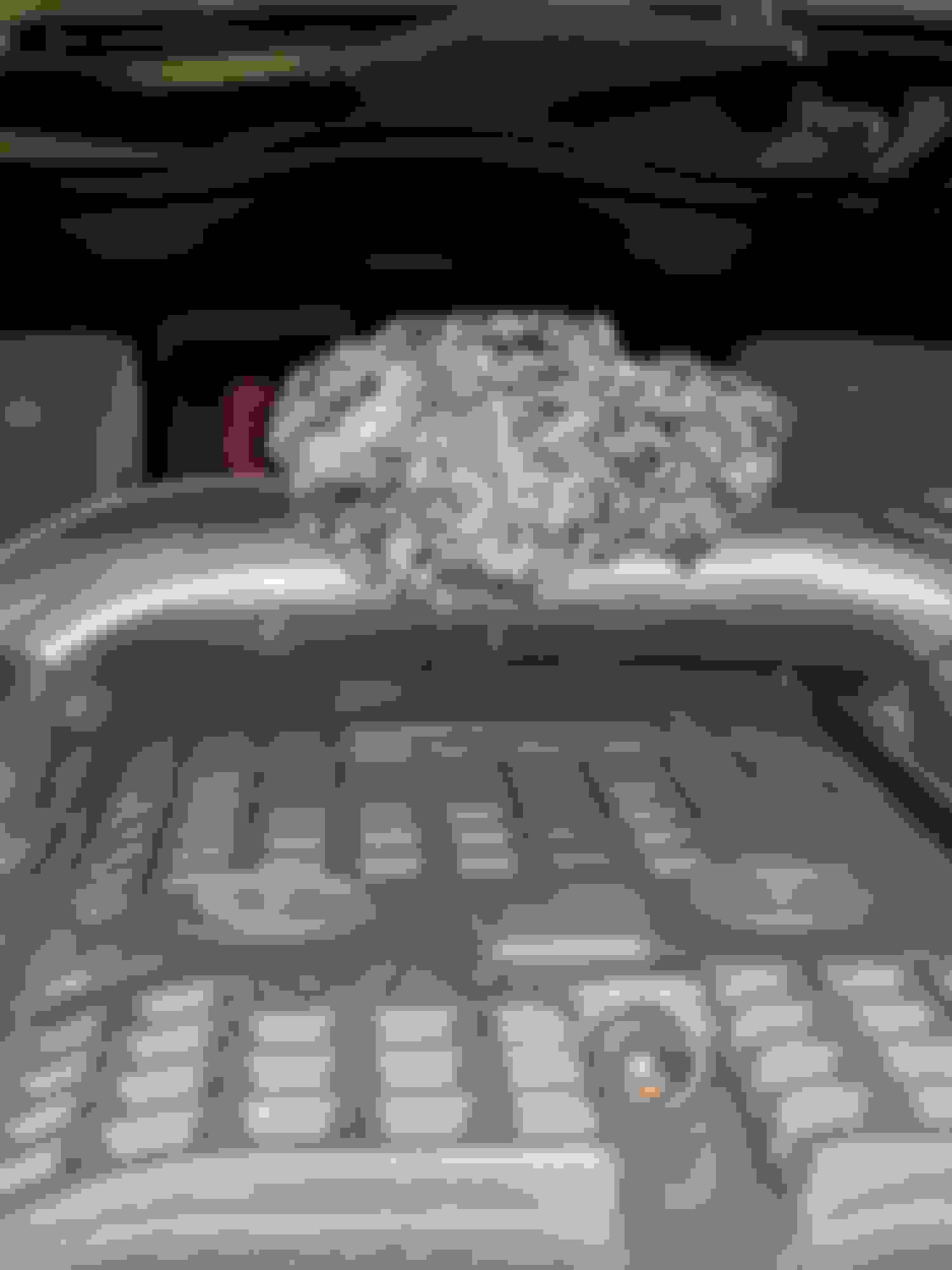
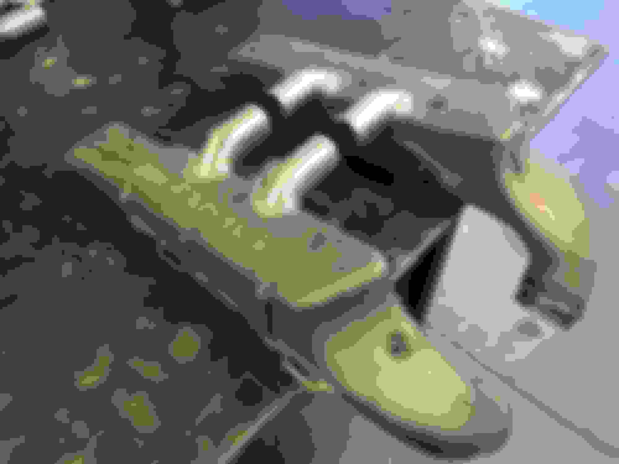
Finished product:
I will clean them up later, maybe powder coat but for now I was rushing to get them on:
Now, tomorrow is track day! No other changes made, similar DA as my last visit. I will get some good logs, and see if I get any 1/4 miles changes!
If the psi drops do iat drop as well? Id think so but i dunnos. That gain seems worthwhile uts almist 20%
Heck yeah it does, if you look at the compressor map no2fast posted, I got from 10PSI to 8PSI, which is 1.68 BAR to 1.54 BAR. A quick google shows SC RPMS at 15,340 with a 77mm SC pulley... which is off the chart. I don't even know if this is the right map for this SC but it's what was posted above. Just assuming 20 m3/min airflow we net:
Approx 5kw(7hp) reduction of SC load on the motor (+7hp)
About a 10C reduction in discharge temp!??! Damn.
I'm hoping there may be gains due to better intake air flow in general also, but that's the info strictly off of the compressor map of the supercharger under different conditions. If this actually is our SC map and 15k ish is the speed for the SC with a 77 or 180 crank the changes will be significantly better, it would be at like 32 m3/min airflow(which is not even on this map)
EDIT: Actually may not be much better at 32 vs 20 airflow, I saw the kW lines get closer but it looks like they go a bit more vertical too, and temp difference appears similar or the same. Might not be much difference whether it's 20 or 32 m3/min airflow.
EDIT again: looks like SC RPM is easy: 151(stock crank)/77 = 1.96 x 6500 (max rpm) = ~ 12,750 max SC RPM. Looking at the numbers again at about the 28 m3/min flow spot comes out to about the same 5kw/10C difference.
Those look awesome. Hoping for positive results under further testing! If your original LTFT's were "Positive", it was adding fuel, so your new "Negative" fuel trims are pulling fuel. You may have cured some minor intake leaks during re-assembly. Are you using TORQUE? I f so, STFT would roughly equate to "ADDITIVE" in MBZ specific which is primarily idle. LTFT would roughly equate to "MULTIPLICATIVE" in MBZ specific which would be everything off idle and beyond.
Those look awesome. Hoping for positive results under further testing! If your original LTFT's were "Positive", it was adding fuel, so your new "Negative" fuel trims are pulling fuel. You may have cured some minor intake leaks during re-assembly. Are you using TORQUE? I f so, STFT would roughly equate to "ADDITIVE" in MBZ specific which is primarily idle. LTFT would roughly equate to "MULTIPLICATIVE" in MBZ specific which would be everything off idle and beyond.
That's what I always assumed about the negative and positive but today I found this thread where shardul and loungn from EC both explain that it is actually swapped on mercedes using a standard US OBDII reader: https://mbworld.org/forums/w211-amg/...ms-please.html
Originally Posted by shardul
If you use a regular american OBDII scanner on a Mercedes negative LTFT mean the ecu is adding fuel vice veresa. So for example you put bigger injector and your LTFT are negative that means the ECU is trying to add fuel and hence you need a tune to scale those injectors correctly. On all stock cars LTFT will be between -2 and + 2 %. Any time LTFT go beyoud -25 to +25 % the CEL will be triggerd with a lean or rich condition code on a particular bank.
Not in my experience but I will try to do some investigating and verification tomorrow at work. If I interpret his explanation correctly, By installing bigger injectors and maintaining the original fuel map (for the original injectors) of say 3ms injector on time, the new, larger injectors would flow a greater volume of of fuel per pulse. The negative LTFT would be in response to the upstream O2 sensors higher voltage due to the richer mixture / extra fuel. Thus the negative LTFT would actually be the ME control units adjustment to take away the excessive fuel provided by the larger injectors.
Not in my experience but I will try to do some investigating and verification tomorrow at work. If I interpret his explanation correctly, By installing bigger injectors and maintaining the original fuel map (for the original injectors) of say 3ms injector on time, the new, larger injectors would flow a greater volume of of fuel per pulse. The negative LTFT would be in response to the upstream O2 sensors higher voltage due to the richer mixture / extra fuel. Thus the negative LTFT would actually be the ME control units adjustment to take away the excessive fuel provided by the larger injectors.
I guess some times 1+1 = 3 if you want to try to look at it that way haha. Lets simplify it a little and take the random example out, here is what I focused on from his statements in a little less imaginative way:
Originally Posted by shardul
If you use a regular american OBDII scanner on a Mercedes negative LTFT mean the ecu is adding fuel vice veresa.
Originally Posted by shardul
your LTFT are negative that means the ECU is trying to add fuel
Originally Posted by shardul
see here is where it gets confusing, negative means the ecu is adding fuel
If you want to ignore all of those statements, and then try to over think the theory behind a quick "for instance" example than sure lol. EDIT: I don't actually know what is right, I just found these posts by shardul and EC tossing an agreement into the thread as well. What is actually correct I don't know, but it's a stretch to take those statements and try to twist them into trying to say positive LTFTs means the ECU is adding fuel. If you have any way to find out for sure that would be awesome Hell, it would be easy to test! This weekend I'll block off one of my filters, reset trims and cruise around ahha. Should be running pig rich and pulling fuel.
Well folks, I have some results. Got them back, got them on, and I am seeing 1.5 to 2 PSI drop from previous pressures. I did try to log them but forgot I had turned boost off in torque. Another good sign is that I reset the battery and took had to make a 90 mile round trip. At the end of the trip my LTFTs were at -2% (fuel trims are swapped as far as I know so negative is adding fuel) and prior to the manifold mod my LTFTs were at about +5% (pulling fuel) so just based of the 90 mile trip it appears there it is better flowing.
To recap so far I have:
1.5 to 2 PSI drop
~ 7 % addition of fuel in LTFTs. My hopes are due to the additional air flow haha ( (Granted this is only 90 miles and the LTFTs could still adjust some what)
Finished product:
I will clean them up later, maybe powder coat but for now I was rushing to get them on:
Now, tomorrow is track day! No other changes made, similar DA as my last visit. I will get some good logs, and see if I get any 1/4 miles changes!
Very nice work! I wouldn`t being focused on the ltf / stf stuff too much. This is mainly for the closed loop not for WOT!. I am pretty sure the ecu needs some time to adapt the fuel maps. There should be much more torque in low / midrange rpm`s from my experience with the SLK32.
You don`t have a AFR / Lambda tool?
Not to detract/derail. But certainly a fair whack less than the 4-5psi that needwings are flogging. Guess the 1-2 might allow for slightly more aggressive pullies for extra gain?


 04-26-2018, 02:19 PM


 ) and torque pro logs with no other changes