Mercedes-Benz C-Class AMG: How to Replace Brake Pads and Rotors
Find out how to replace your brake pads and rotors, along with pricing information and reviews to determine which set is the best for your C-Class AMG.
This article applies to the Mercedes-Benz C-Class AMG (2007-2014).
The contact between the brake pads and rotors creates friction that slows the vehicle down. The larger the brake pad contact area, the more stopping power that is available to the driver. Friction also creates heat which can be damaging to pads and rotors. Rotors can warp, causing a brake pedal pulsation, and brake pads will wear prematurely if the heat is not dissipated, requiring replacement. Learn how to replace the brake pads and rotors on your Mercedes-Benz C-Class AMG with this guide.

Materials Needed
- Floor jack and jack stands
- 1/2" breaker bar (not needed if you have access to air or electric impact wrench)
- 17mm deep well socket
- Ratchet 3/8" or 1/2"
- 8mm and 14mm sockets
- Round chisel 8" in length (or small hex screwdriver)
- Hammer
- Pliers (needle nose and standard type)
- Caliper hanger (metal coat hanger or wire)
- Fluid pump/suction device (depending on the brake fluid level)
- Brake caliper piston compressing tool (C-clamp)
- WD-40 (lubricant)
- Gloves and safety glasses
- Turkey baster or syringe
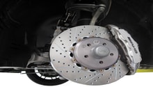
You have some choices when buying new pads and rotors. Typically, brake rotors cost between $200-800 each, whereas brake pads cost $50-100 each. One-piece rotors are cheapest but are also heaviest. They are found on the p30 c63. There is also a two-piece rotor found on the p31 version. These are three to four times the price, but offer better braking performance. Some aftermarket companies make two-piece rotors as well. The price is typically in the middle, and they are the lighter assembly of the bunch.
Choosing the correct pads comes down to several factors, including lifespan, performance, noise, and cosmetics. OEM (original equipment manufacturer) pads have been known to provide a balance, although they do create large amounts of brake dust. Use the links at the bottom of the article to determine which pads and rotors are best for you.
Warning
It is advised to always wear gloves and safety glasses. Brake fluid is corrosive, and will damage both you and any painted surfaces on your Mercedes-Benz.
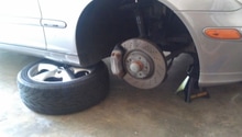
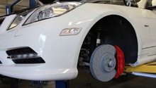
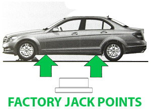
Step 1 – Raise and support the vehicle
Only one wheel needs to be lifted off the ground at a time.
(Related Article: How to Jack Up Your C-Class - MBWorld.org)
Pro Tip
Break your lugnuts loose before lifting the vehicle in the air. This will make removing the wheel much easier.
Step 2 – Remove the brake caliper(s)
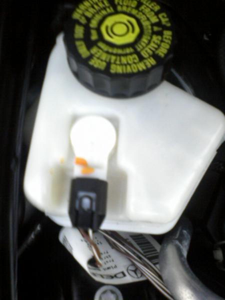
To begin, check the brake fluid level by twisting the cap on the brake fluid master cylinder off. If it is near or above the full mark, some fluid will need to be suctioned out. Later on as you compress the brake caliper piston(s) in the fluid level will rise. How high depends on how worn your brake pads are and how many you are changing.
Move to the right rear brake caliper and unbolt the brake wear sensor from the caliper. The bolt is 8mm. These are typically only found on the passenger side, but there is a variance between models and years.

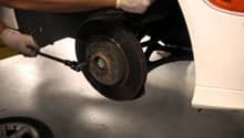
Now remove the caliper guide pins. Using a punch or an appropriate screwdriver, carefully knock the pin towards the vehicle. Once it is sticking out about half way, use your pliers and, with a twisting motion, pull the pin out from the caliper. A small amount of WD-40 can be used, but only apply it to the pin.
Note
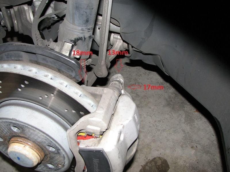
The front calipers also have a 14mm bolt that will need to be removed.
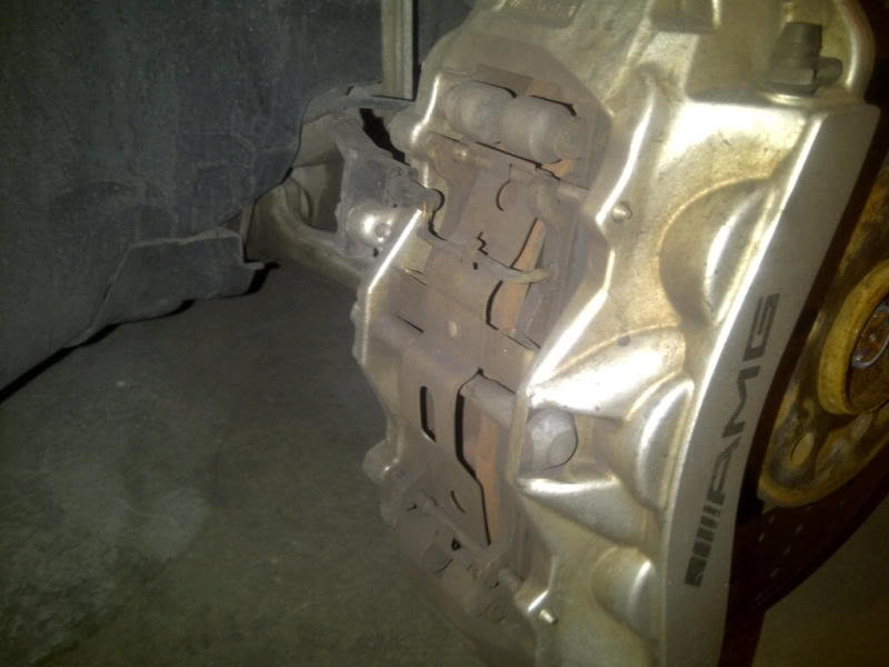
Figure 4. Front caliper bolt. 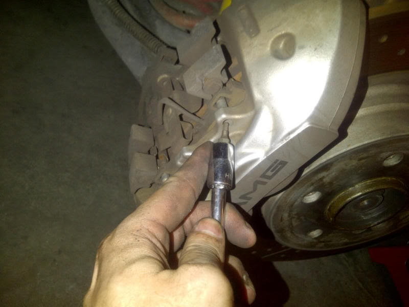
Figure 5. A small hex screwdriver bit is being used to remove the guide pin. 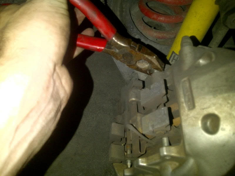
Figure 6. Using pliers to pull the pin out from the caliper.
Remove the two bolts fastening the brake caliper to the wheel carrier. There may be a protective rubber boot around that pops off. Use a wire or caliper hanger to prevent the brake hose from being damaged.
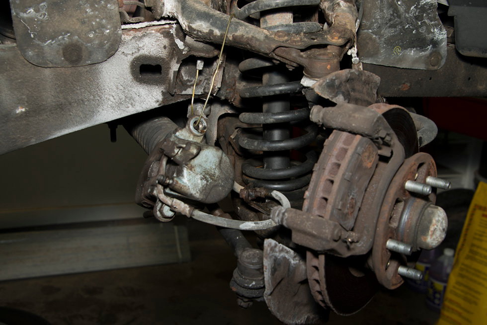
Note
If you are only removing the pads, then you don't need to hang the caliper. The pads can be accessed and replaced at this point.
Step 3 – Remove the brake pads
Remove the brakes pads by sliding them out of the rotor. On the models fitted with a brake wear sensor, remove it by gently squeezing and pulling up on the small metal clip holding the sensor onto the pad.
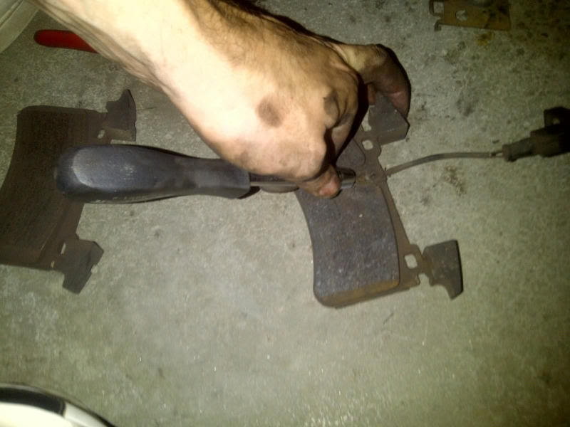
Figure 9. This brake wear sensor is being improperly removed with a screwdriver. 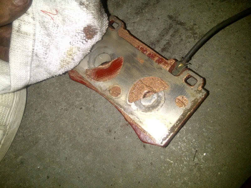
Figure 10. The brake pad wear sensor is clipped into the side of the brake pad.
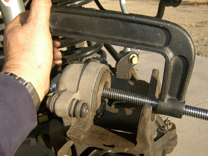
Step 4 – Compress the brake caliper piston
Using the caliper piston compressor, retract the piston(s) back into the caliper. Do not retract the piston all the way into the caliper. Leave about a 1/4" of the caliper exposed, otherwise the caliper boot can be damaged.
Pro Tip
Remember to keep an eye on the brake master cylinder fluid level.
Step 5 – Remove the rotor(s)
Removing the rotors is easy. All that is required is removal of the set screw/retaining bolt. Then, they simply slide off the wheel studs.
Step 6 – Re-install the rotors, brake pads and calipers
Installation is the reverse of removal.
- Fit the rotor to the hub, and fasten the retainer bolt to steady it.
- Pop the new brake pads into the calipers.
- "Massage" the caliper's pistons to get them back into place.
- Fasten the caliper hub with the large 14mm bolts.
- Connect the caliper slide pins in place, and give the calipers a good shake to make sure that the pads are fitted properly and not loose.
- Fit the wheel to the hub and torque the wheel bolts to 90 ft-lbs.
- Remember to top off your brake fluid level, if necessary.
Related Discussions
- How to Replace Brake Pads - MBWorld.org
- Removing/Replacing Brake Calipers - MBWorld.org
- Cost of Replacement Brakes - MBWorld.org
- Replacing Brake Pads - MBWorld.org
- How Often to Replace Brakes - MBWorld.org