When you click on links to various merchants on this site and make a purchase, this can result in this site earning a commission. Affiliate programs and affiliations include, but are not limited to, the eBay Partner Network.
Well...I installed the surface mounted LEDs...and they all bench tested on when I tried them before assembling the UCP...now installed - THEY WONT LIGHT!
First)
Is the UCP smart enough to know not to send voltage to these LED locations - even though the PCB has solder spots for LEDs? - I need to pull apart a UCP again to trace the power leads...DANG IT!
Second)
I am reading that the UCP may need to be "coded" (if at all possible) to run the LEDs and possibly even read (if there are) CAN signals from never loaded button locations...Can I start simply by "Coding the UCP to turn on these LEDs?" That seems awfully complicated to just illuminate these icons I have made...
Third)
For those of you that have UPGRADED with OEM stuff...IE - added a switchrow with and for heated seats, rear sunshade, IMS, etc...did you NEED TO CODE the NEW UCP to "work" the OEM options and also "illuminate"...I would think not...In this picture - I DO NOT HAVE IMS OR OEM PTS INSTALLED...yet this "optioned UCP" did have the "buttons" to operate IMS and PTS...and these OEM LEDs ARE infact illuminating! AARRGGG!
Thanks!
Jake
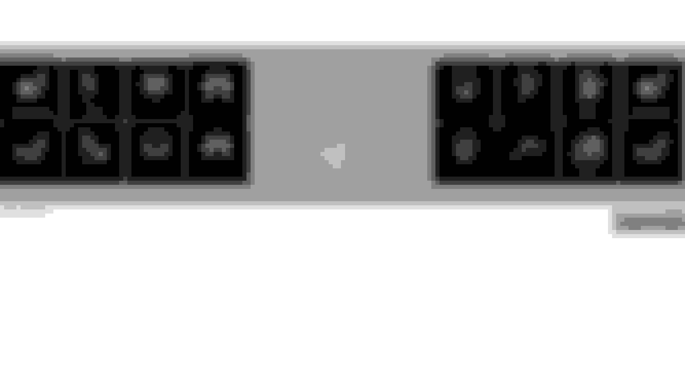
Jake, what did you use for the current limiting resistors? Soldering the LEDs alone will not work, because as you found the circuit is not complete. I retrofitted LEDs on to the headlight switch circuit board because 07s (and maybe the 06s) do not have the LEDs that show the switch position. See my pics of the what I did there and you probably have a similar situation. The LEDs with the black outline are the ones I added.
Oh yeah, the ohm value of the resistor is dependant on the LED that you are using so that you can match the brightness to the other existing LEDs. If you want I can dig up my leftover resistors for you to benchmark.
Thanks for some insight! I have seen some images of the "full illuminated" light switch...never knew anyone was adding in LEDs...I have thought of this Mod too...Why didn't M-B just add these LEDs???
I want them as bright as OEM - I am using OEM "donor" LEDs from another UCP...I just want them to light - do I just need a bridge?
Please let me know what resistors you used so I can benchmark them...I have pulled out my "Custom" UCP - and will open in up as soon as I get a minute...I swapped it out for another "Custom" UCP with only my custom icons...no "added" non-OEM features...
Thanks,
Jake
If you are using donor LEDs than they most likely match the ones I found since I matched the part number (minus the black surround, that's the only difference) I found that a 3.3K Ohm resistor gave the proper brightness. However since the LEDs in the UCP are a little closer to the button than in the headlight switch you may need to go a little darker, 4.7K ohm did dim it to some degree so you may try that also. In my pics you will notice that the resistors are soldered on the back side of the PCB, this was because I had a really hard time finding surface mount resistors like the OEM used. The 1/8th watt look a little funny, but do the trick.
Oh yeah, don't bridge the connection, 12V without current limiting will most likely destroy your LEDs and then you will be hunting for more.
Thanks jr_smith68! Some real help on this thread of mine! Here is the image I found of a fully illuminated light switch...it sure does look nice!
I will print out your information and get to work...Where did you get OEM part number LEDs??? That sure would help me finish some other work!
Thanks,
Jake
(Here is an image of the OEM UCP front [mirrored to line up with the back above] right side...where do you suggest I place the ~4k Ohm resistors?
Jake,
Studying your picture I overlaid the position you want to place the resistors. At least for the two positions in the pic that didn't have LEDs. The illumination LEDs look a lot smaller than the LEDs I used for the headlight switch. I got mine off of Ebay, pretty cheap. When I get home, (travelling right now) I will find the tag off the package and let you know what seller I found.
Also, where did you get that pic of the headlight switch? Is that yours? Nice exposure!
I've been wanting to add lights to my 2005 non-illuminated icons for my headlight position switch. Like you said, 2007, 2006 (and also 2005's) don't have these icons lit up. Seems as though sometime in 2005, MB, in their cost-cutting, decided to eliminate these LED's. I had heard that it couldn't be done and that I'd have to get a 2004 or earlier headlight/mirror/headlight washer switch module, and swap mine out. Of course, this would have cost into the hundreds.
My question is this...how difficult would it be to add LED's resistors, etc to my existing circuit board? Any step-by-steps available from you doing this to your Geary? How difficult would this be for someone that has very limited (ok, practically none) knowledge in circuit/resister/LED/Ohm stuff? I'm pretty good when it comes to viewing pics and how to's.
Great efforts on your switches Jake !! I've been this thread since practically day 1.
Studying your picture I overlaid the position you want to place the resistors. At least for the two positions in the pic that didn't have LEDs. The illumination LEDs look a lot smaller than the LEDs I used for the headlight switch. I got mine off of Ebay, pretty cheap. When I get home, (travelling right now) I will find the tag off the package and let you know what seller I found.
Also, where did you get that pic of the headlight switch? Is that yours? Nice exposure!
Geary
Geary,
I used OEM LEDs from a donor UCP...I used a small side edge (tweezers) type soldering iron. These TWO (and all opened PCB Boards in this thread) are the FULL USA DM UCP...part A230-280-15-10 without my added LEDs...I need to open that up again! ARG! Here is the LEFT side (with ESP OFF) - any help would be GREAT!
The headlight switch is from my reference items...it is NOT my image, I did not take it...it was a "future project inspiration shot"
Cintoman - You could do it - It looks like all you will have to do is copy Geary's image! ... If you are not comfortable with a soldering iron, just find one that is! I hope to get this "CUSTOM UCP" up and running "someday!"
Geary,
I used OEM LEDs from a donor UCP...I used a small side edge (tweezers) type soldering iron. These TWO (and all opened PCB Boards in this thread) are the FULL USA DM UCP...part A230-280-15-10 without my added LEDs...I need to open that up again! ARG! Here is the LEFT side (with ESP OFF) - any help would be GREAT!
Jake,
I dug up my old UCP that I replaced when I added the IMS and PTS, so I can verify the resistor locations for all illum LEDs and the polarity of the LEDs. That is also critical and could be an issue for you. I should have something for you tomorrow. I have attached the spec for the mini TOPLED from OSRAM. One problem is that I can't find any sellers of the mini TOPLED on eBay. For the headlight switch project I used all standard TOPLED which matched the OEM LEDs.
Looks like there is some interest in retrofitting the headlight switch. When I did mine a year ago it didn't seem as if too many people were looking to do that. I'll put together a how-to from the pics I took and post that in a new thread. As Jake said, if you are handy with a soldering iron you can do it. I used my 25W iron from Radio Shack and ground down the tip to a sharp point.
I dug up my old UCP that I replaced when I added the IMS and PTS, so I can verify the resistor locations for all illum LEDs and the polarity of the LEDs. That is also critical and could be an issue for you.
Geary
Hi Geary,
I (should) have the polarity correct, I checked the LEDs under a large magnify glass before install to note the OEM set up (and the "dark spot") to which to place the LEDs...Should be right - as they did light up with the bench test.
Anyhelp - and your current help is GREATLY appreciated!
Thanks,
Jake
Ok got it all figured out. Since you are using the donor LEDs picking the resistor is easy. You want to use a 4.7K ohm. You can get 1/8 watt versions from Radio Shack, part number 271-008. However, you may be able to unsolder some from your donor UCP like you did the LEDs. Look for the black resistors marked "4701." Sounds like you have the polarity figured out as you probably matched the orientation of the existing LEDs. The little dark spot goes toward the outside edge (top opposite bottom). As far as where to place the resistors, I have that illustrated in the attached PDF. Good luck! Show us a nice pic with it all lit up!
Thanks Geary!,
That is amazing help - and you didn't have to make a PDF...But I thank you for doing it! I will now tear open the UPC and see what I can do!
Thanks,
Jake
Love this thread over here as well..And as you saw in the "other" thread I found my UCP with the wiper buttons finally after hours of research and they where closer than you could think..
Hello Jake....Where did you get that Climatronic from in the picture? I want to know if you have a part number I can reference. I want one of those, but have been unable to find one. Thanks and sorry for hi-jacking your cool thread.
Originally Posted by BF_JC230
Well...I installed COMAND last weekend - Was able to hang out with my Dad...change the oil, plugs all filters and install the new HU...While I was there I figured it was time to install one of my "Custom" UCPs...Here it is!
Hello Jake....Where did you get that Climatronic from in the picture? I want to know if you have a part number I can reference. I want one of those, but have been unable to find one. Thanks and sorry for hi-jacking your cool thread.
I put a lot of information in this w203 forum and in the ///AMG w203 forum...My research indicates that these are BUILD DATE SPECIFIC and you need to match some prerequisites to obtaining a functioning digital HVAC controller. WIS will be a huge help.
My main objective, aside from aesthetics and ergonomics was the [REST] feature for winter.
Hi Jake. Emailed you in another thread before I saw this one.
I think the work you've done is fantastic.
My goal was also to get the non working buttons to do something, but I gave up when I realized what was involved and settled on just adding factory icons to where they normally go even though my car doesn't have the features.
However the work you have gone thru just aesthetically is beautiful.
I might suggest, since you have the molds, that the three types of buttons that you have made, white buttons painted black with no icons, should be saleable in volume. You might even take orders saying that you will make them if you get for instance 100 takers at X price.
You can provide laser etching settings and we can do the actual icon etching locally.
Then people can put in their own icons. You deserve to recoup the time and trouble you put into this, and it seems like you will be needing to purchase some donor circuit boards to continue your work. Also since you have made your own icons, I would be interested in purchasing from you the ORIGINAL FACTORY ICON BUTTONS for parktronic, sunshade towing and the icon below the towing button.
We are all looking forward to your decoding of the canbus for the unused buttons or in the alternative, a how-to for microswitch installation that can be used.
Another alternative is, can multiple switches be programmed for instance as sunshades? Since the sunshade ends up being a simple output, If each button operated a different "sunshade" You would end up with usable outputs by duplicating current canbus programming rather than having to create your own program. Its an expensive way to do it but it might be less work.
Also once you figure it out you are going to have a lot of people clamouring for step by step instructions...people with a whole lot less skills than you have, so simpler may be more duplicable.
Anyway, my other email is still valid, and I look forward to watching your electronic progress.
Here is some stuff I dug up. See the attached file. Don't know if it helps.
Good luck.
Dan
P.S. The picture in the previous post will not enlarge or show up on a separate web page if opened in a new tab.
Last edited by dspevack; 06-07-2012 at 10:58 PM.
Reason: More info
We should come up with a thread listing any buttons we'd like to have on our upper switch row. Jake could engrave these for us in his spare time Just for fun of course.
Imagine the look on people's faces when they sit in the driver's or pass seat and saw these buttons. Here are some of mine off the top of my head. I'm at work now so I can't MS Paint these up:
- eject button icon with a seat icon above it
- rear 1/2 side view of car with oil/gravel coming out the back
- side view of car raised up 3 feet higher (to match the height of SUV's)
- rocket/missle icon
- boat icon (for those underwater excursions)
- "hybrid mode" icon (to "explain" how we C230K owners get >35mpg with our cars...uh, on second thought, NO..no need to pretend we're a hybrid)
- B2 bomber icon (for stealth mode)
- turbo boost button (OK, so I watch the 80's Knight Rider)
- binoculars icon
- pistol icon
- police car icon (for when we need to go into police mode to make citizens' arrests)
I'm sure we could come up with a ton more of these. Any other ideas? Jake...you feel like making some of these non-functioning buttons for us?
All joking aside, Jake, you are doing an incredible job on this. Your dedication and meticulousness are worthy of Mercedes-Benz hiring you as an engineer.
Cintoman
Amen! This is an amazing thread. I thought I was fussy, but I've been sent to the back of the fuss bus.
Can we add "smoke bomb" or "drop shards of metal" in case you're being chased by zombies (likelihood of which appears to be going up)?
Jake,
I almost forgot.
ON my 2008 clk350 convertible I decided to upgrade the heated driver's seat to one with lumbar support also. The one I purchased was out of a wreck and it just so happened that the seat not only had heat and lumbar support, but also the built in fan system too. As part of the deal with the junkyard that sold it to me, I had them include the UCP which had the factory seat fan buttons, and the plugs that went into it. This way I might know the difference between what wiring my car had and what it needed.
It turns out there is an extra blue and green wire that are added to the wiring with the fan system and plug into the back of the unit. I don't know if that is one color for each button (drivers side and passenger side) or both wires are necessary and carry canbus information, but those wires can specifically defined as in use for the fan features on the seat.
Thanks Saprissa - I have never been able to find an image showing anything there, or read of any facotry options - BUT the PCB is prewired for it - the soft key rubber buttons are there underneath the hard plastic button...If I could remove this (these) sections of the PCB I would have a TON more room to mount my switches...
Anyone?
Jake
Hello all from russian drunk people, lol. Tell me please, how its cuprum contacts on plate is works ? This is cuprum pins on rubber, or what ?
Anyone ever have any luck making/etching their own icons?
I'm thinking of redoing mine, again, to just “On/Off” as I’m still not comfortable hacking into the CANBUS...and...I’ve never fully invested in some of these ideas based on that...


 10-10-2009, 09:31 AM


 this thread since practically day 1.


 Just for fun of course.