


DIY: Pre-Facelift with Bose System to 2005+ Console Swap with Comand (56k will melt)

Thread Starter
Super Member
Joined: Oct 2007
Posts: 569
Likes: 0
From: Bay Area, CA
Volvo
DIY: Pre-Facelift with Bose System to 2005+ Console Swap with Comand (56k will melt)
Hey guys, For those who didn’t know, I attempted and succeeded a console swap to the newer face lifted w203’s. I had a budget in mind and kept to it. I also had the BOSE system without the navi which I think is the worse of the worse to swap. (By having a Comand, You have a lot easier time wiring certain things) This is a basic guide and information for those who wish to attempt this swap. I would suggest this only to people who don’t want an aftermarket head unit and want the to retain the factory look as much as possible but give your sound system am extra umphf  . I based my research on a few other projects people have attempted but not exactly like mine due to I have the BOSE system and how to figure out a lot of grey areas. I also did a lot of trial and error and research on my own. The + side to this conversion is you have an aftermarket Amp that works with pretty much all speakers on the market, plus I can add a sub very easily by getting another amp, mounting it, and running power..
I take no responsibility over anything you do to your car or anything that this guide shows you. This is a basic guide to help anyone that wants to attempt this. I have included a bunch of my own pictures and videos to help you along the way
Difficultly: Well I hold a bachelors degree in computer engineering (I’m not an English major so please bare with me on the grammar) so wiring is very easy for me… If your confident in soldering, wire striping, disassembling your console, and generally handy then this should a walk in the park
Basic Tools:
Flat Head Screwdrivers
Philps Screw Drivers
Torx Drivers 20 through 45 may be needed
Wire Cutters
Scissors
Electric Tape
Painters Tape
Soldering Gun with Solder
Heat Wrap
Lighter
Female disconnects (Look it up on Google if your unsure what this is)
Flanged spade connectors
Black Marker
Multimeter volt/ohm
Materials Needed:
- Comand Unit – I got mine out of a wreck c55 for $400.00 (can find them on ebay too) (I used the MCSII USA)
- Buttons & Button Faceplate – Ebay – $50.00
- Basic AC Controller & Faceplate – Ebay – $120.00
- GPS Antenna - http://mbdoctor.com/ - $79.00
- Wiring Loom - http://mbdoctor.com/ - $50.00
- 2005+ Plastic Cluster Frame - http://www.mbscashopen.se – $60.00
- Speaker Wire – 40ft – $40.00
- Cat 5e Cable – 3ft – $3.00
- Aftermarket AMP (If you want to use your stock speakers make sure you get one that does 2ohm as all Bose speakers are at 2ohm) This is what I got - POLK AUDIO ---
PA200.4 CHANNEL 320w – $120.00
- Hi-Low Converter PERIPHERAL SVEN4 LINE OUTPUT CONVERTER 4CH – $20.00
- Shielded Twisted RCA Cables – 15ft – You need 4 Cables total they usually come in packs of 2. $45.00
- 8 gauge wires – You need 2 3ft Black and red wires – $12.00
- Mercedes AUX Cable (If you want an Aux cable to plug into an ipod) - $60.00
- Set aside another 50-100$ just in case for little things.
Total that I Spent: $1108.00
As I’m making a basic guide, I will not include how to take something apart. What I did is search the forums for different things, such as removing the Glove box, removing the Radio….and ext….. This project can take a couple days if not more. It took me over 2 weeks to finish everything, but that’s because of work, Girlfriend, family stuff, and I did all the labor myself.
Step 1: (Disconnect Battery)
Remove Center Trim & Air Vents


Remove Radio, Buttons and Ac

Remove Glove Box, 6 Disk Changer, Blower Shielding trim, and side trim on the radio frame.


Remove Radio/button Frame (Black) there’s a bunch of screws. Once unhooked it will slide toward where the glove box was.


Step 2:
Place the new Frame where you took the old one out… This does take time; I cut off and trimmed some plastic pieces off the frame to get it to slide in.
Once done, Screw the frame into the Interior pieces….. Do not start piecing the glove box together, we still need it undone. Gather These Pieces…

Read the first Post I made on this thread, Now is the time to test your unit
https://mbworld.org/forums/c32-amg-c...nsole-c32.html
Ok here’s a slight overview of the Stock harness system with BOSE system.
For the non Navi (Which I had) There are 2 cable Connectors for the radio, One is power, the other is the Canbus Connector. The Wireloom you purchased for the newer navi has a connector like this:

The One with the 3 Plug Male on the Wireloom is the power to the navi. Hook up the Power from the stock harness (Looks like this)

Now you need to hook up the other end to the comand.

We now need to hook up the radio antenna adapter.

Once Those things are hooked up, You should be able to power up your comand unit (after connecting your battery back up)
VIDEO: http://www.youtube.com/watch?v=P5UJveo24mI

Continued on Post 2
. I based my research on a few other projects people have attempted but not exactly like mine due to I have the BOSE system and how to figure out a lot of grey areas. I also did a lot of trial and error and research on my own. The + side to this conversion is you have an aftermarket Amp that works with pretty much all speakers on the market, plus I can add a sub very easily by getting another amp, mounting it, and running power..I take no responsibility over anything you do to your car or anything that this guide shows you. This is a basic guide to help anyone that wants to attempt this. I have included a bunch of my own pictures and videos to help you along the way
Difficultly: Well I hold a bachelors degree in computer engineering (I’m not an English major so please bare with me on the grammar) so wiring is very easy for me… If your confident in soldering, wire striping, disassembling your console, and generally handy then this should a walk in the park
Basic Tools:
Flat Head Screwdrivers
Philps Screw Drivers
Torx Drivers 20 through 45 may be needed
Wire Cutters
Scissors
Electric Tape
Painters Tape
Soldering Gun with Solder
Heat Wrap
Lighter
Female disconnects (Look it up on Google if your unsure what this is)
Flanged spade connectors
Black Marker
Multimeter volt/ohm
Materials Needed:
- Comand Unit – I got mine out of a wreck c55 for $400.00 (can find them on ebay too) (I used the MCSII USA)
- Buttons & Button Faceplate – Ebay – $50.00
- Basic AC Controller & Faceplate – Ebay – $120.00
- GPS Antenna - http://mbdoctor.com/ - $79.00
- Wiring Loom - http://mbdoctor.com/ - $50.00
- 2005+ Plastic Cluster Frame - http://www.mbscashopen.se – $60.00
- Speaker Wire – 40ft – $40.00
- Cat 5e Cable – 3ft – $3.00
- Aftermarket AMP (If you want to use your stock speakers make sure you get one that does 2ohm as all Bose speakers are at 2ohm) This is what I got - POLK AUDIO ---
PA200.4 CHANNEL 320w – $120.00
- Hi-Low Converter PERIPHERAL SVEN4 LINE OUTPUT CONVERTER 4CH – $20.00
- Shielded Twisted RCA Cables – 15ft – You need 4 Cables total they usually come in packs of 2. $45.00
- 8 gauge wires – You need 2 3ft Black and red wires – $12.00
- Mercedes AUX Cable (If you want an Aux cable to plug into an ipod) - $60.00
- Set aside another 50-100$ just in case for little things.
Total that I Spent: $1108.00
As I’m making a basic guide, I will not include how to take something apart. What I did is search the forums for different things, such as removing the Glove box, removing the Radio….and ext….. This project can take a couple days if not more. It took me over 2 weeks to finish everything, but that’s because of work, Girlfriend, family stuff, and I did all the labor myself.
Step 1: (Disconnect Battery)
Remove Center Trim & Air Vents
Remove Radio, Buttons and Ac
Remove Glove Box, 6 Disk Changer, Blower Shielding trim, and side trim on the radio frame.
Remove Radio/button Frame (Black) there’s a bunch of screws. Once unhooked it will slide toward where the glove box was.
Step 2:
Place the new Frame where you took the old one out… This does take time; I cut off and trimmed some plastic pieces off the frame to get it to slide in.
Once done, Screw the frame into the Interior pieces….. Do not start piecing the glove box together, we still need it undone. Gather These Pieces…
Read the first Post I made on this thread, Now is the time to test your unit
https://mbworld.org/forums/c32-amg-c...nsole-c32.html
Ok here’s a slight overview of the Stock harness system with BOSE system.
For the non Navi (Which I had) There are 2 cable Connectors for the radio, One is power, the other is the Canbus Connector. The Wireloom you purchased for the newer navi has a connector like this:
The One with the 3 Plug Male on the Wireloom is the power to the navi. Hook up the Power from the stock harness (Looks like this)
Now you need to hook up the other end to the comand.
We now need to hook up the radio antenna adapter.
Once Those things are hooked up, You should be able to power up your comand unit (after connecting your battery back up)
VIDEO: http://www.youtube.com/watch?v=P5UJveo24mI
Continued on Post 2
Last edited by OverDrive; Feb 10, 2010 at 02:24 AM.
Thread Starter
Super Member
Joined: Oct 2007
Posts: 569
Likes: 0
From: Bay Area, CA
Volvo
Step 3:
Now if it doesn’t boot, Recheck your connections or you made need to have the Comand programmed….When I did it I never had to have it programmed. Once you verified it boots up and turns on, disconnect your battery and unplug the Comand from the wiring loom. (Leave the Stock Power Connector connected to the wire loom). Now Its time to do a bit of wiring. Looking at this picture below
The Top connector should have nothing connected to it, while the bottom one is plugged into the factory harness. This top connector is the output to the speakers. This is where your speaker wires will come in handy. Cut 4 6ft pieces of speaker wire. Each speaker wire should have a positive and negative attach to one another… So (8 wires total). Now disconnect the stock harness from the wire loom. Find the correct “Female disconnect” that fits on to each tab on the speaker connector on the wire loom. After Script both ends of the speaker wires (positives and negatives) (Make sure you know which is which for later on) and Crimp the female disconnect to both Negative and positive on the speaker wire. Once you do all 8 wires, I would suggest wrapping them (If there not pre-wrapped) with electrical tape so when they snap in next to each other if they happen to bump it won’t short. After the wrapping, Snap them into the Speaker connector on the wire loom.


In my pictures above, I took out an old harness I cut out of the c55 so my wires would match the wire loom so I would know what speaker channels are right, left, front and rear. On the Wire loom you should see that there are a couple different color wires on the speaker connector. Here is the Color Code.
- 2 wires that are solid orange (positive) and orange with a brown stripe (negative) = Front Right
- 2 Wires that are solid white (positive) and White with a brown stripe (negative) = Rear Right
- 2 Wires that are solid Olive Green (positive) and Olive green with a brown stripe (negative) = Front Left
- 2 Wires that are solid pink (positive) and solid pink with a brown stripe (negative) = Rear Left
I would suggest you use your painters tape and a marker and label each speaker wire to the indicated channels. Once completed, We now need to run those wires underneath and across where the glove box use to be, down to under the floor.


You should have a foot or more of extra cable at the floorboard in front of the passenger’s seat. (If you have more that’s great, You can adjust and snip off the extra during the next step.

Step 4:
You now need the Hi-Low Converter that converts the output from the Comand Unit to the Wire loom through the speaker wires you connect to the wire loom into RCA Output. Aftermarket Amps usually use an RCA input so this step is a must. If you purchase the one like mine, it comes with harness. Please Read the instructions that come with. This will tell you what wires are Front Right, Rear Right, Front Left and Rear Left. Once you identify those, you now must connect the speaker wires to the harness and solder each wire. You will need your heat wrap as well here. The end result should look like this.


Don’t mind that I have the Glove box back together (I took the pic at a later date)

Once your done soldering (Note: Make sure you didn’t solder the grounds that come with the hi-low converter, There are 2) Place it here (If you have my model) and connect the ground (The one with the harness you just solder in) to the ground located right next to the mounting location.


You may have to cut away some foam on the Carpet floorboard to get everything to fit. Once that’s completed, Take your Shielded/Twisted RCA cables Hook them up to the Hi-Low Converter. (Again keep track what’s Left, Right, Front and Back). The W203 has a Wire tunnel which you can use to run your RCA cables all the way back to the trunk area. You do need to take some interior trim pieces off and the passenger rear seat that you will also need to take out to run the RCA’s. (This would be a prime time if you are running a more powerful amp (Then what I have) to run a Power Cable from the battery (With a fuse of course) to the trunk) After the RCA cables and or power cables are at the Spare Tire wheel hub, Put Your backseats and your trim back together (expect the Glove box assembly.
Step 5:
Back to the wire loom. If you purchased the aux Cable, now would be a good time to run it behind the glove box. Make sure the Female end (The 3.5 Jack to plug in your ipod) is toward the glove box, and the connector end is where or next to the wire loom. Once done, Re assemble your glove box and the pieces that you needed to take off to get the new radio frame in. On the Wire loom that connects to your factory harness, all connectors should now be filled by either the speaker wires we rigged up and the power connector from the stock harness.

Find the cable that looks like the picture below that’s attached to your wire loom

This is your CanBus Cable Hi and Low output. We now need to connect this to your car’s canbus system as these interfaces with the front Sam. Find this cable off your stock harness

It should be the other cable we didn’t hook up to the Wire loom. Find the 2 wires that are Brown and Brown with a red stripe that are equal to the thickness of the wire loom Canbus Wires. Once located you need to tap into those wires by striping them partly so that the bare copper wires are shown on both cables. Then you need to cut off the connector and strip the wires on the Wire loom as well. Then Match up the wire colors from the wire loom to the stock canbus harness (So Solid brown hooks up to solid brown, and the Brown with the red stripe hooks up to the one on the Stock harness).
Step 6:
Now we need to make the custom harness for the new button cluster for the console….I will not be able to walk you through this as it’s pretty hard to describe. Look at pictures, to see what I did. I will update this later.
Please note: On Pre-face lifted cars the Connector is a Square. On the Face lifted W203’s the connector is now a rectangle. For the Heated seats however this connector is unchanged and plugs into both button clusters. If you don’t have the buttons hooked up or they are incorrectly hooked up, your SRS light will come on.


Continued on Post 3
Now if it doesn’t boot, Recheck your connections or you made need to have the Comand programmed….When I did it I never had to have it programmed. Once you verified it boots up and turns on, disconnect your battery and unplug the Comand from the wiring loom. (Leave the Stock Power Connector connected to the wire loom). Now Its time to do a bit of wiring. Looking at this picture below
The Top connector should have nothing connected to it, while the bottom one is plugged into the factory harness. This top connector is the output to the speakers. This is where your speaker wires will come in handy. Cut 4 6ft pieces of speaker wire. Each speaker wire should have a positive and negative attach to one another… So (8 wires total). Now disconnect the stock harness from the wire loom. Find the correct “Female disconnect” that fits on to each tab on the speaker connector on the wire loom. After Script both ends of the speaker wires (positives and negatives) (Make sure you know which is which for later on) and Crimp the female disconnect to both Negative and positive on the speaker wire. Once you do all 8 wires, I would suggest wrapping them (If there not pre-wrapped) with electrical tape so when they snap in next to each other if they happen to bump it won’t short. After the wrapping, Snap them into the Speaker connector on the wire loom.
In my pictures above, I took out an old harness I cut out of the c55 so my wires would match the wire loom so I would know what speaker channels are right, left, front and rear. On the Wire loom you should see that there are a couple different color wires on the speaker connector. Here is the Color Code.
- 2 wires that are solid orange (positive) and orange with a brown stripe (negative) = Front Right
- 2 Wires that are solid white (positive) and White with a brown stripe (negative) = Rear Right
- 2 Wires that are solid Olive Green (positive) and Olive green with a brown stripe (negative) = Front Left
- 2 Wires that are solid pink (positive) and solid pink with a brown stripe (negative) = Rear Left
I would suggest you use your painters tape and a marker and label each speaker wire to the indicated channels. Once completed, We now need to run those wires underneath and across where the glove box use to be, down to under the floor.
You should have a foot or more of extra cable at the floorboard in front of the passenger’s seat. (If you have more that’s great, You can adjust and snip off the extra during the next step.
Step 4:
You now need the Hi-Low Converter that converts the output from the Comand Unit to the Wire loom through the speaker wires you connect to the wire loom into RCA Output. Aftermarket Amps usually use an RCA input so this step is a must. If you purchase the one like mine, it comes with harness. Please Read the instructions that come with. This will tell you what wires are Front Right, Rear Right, Front Left and Rear Left. Once you identify those, you now must connect the speaker wires to the harness and solder each wire. You will need your heat wrap as well here. The end result should look like this.
Don’t mind that I have the Glove box back together (I took the pic at a later date)
Once your done soldering (Note: Make sure you didn’t solder the grounds that come with the hi-low converter, There are 2) Place it here (If you have my model) and connect the ground (The one with the harness you just solder in) to the ground located right next to the mounting location.
You may have to cut away some foam on the Carpet floorboard to get everything to fit. Once that’s completed, Take your Shielded/Twisted RCA cables Hook them up to the Hi-Low Converter. (Again keep track what’s Left, Right, Front and Back). The W203 has a Wire tunnel which you can use to run your RCA cables all the way back to the trunk area. You do need to take some interior trim pieces off and the passenger rear seat that you will also need to take out to run the RCA’s. (This would be a prime time if you are running a more powerful amp (Then what I have) to run a Power Cable from the battery (With a fuse of course) to the trunk) After the RCA cables and or power cables are at the Spare Tire wheel hub, Put Your backseats and your trim back together (expect the Glove box assembly.
Step 5:
Back to the wire loom. If you purchased the aux Cable, now would be a good time to run it behind the glove box. Make sure the Female end (The 3.5 Jack to plug in your ipod) is toward the glove box, and the connector end is where or next to the wire loom. Once done, Re assemble your glove box and the pieces that you needed to take off to get the new radio frame in. On the Wire loom that connects to your factory harness, all connectors should now be filled by either the speaker wires we rigged up and the power connector from the stock harness.
Find the cable that looks like the picture below that’s attached to your wire loom
This is your CanBus Cable Hi and Low output. We now need to connect this to your car’s canbus system as these interfaces with the front Sam. Find this cable off your stock harness
It should be the other cable we didn’t hook up to the Wire loom. Find the 2 wires that are Brown and Brown with a red stripe that are equal to the thickness of the wire loom Canbus Wires. Once located you need to tap into those wires by striping them partly so that the bare copper wires are shown on both cables. Then you need to cut off the connector and strip the wires on the Wire loom as well. Then Match up the wire colors from the wire loom to the stock canbus harness (So Solid brown hooks up to solid brown, and the Brown with the red stripe hooks up to the one on the Stock harness).
Step 6:
Now we need to make the custom harness for the new button cluster for the console….I will not be able to walk you through this as it’s pretty hard to describe. Look at pictures, to see what I did. I will update this later.
Please note: On Pre-face lifted cars the Connector is a Square. On the Face lifted W203’s the connector is now a rectangle. For the Heated seats however this connector is unchanged and plugs into both button clusters. If you don’t have the buttons hooked up or they are incorrectly hooked up, your SRS light will come on.
Continued on Post 3
Last edited by OverDrive; Feb 10, 2010 at 01:04 AM.
Thread Starter
Super Member
Joined: Oct 2007
Posts: 569
Likes: 0
From: Bay Area, CA
Volvo
Step 7:
If you Want an Auxiliary cable, Please follow this Guide. If not Go to Step 8.
https://mbworld.org/forums/c-class-w...e-warning.html
Step 8:
HVAC Control System (A/C and Heating) These wires remained unchanged and will not require any special modification. Please note though, Pre-Face lifted W203s with the Digital Control and or Separate passenger heating and Ac will need to find the digital version of the Face lifted that has the separate settings for the passenger control. You can use a standard Face lifted one, but only one side of the car will blow air and operate correctly. Here are the some photos of what you need. I took these from BF_JC230 Post so Credits to him.

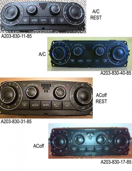
I am using the non digital one for now until I can find a Digital one. Connectors are plug in play.
Step 9:
Time to start Re-Assembling your console. Hook up the wire loom back to the Comand unit and double check your connections. Since there is a lot more wires, you will need to carefully tuck them under where the HVAC system goes as the comand system fills up the entire space. Be careful no wires come unplugged when doing this. Don’t Screw anything in yet, Just mount it.


Once mounted, Re attach your battery, Make sure your key is not in the Key Hole. Put your key in once the battery is attached, and switch it to second. (All the accessories should boot and the cluster will chime) Try powering on the Comand Unit one more time, See if it boots and loads. Also try your buttons, just check if you can lock/unlock. If both those work then your wireing is correct. Now try the HVAC, Turn just the fan to full speed, Wait for the car to adjust the flappers, See if you can feel the air coming out. If you can, Its correctly hooked up.

After you verified everything works, You can start screwing everything back in on the console.
Step 10:
After everything is back in its place, once more and make your way to the trunk. We now need to start removing the trim pieces on the Right side of the trunk. You will also need to remove the cover to the Rear Sam and TeleAid.

Once trim is removed, you should now be able to see the stock amp and harness connect ed to it. You will need to disconnect the harness and unscrew the Amp to pull it out. Once the amp is out, locate the fuse box on the left side of the trunk. It should have a little cover over it. Find where Fuse 7 goes; hook up your Multimeter, turn your car on to 2, Make sure your Multimeter shows 12+ or more. Turn your car off, Recheck the Multimeter make sure it shows 0 volts. Disconnect your battery.


Now take a 12 gauge wire 4ft (or little bit of speaker wire which is what I did, You just need one wire though) Strip both ends and crimp one end with a Flanged spade connector (Double check this fits into the fuse 7 socket on the Fuse box) and connect this end to the fuse box.

I ran the wire around some trim to hide it. I also added a fuse for precaution.

This wire is for the 12v Wakeup Power for your aftermarket AMP. (This is not the main power for the amp)
Step 11:
Stock AMP Harness, We now need to tap into this. Where the old amp is mounted there are 2 harnesses, Make sure you know the one you are taping into is the Stock amp one (The one with the connector to the amp)

Now there’s a bunch of wires on this harness but once you look at the wiring diagram is pretty easy to understand. Below I have listed it to make it easier
Sound Wires:
- 2 wires that are solid orange (positive) and orange with a brown stripe (negative) = Front Right (They are also for the tweeters)
- 2 Wires that are solid white (positive) and White with a brown stripe (negative) = Rear Right
- 2 Wires that are solid Olive Green (positive) and Olive green with a brown stripe (negative) = Front Left (They are also for the tweeters)
- 2 Wires that are solid pink (positive) and pink with a brown stripe (negative) = Rear Left
- 2 Wires that are Solid Purple (positive) and purple with a brown stripe (negative) = Bose SUB
- 2 Wires that are light solid blue (positive) and light blue with a brown stripe (negative) = Center Speaker
Miscellaneous Wires:
- Single Solid Brown Wire = Ground (Do not use the Factory Ground)
- Single Think Red Wire = Power (This one is always live if the battery is connect) (Please do not use this wire if you are not using the same amp I am using, as I did my research to make sure this would be compatible with out blowing anything on the stock harness)
You now need to cut all the speaker wires on the stock harness on the connector that I listed above. (If you are using the same amp I have, cut the main power wire as well) It should look like this:

I left a little room on the stock connector just in case I ever wanted to go back to factory. With your speaker wire you now need to splice both ends on the speaker wire and on the Stock Harness Speaker wires….(Not on the stock connector) You then need to solder the speaker wires (8 total remember) to the factory speaker harness. The picture below is an example but do not use Painters tape after you have solder, Use the heat wrap you bought or electrical tape, as in the picture I was testing the speaker system

After all stock harness speaker wires have been soldered and extended with regular speaker wires, Extend the factory power cable with the extra red wire you bought and solder those together. (Only do this if you are using the same amp, If you are using another amp make sure you have ran a separate power wire from the battery to the trunk.)
Find your other Black 8 Gauge wire that you bought (this will be your ground) Find where the ground port is (Should be pretty obvious its right next to where the old amp was, Bunch of other little things are ground there as well) and ground one end of this wire. Leave the other hanging.
Video: http://www.youtube.com/watch?v=8uaTr0syt08
Step 12:
Mounting the Aftermarket amp, This is all up to you where you mount it, As I don’t have a spare tire (Triple A) I mounted it there. The Foam base, On top I used “Fat Mat” so the amp would not melt into the Foam if it did get super hot. On the bottom of the foam base, I used Velcro so the amp would not be jumping around if I hit a bump along with wood blocks to screw the amp down to. Please consult your owner’s manual on the Amp for directions on setup and on the correct wiring for speaker cable hookup. Make sure you also hook up the RCA cables to the amp that you ran from the hi-low converter.
VIDEO: http://www.youtube.com/watch?v=1McWp0QX0eM
VIDEO: http://www.youtube.com/watch?v=_07eMW4sp3s


Step 13:
Double Check all connections. You may have to adjust the AMP, For Hi and Lows and a couple other things, again check your owner manual. Ensure you have all grounds connected. Once you have doubled checked, Connect your battery. Put your key in, and turn to # 2. Go to the truck to see if your amp powers up. If it does and you wired it correctly Turn on the comand system and try out your new amp
Video:http://www.youtube.com/watch?v=WbBar_wYa_A
Video:http://www.youtube.com/watch?v=DnGndW8cHkw
Hope this help guys...
Cheers!
If you Want an Auxiliary cable, Please follow this Guide. If not Go to Step 8.
https://mbworld.org/forums/c-class-w...e-warning.html
Step 8:
HVAC Control System (A/C and Heating) These wires remained unchanged and will not require any special modification. Please note though, Pre-Face lifted W203s with the Digital Control and or Separate passenger heating and Ac will need to find the digital version of the Face lifted that has the separate settings for the passenger control. You can use a standard Face lifted one, but only one side of the car will blow air and operate correctly. Here are the some photos of what you need. I took these from BF_JC230 Post so Credits to him.
I am using the non digital one for now until I can find a Digital one. Connectors are plug in play.
Step 9:
Time to start Re-Assembling your console. Hook up the wire loom back to the Comand unit and double check your connections. Since there is a lot more wires, you will need to carefully tuck them under where the HVAC system goes as the comand system fills up the entire space. Be careful no wires come unplugged when doing this. Don’t Screw anything in yet, Just mount it.
Once mounted, Re attach your battery, Make sure your key is not in the Key Hole. Put your key in once the battery is attached, and switch it to second. (All the accessories should boot and the cluster will chime) Try powering on the Comand Unit one more time, See if it boots and loads. Also try your buttons, just check if you can lock/unlock. If both those work then your wireing is correct. Now try the HVAC, Turn just the fan to full speed, Wait for the car to adjust the flappers, See if you can feel the air coming out. If you can, Its correctly hooked up.
After you verified everything works, You can start screwing everything back in on the console.
Step 10:
After everything is back in its place, once more and make your way to the trunk. We now need to start removing the trim pieces on the Right side of the trunk. You will also need to remove the cover to the Rear Sam and TeleAid.
Once trim is removed, you should now be able to see the stock amp and harness connect ed to it. You will need to disconnect the harness and unscrew the Amp to pull it out. Once the amp is out, locate the fuse box on the left side of the trunk. It should have a little cover over it. Find where Fuse 7 goes; hook up your Multimeter, turn your car on to 2, Make sure your Multimeter shows 12+ or more. Turn your car off, Recheck the Multimeter make sure it shows 0 volts. Disconnect your battery.
Now take a 12 gauge wire 4ft (or little bit of speaker wire which is what I did, You just need one wire though) Strip both ends and crimp one end with a Flanged spade connector (Double check this fits into the fuse 7 socket on the Fuse box) and connect this end to the fuse box.
I ran the wire around some trim to hide it. I also added a fuse for precaution.
This wire is for the 12v Wakeup Power for your aftermarket AMP. (This is not the main power for the amp)
Step 11:
Stock AMP Harness, We now need to tap into this. Where the old amp is mounted there are 2 harnesses, Make sure you know the one you are taping into is the Stock amp one (The one with the connector to the amp)
Now there’s a bunch of wires on this harness but once you look at the wiring diagram is pretty easy to understand. Below I have listed it to make it easier
Sound Wires:
- 2 wires that are solid orange (positive) and orange with a brown stripe (negative) = Front Right (They are also for the tweeters)
- 2 Wires that are solid white (positive) and White with a brown stripe (negative) = Rear Right
- 2 Wires that are solid Olive Green (positive) and Olive green with a brown stripe (negative) = Front Left (They are also for the tweeters)
- 2 Wires that are solid pink (positive) and pink with a brown stripe (negative) = Rear Left
- 2 Wires that are Solid Purple (positive) and purple with a brown stripe (negative) = Bose SUB
- 2 Wires that are light solid blue (positive) and light blue with a brown stripe (negative) = Center Speaker
Miscellaneous Wires:
- Single Solid Brown Wire = Ground (Do not use the Factory Ground)
- Single Think Red Wire = Power (This one is always live if the battery is connect) (Please do not use this wire if you are not using the same amp I am using, as I did my research to make sure this would be compatible with out blowing anything on the stock harness)
You now need to cut all the speaker wires on the stock harness on the connector that I listed above. (If you are using the same amp I have, cut the main power wire as well) It should look like this:
I left a little room on the stock connector just in case I ever wanted to go back to factory. With your speaker wire you now need to splice both ends on the speaker wire and on the Stock Harness Speaker wires….(Not on the stock connector) You then need to solder the speaker wires (8 total remember) to the factory speaker harness. The picture below is an example but do not use Painters tape after you have solder, Use the heat wrap you bought or electrical tape, as in the picture I was testing the speaker system
After all stock harness speaker wires have been soldered and extended with regular speaker wires, Extend the factory power cable with the extra red wire you bought and solder those together. (Only do this if you are using the same amp, If you are using another amp make sure you have ran a separate power wire from the battery to the trunk.)
Find your other Black 8 Gauge wire that you bought (this will be your ground) Find where the ground port is (Should be pretty obvious its right next to where the old amp was, Bunch of other little things are ground there as well) and ground one end of this wire. Leave the other hanging.
Video: http://www.youtube.com/watch?v=8uaTr0syt08
Step 12:
Mounting the Aftermarket amp, This is all up to you where you mount it, As I don’t have a spare tire (Triple A) I mounted it there. The Foam base, On top I used “Fat Mat” so the amp would not melt into the Foam if it did get super hot. On the bottom of the foam base, I used Velcro so the amp would not be jumping around if I hit a bump along with wood blocks to screw the amp down to. Please consult your owner’s manual on the Amp for directions on setup and on the correct wiring for speaker cable hookup. Make sure you also hook up the RCA cables to the amp that you ran from the hi-low converter.
VIDEO: http://www.youtube.com/watch?v=1McWp0QX0eM
VIDEO: http://www.youtube.com/watch?v=_07eMW4sp3s
Step 13:
Double Check all connections. You may have to adjust the AMP, For Hi and Lows and a couple other things, again check your owner manual. Ensure you have all grounds connected. Once you have doubled checked, Connect your battery. Put your key in, and turn to # 2. Go to the truck to see if your amp powers up. If it does and you wired it correctly Turn on the comand system and try out your new amp
Video:http://www.youtube.com/watch?v=WbBar_wYa_A
Video:http://www.youtube.com/watch?v=DnGndW8cHkw
Hope this help guys...
Cheers!
MBWorld Fanatic!
Joined: Nov 2007
Posts: 2,078
Likes: 4
From: NYC
2012 C300 4Matic
Awesome! Thank you for posting this!
I hope you don't mind a small change that I might suggest. I would use an add-a-fuse for that wake-up wire that you ran. That way you can have the fuse right there with the rest of them on the rear SAM and avoid the spade connectors.
I hope you don't mind a small change that I might suggest. I would use an add-a-fuse for that wake-up wire that you ran. That way you can have the fuse right there with the rest of them on the rear SAM and avoid the spade connectors.
Trending Topics
MBWorld Fanatic!

Joined: Jan 2006
Posts: 3,212
Likes: 8
From: Pasadena, CA
2002 C230K, 2013 BMW 328, 2015 BMW X5
This is a great write up. The utility of how you have labeled the connectors will be helpful for anyone doing a wiring project in a vehicle.
Are you going to use the features of the phone integration?
Ed
Are you going to use the features of the phone integration?
Ed
MB World Stories
The Best of Mercedes & AMG

Manual Mercedes? 6 Times Sindelfingen Let Drivers Have All The Fun
Verdad Gallardo
Mercedes SLR McLaren 722 S Is Extremely Rare Example Modified by McLaren
Verdad Gallardo
8 Classic Boxy Mercedes Designs That Have Aged Like Fine Wine
Verdad Gallardo
Flawlessly Restored Mercedes 190E Evo II Heads to Auction
Verdad Gallardo
Electric Mercedes C-Class Unveiled: 11 Things You Need to Know
Verdad Gallardo
Mercedes EQS Gets A Major Update: Everything You Need to Know
Verdad Gallardo
5 Underrated Mercedes-Benz Models That Don't Get the Love They Deserve
Verdad Gallardo
Mercedes 300D Has Pushed Well Past 1 Million Miles and It Ain't Stopping
Verdad Gallardo
10 Most Reliable Mercedes-Benz Models You Can Buy Used
Verdad Gallardo
Thread Starter
Super Member
Joined: Oct 2007
Posts: 569
Likes: 0
From: Bay Area, CA
Volvo
I could but, I may just upgrade my Comand to the 07 model, that way i can have bluetooth. I plan on doing the digtial swap to the HVAC and to added the 6 disk cd changer that supports MP3. Since everything is now wired, its very easy to add
MBWorld Fanatic!
Joined: Jan 2006
Posts: 3,212
Likes: 8
From: Pasadena, CA
2002 C230K, 2013 BMW 328, 2015 BMW X5
With your solder skills, I wonder how difficult it would be to find the amp portion of the Command unit, and tap into whatever signal goes into it. Of course, I don't have a donor Command unit to hack up.
")
Ed

Thread Starter
Super Member
Joined: Oct 2007
Posts: 569
Likes: 0
From: Bay Area, CA
Volvo
Having gone this far into it, how about creating some RCA outs from the head unit? I have always been a bit iffy on the use of line level convertors.
With your solder skills, I wonder how difficult it would be to find the amp portion of the Command unit, and tap into whatever signal goes into it. Of course, I don't have a donor Command unit to hack up.
Ed
With your solder skills, I wonder how difficult it would be to find the amp portion of the Command unit, and tap into whatever signal goes into it. Of course, I don't have a donor Command unit to hack up.
Ed

Thread Starter
Super Member
Joined: Oct 2007
Posts: 569
Likes: 0
From: Bay Area, CA
Volvo
Chris, Its pretty easy, You need to remove the faceplate underneath the Glvoeboth (4 screws Torx) then there are 3 screw you will notice holding the glove box in. Then on the side of where it looks like theres a passanger side fuse box, open that up, and there are 2 screws in there. You then need to open the glove box, Remove the 6disk cd changer, as there are 2-3 screws holding the glovebox uptop. After that, it should come out
Super Member
Joined: Jan 2005
Posts: 952
Likes: 0
From: Chula Vista, San Diego
c230 Kompressor Coupe
Chris, Its pretty easy, You need to remove the faceplate underneath the Glvoeboth (4 screws Torx) then there are 3 screw you will notice holding the glove box in. Then on the side of where it looks like theres a passanger side fuse box, open that up, and there are 2 screws in there. You then need to open the glove box, Remove the 6disk cd changer, as there are 2-3 screws holding the glovebox uptop. After that, it should come out


MBWorld Fanatic!


Joined: Jan 2007
Posts: 1,986
Likes: 9
From: Toronto
V12TT
I have the 05-07 full console for sale if anyone is interested. Includes the wood trim. I prefer local pickup. I'm in Toronto...
http://www.puremb.com/forum/showthre...-FOR-SALE!-250
http://www.puremb.com/forum/showthre...-FOR-SALE!-250


