When you click on links to various merchants on this site and make a purchase, this can result in this site earning a commission. Affiliate programs and affiliations include, but are not limited to, the eBay Partner Network.
Battery-Alternator Warning Light - Where should I look for damage?
When I was working on another issue, I dropped a socket wrench. One end landed on the alternator power cable and the other touched the frame. I saw a spark and heard a pop.
When I started the car, I had a battery-alternator warning:
Warning message
My initial reaction (in addition to being angry at myself) was that I had damaged the alternator. I removed the alternator and took it to an alternator shop and the owner tested it and said it was working fine. Based on my description of the accident, he suggested that I might have damaged a fuse or other component in the battery-alternator circuit. Since I have access to a parts car, I picked up the distribution block that is connected to the battery and replaced mine. (It is my understanding that it contains fusible links and I thought I could have damaged one or more of them.) Distribution block
That didn't solve the problem. The car starts fine. When I start the car and watch the voltage reading on the center screen, I start at 12.4 volts. While the starter is turning, it reads slightly under 12 volts. When the car is running, it reads 12.1 or 12 volts. The battery seems to be holding a charge well and it is about 2-years old.
I'm seeking suggestions on the next place to look for a damaged component. I checked the fuse diagram, and I could not find a fuse listed for the alternator.
The system returned code 2062-002 - Alternator serial interface. No connection to the control module
N3/10 (ME-SFI [ME] control unit)
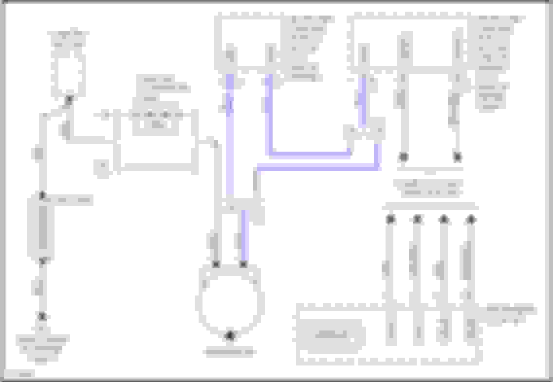
Based on the diagram, this seems to suggest that there was:
1. Damage to the blue wire that attaches to the control module
2. (Worse case scenario) a damaged control module.
3. Damaged connector to the alternator
4. Damaged voltage regulator on the alternator itself since this attaches to the blue wire.
Any suggestions on my next step? At this time, I am ruling out replacing the alternator pending the results from other trouble-shooting.
Hantek 1008C 8CH Automotive Diagnostic PC Oscilloscope 2.4MSa/s USB 2.0 bandwidth 100K Program Generator
Price: $93.90
Note, it's from a China company, and *I* wouldn't suggest installing their software on your main PC.
Imho, I'd prefer a National Instruments USB scope (~$200+) instead. Or, a PicoScope (~$800++).
However, I wouldn't need either, since I have a "number" of storage oscilloscopes, etc. (That's what I do.)
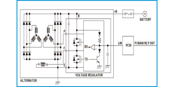
That single wire is a LIN bus wire.
So, you need to see:
A) If LIN-bus data is going from the SAM to the module(I expect it is).
B) If LIN-bus data is going back from the module to the SAM(I expect it is).
C) Is the LIN-bus data going from the module to the Alternator.
D) Is the LIN-bus data back going from the Alternator to the module.
Thanks again for your reply. I'm not quite ready to buy an oscilloscope, but I'm beginning to think it may be necessary.
Since my last update I decided to take a chance and see whether the voltage regulator was damaged. I replaced it, but it did not fix the problem.
I checked the voltage at the alternator with the car running and it was negligible - approximately 0.4 volts. I connected the STAR system and it read the same fault code I posted previously - 2062-002 - Alternator serial interface. No connection to the control module. When I ran the STAR system, there were menu choices for alternator testing, but they would not run on my system. (Jake and I bought the system used and I don't know much about its origins. It may be a Chinese clone.) I've posted a video showing what happens when I attempt to use the alternator diagnosis menu. If you pause it at about the half-way point you should see a message that says, "DAS and WIS are active at the same time. It is possible to switch over between the systems with the key combinations ALT + TAB." I'm not sure whether doing that will allow the test to run, but I will give it a try later.
I've also posted photos showing the data connector and the battery connector to the alternator and the voltage regulator that I removed. I cannot see any visible damage. Data and battery connections Voltage regulator removed from alternator
I think the problems could be: 1. Damage to another part of the alternator 2. Damage to the communication system between the ECU and the alternator which is preventing the alternator from receiving a signal to turn on.
I was thinking of buying this: https://www.harborfreight.com/Comput...obe-63597.html and using it to probe the connection from the ECU to the alternator. My thought process is that it will show whether there is a signal coming from the ECU.
I could buy a rebuilt alternator, but before I do that I want to be sure it is the problem.
That part you linked to from HF is just a test light.
It's not a logic probe.
You're correct that seeing if there is any data traffic can often be useful and informative.
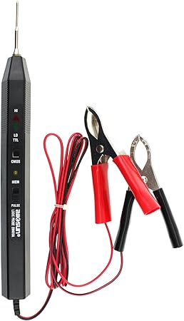
You want a real logic probe, that can detect and show pulses, like the following one :
This logic Troubleshooting instrument will give visual (LED light) and audio indications for logic levels and pulses
It can also capture positive or negative events as short as 30 nanoseconds
Portable size but easy to operate
IMHO, an ~$99 compact USB 'scope is a better investment, and you won't be constantly throwing good money after bad.
All you have to do is hook up the scope, capture the data traffic (zoomed in enough so that we can see each bit time), then post the image.
I can then easily tell you if there is any response data.
It's actually the simplest data traffic, and very easy to debug. Traffic like CAN, RS232, etc, require decoding each packet, knowing what the codes and fields are, etc.
For the LIN-bus, you can tell by the length of the packet.
At the start of a LIN bus packet, the master sends 55. That has the bus toggle between 1 and 0. You measure how long each 1 or 0 is, and that gives you the bit-time and data rate.
For a short packet like this, it can all be done visually.
Then, the length of the packet will indicate if there is any response.
You test the path from the SAM to the module first. That should have both the first Command section, and the second Response section.
You would then also know and verify that your scope is setup properly.
BTW, the chance that the setup you have is _not_ a China clone is about the same chance that a Mars size asteroid will impact the Earth in the next 5 mins.
Watch out! ;-)
The point is, that you can _not_ say 'without a doubt' that IN FACT that is a China clone. You do not have the experience, nor knowledge in that area.
It's a fine legal point, but it is true.
Note, that would not protect a 'professional' (anyone that takes any type of payment), using that on a car.
The above is also different than buying illegal drugs from some dude on a dark street.
No reason for not knowing that was not legal.
Thanks again for your advice. You are correct that there is no way to know whether Jake and I have a clone or not. The auction seller said it wasn't made in China (which is not quite the same as saying it wasn't a clone) and if you can't trust an on-line auction seller who can you trust? Here's a link to the auction if you are interested: Not a clone Even if it is a clone, it has worked well enough that I've already saved enough money by fixing a problem with my front SAM to justify my share of the purchase cost. I do need to wrap up this repair so that I can ship the machine off to Jake and enable him to work on his projects.
I'm beginning to feel like I did in college when I was taking a math class that was more challenging than I expected. I remember say something like, "This is hard" while I was studying. One of my room mates picked up the book I was using and said, "This isn't hard, you're just stupid." (He was a philosophy major and really didn't know what he was talking about.)
I'm planning to take the same approach I took to solving my problem with the math class. I will be re-tracing my steps and determining whether there was something I missed. (For the math class I figured out that I needed to devote about 3 times as many hours to solving practice problems than I had been spending.) One question I have regarding the alternator is whether I can trust the conclusion I obtained when I took the alternator to a local rebuild shop. The shop owner put the alternator on his test machine and said that it was a good alternator. He also told me that he didn't work on Bosch alternators because he couldn't get parts for them. His shop had piles of alternators and starters around and he clearly had years of experience with rebuilding motors. But, I'm wondering whether his test machine (which seemed like it was about 20-years old) and his lack of specific experience with Bosch could have caused him to miss a problem with the data communication.
I have also been receiving advice from a non-Mercedes forum 2 Car Pros They suggested a couple of more trouble-shooting steps. If those don't tell me anything, I plan to take the alternator off the car and have it tested at Advance Auto. That will help me to decide whether to try a rebuilt alternator or purchase an oscilloscope. I've been reviewing the information you provided and while it is a little bit outside of my comfort zone I think I can learn how to use an oscilloscope with a little help.
I could also take the car to a shop. My concern with that option is that their first step will be to install a new alternator and charge about $800.
Fortunately, I have another car and I have time to sort this out.
Last edited by KevinH2000; Jun 21, 2020 at 10:47 AM.
One more piece of data. I checked for continuity in the data wire that runs to the alternator. My (admittedly limited capability equipment) appears to show that the data wire is receiving power.
The flash makes it difficult to see, but the red LED is illuminated in the test light. This photo was taken without flash. It's a little blurry, but it's easier to see that the red LED is illuminated. No obvious damage to the part of the wire that I can see. I cannot see any damage to the connector.
I'm not sure what this is telling me. My thoughts are that I would not be seeing the red LED indicating that there is power if there is a break in the line. That does not mean that the alternator is receiving the correct signal from the ECU or the SAM. I scanned the front SAM and there is no fault code in it. The only fault code in the ECU is the one I posted above.
Right now, I'm planning to remove the alternator and have it tested again. Advance Auto appears to have a more sophisticated machine than the one at the rebuild shop and that may tell me more.
On a different but related topic - I'm wondering whether something is missing from the STAR system I bought with Jake. I don't see an icon for the WIS:
Last edited by KevinH2000; Jun 21, 2020 at 12:29 PM.
This is a typical example of little or no knowledge of a basic charging system function!
forget about fancy tools and scopes. Apply some logic here. You dropped a tool that shorted the main supply cable. How does this damage an alternator? When the short is effectivley before the input. Did you bother to test if you have battery voltage at the alternator main supply
output with a simple test lamp?
I suggest that you re-read the above posts.
We are not talking about some Model-T.
One more piece of data. I checked for continuity in the data wire that runs to the alternator. My (admittedly limited capability equipment) appears to show that the data wire is receiving power.
The flash makes it difficult to see, but the red LED is illuminated in the test light.
This photo was taken without flash. It's a little blurry, but it's easier to see that the red LED is illuminated.
Does the light flash at all?
I'd be surprised if you saw any flashing. Even if the bus was functioning properly.
It has to do with the duty cycle of the low-voltage pulses, and the delay of a bulb (or LED) turning off.
There's a long history of digital voltage and electronics standards.
The LIN-Bus is an "open-collector" bus. It's normally high (5V).
The bus (single-wire) is connected to 5V via an ~1K-ohms to 10K-ohms pull-up resistor.
The separate devices pull the bus to "ground".
This way, there can be many devices that can drive the single-wire (common bus).
Also, be careful of reading "high", "low", "1", "0", "asserted", "not asserted", "asserted high", "asserted low", "true", or "false" in any articles or forums.
Many times, people make mistakes, typos, are just plain wrong, and so on.
Again, there's a long story of standards, and reasons.
The most common serial bus is RS232. There, the low-voltage is a "1", the high-voltage is a "0".
For various historical reasons, many designers, and standards, use "asserted low".
Where the low-voltage is a "1", and the high-voltage is a "0".
The question is.... Did you check for battery voltage at the alternator MAIN supply?
Is there battery voltage there? Yes or no.
for this test all that is needed is a test lamp.
if the Answer is No then the fuse is blown for sure!
The question is.... Did you check for battery voltage at the alternator MAIN supply?
Is there battery voltage there? Yes or no.
for this test all that is needed is a test lamp.
if the Answer is No then the fuse is blown for sure!
I am out of town. I plan to do this when I return home later today.
I checked the main supply with the alternator in the car and I got a green light for ground. I didn’t think to remove the battery cable from the alternator and check it that way.
A blown fuse was one of my first suspects. I checked all the fuses in the front SAM and they were OK. Here’s the best fuse/relay/fusible link guide I could find: W203 diagram I thought I had damaged one of the fusible links, and I replaced the pre-fuse block with one from a parts car I have access to. I am going to double-check my work and see whether I missed anything. If there is another fuse somewhere that I need to check, I hope somebody can tell me where to find it.
Because I had to replace the SAM to fix a turn signal problem, I have a full set of relays available. It appears that relay “S” in the linked diagram is a possible culprit, so I will go ahead and swap it.
Last edited by KevinH2000; Jun 22, 2020 at 08:22 AM.
Well you see you already found the fault!
there must ALWAYS be 12v at the alternator main supply. There is a fusable link in the cable between the starter and alternator and it blew when your tool shorted the supply. You need to replace the cable to the alternator now to fix your issue.
your faults will go away and it will then charge.
good luck
I checked the cable at the alternator with a test light. As Russell predicted there was no power.
Now I have to figure out how to gain access to the fusible link. I think I can see where it is. Working on it is a different matter. I have started studying the starter replacement procedures on the M271 engine for clues. If anyone has suggestions for a procedure please let me know.
It's not too bad a job. Just remove cable from starter and over bell housing to alternator
The term "not too bad a job" must mean something different for you than for me. The configuration of the M271 engine required me to (1) Dismount a refrigerant line, (2) Detach a steering coupling and (3) Partially detach the supercharger dampener. Then, I had enough room to put a 13mm wrench on the bolt holding the battery/starter/alternator wire in place and remove it.
Once I had the bolt off, I was able to pull it over the bell housing. I had to open up the protective casing to access the 175-amp fusible link. Then, I verified that the link had blown with my test light. The battery side of the link had power:
The other side did not.
Unfortunately, it does not appear that a replacement link can be swapped in. I searched on the term "175-amp fusible link" and couldn't find anything that looked like the one in the car. The fusible links that my search identified had different configurations. It looks like the one Mercedes used was crimped on using a machine that could generate a significant amount of force.
Note how the fusible link is crimped in place.
I want the repair I make to be reliable although I can find 175 amp fusible links, they look like this:
If I use a fusible link like this, I need to find a way to install that won't allow it to come loose over time. A better option may be to replace the entire cable with one from a recycling yard. I have access to a C230 that I used to harvest replacement parts. Unfortunately, it is sitting on flat tires in the owner's back yard. To remove the bolt on the starter, I must get under the car and I cannot think of a safe way to do that.
I found one on an auction site for a coupe, but the listing doesn't confirm that the cable will fit a sedan. I may take a chance and buy it anyway.
I work on them daily so thats why I say it's not to bad a job. Also here it's only right hand steering so without the steering shaft it does make the job a bit easier. Regarding your repair. You have 2 options. Either replace the cable complete. Or make up a new cable without a fuse. I dont think a repair will be reliable. You will need extremely good connections for it to work properly.
I already made one mistake and I didn’t want to compound my error with a poor-quality repair. I couldn’t think of a way to mount a fuse holder in the existing cable that would provide reasonable assurance of long-term reliability. The “solid wire” solution did cross my mind, but (as I proved) the fusible link is there for a reason.
I decided to replace the cable. I had to splurge on a new one. I couldn’t find a used one at the local recycling yards. The only cable I found on eBay in the U.S. looked like it had seen rough handling. There was a nice one listed in Latvia at a good price, but I need to get the car back on the road soon.
Last edited by KevinH2000; Jul 2, 2020 at 07:49 AM.
I installed the new battery/starter/alternator cable. (If anyone else ever needs to do this, here's a link to the the instructions: Starter Replacement - M271 ) There are also videos on YouTube. The cable has to fit between the starter and the engine block or the cable end will block the reinstallation of the supercharger dampener. Look at the routing of the cable as you remove it, and you will see how to do it. It may be easier to route the cable if you remove the starter. I did not remove the starter because I couldn't remove one of the bolts holding it in place due to the size of the head of my ratchet. If I have to replace the starter, I will need to buy a ratchet with a more compact head or use a combination of a swivel and extensions to access it. I saw some people claim that they did not need to remove the supercharger dampener to access the bolt holding the cable on the end of the starter. I don't see how they did that. In addition to the dampener, I had to disconnect the steering linkage and move a refrigerant line.
To make a long story short, I now have power to the alternator. Unfortunately, I still have the alternator-battery warning light. When I display the voltage on the center information screen with the car running it shows 12.1 volts instead of the 14-14.2 volts it would display before I damaged the system.
When I connect the STAR tool, it displays the same fault code as it did before I replaced the cable - 2062-02-Alternator Serial Interface - No connection to the control module. As noted in previous posts, the data line to the ECU has continuity. However, I have not used an oscilloscope as Red Gray suggested to read the data.
I had previously had the alternator tested at a rebuild shop on a somewhat primitive looking machine. The technician gave it a passing grade. I replaced the voltage regulator on it because the brushes were worn. I had it retested at an Advance Auto and they said it failed. The Advance Auto test machine is capable of printing out data, but the technician didn't know how to do it. He did tell me the voltage regulator was OK.
It looks like my next step may be to replace the alternator with a rebuilt unit. Before I spend $200 throwing another part at the car, does anyone have other suggestions? I think my second option would be to follow Red Gray's advice and either obtain an oscilloscope to read the data or find someone who has the equipment and can do it for me.
I'd suggest a rebuilt alternator.
While using Google, I went down a rat hole that lead to a ?MB SUV? where the person disconnected the LIN serial line, and the alternator still "worked fine".
That's what I'd expect/hope. Cars should have at least half-decent fail-safe modes.
Also, do the Autozone/repair place have to connect the LIN bus?
My guess is that they do not.
I'd expect that they use a motor and belt to turn the alternator, and connect the alternators main output to a load, and measure.
Does the battery voltage go up at all after you start the car?
If not, and the battery cable is connected to the alternator fully :-), the only other thing would be if MB uses an external voltage sense/feedback line for the alternator. I don't remember seeing one.
You could try a cheap logic probe instead of a scope.
Still, I think that a rebuilt alternator is a better bet.
Mercedes SLR McLaren 722 S Is Extremely Rare Example Modified by McLaren
Slideshow: A one-of-one U.S.-spec Mercedes-Benz SLR McLaren Roadster became even rarer after a factory-backed transformation at McLaren's headquarters.