When you click on links to various merchants on this site and make a purchase, this can result in this site earning a commission. Affiliate programs and affiliations include, but are not limited to, the eBay Partner Network.
I was told my car already had the control unit for the illuminated star by the dealer. Than the quoted me 812 to supply and install. Part numbers were 166-817-75-00(star) and 205-820-44-00(wiring harness). They were unable to tell me what functions the star would have?. They told me I was lucky to have control module being that they want 400 for that. I have 2017 c300 sedan. Not sure if anyone else has info on how this setup functions on this vehicle?
$812 is still a lot when you can easily diy for under $100. Order the illuminated star from amazon or ebay for $50-$80. Order a fuse tap and 5amp fuses for $10. Load the fuse tap with two 5amp fuses and insert into slot f123b in the engine compartment fuse box. You will need to drill a small hole for the wire. Install the star and wire it up. It comes on when the headlights are illuminated. Use the following diy as a guide but use a fuse tap instead of the methed shown...it's so much easier. https://mbworld.org/how-tos/a/merced...ed-star-384223
I own a Mercedes-Benz C300 2015 and I ordered the star from ebay and could not make it work. I followed the guide step by step on https://mbworld.org/how-tos/a/merced...ed-star-384223. do you think by fuse tapping it will work? can you advise?
Provide a DIY guid for installing illuminated star in your W205. This guide is for car without the Driver Assistance Package (Distronic Plus) Code 997 option.
Let me know if you have any questions.
LED illuminated star
wire harness assembly
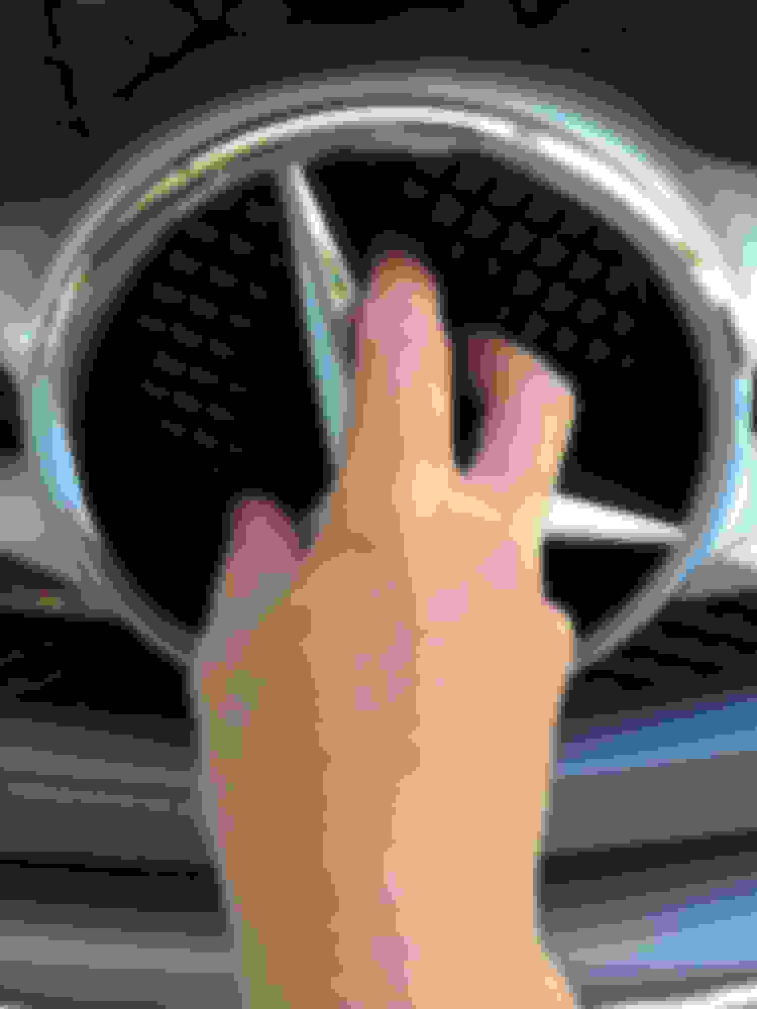
Remove the star counter clockwise from the grill
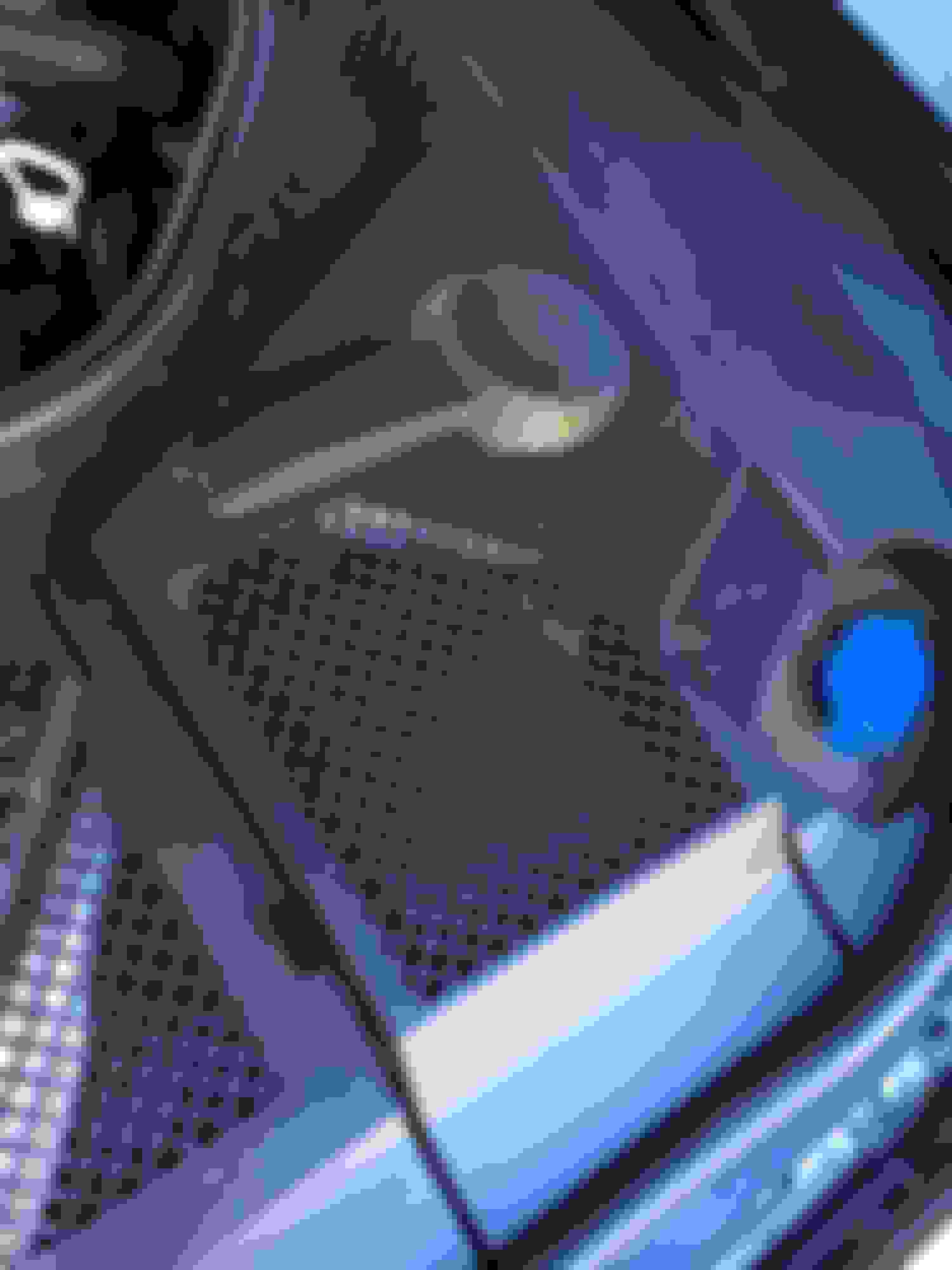
Locate your engine fuse box in you driver side
Remove the plastic cover and expose the fusebox
Use a Torx screwdriver and remove the 2 screws and remove the top cover. Use a pry tool to carefully pry back side of the fuse/relay module
Life up the edge of the fuse/relay module. There is sufficient wire underneath so you can pull the entire module out and set it aside.
-Mark center of the top side edge and place another marker 1 inch down. Drill a 3/4" hole<br/><br/>-Route your red wire that comes with the kit through hole in grommet
In the back of the fuse/relay module, locate the S8 connector and connect the red wire to position 8 of the connector
Reinstall the fuse/relay module back to the box and install a 5A fuse into position F123 (B)
Remove plastic rivets (1) that secure the radiator support panel
Remove plastic rivets (2)
Remove plastic rivets (3)
-Route the cable towards to the center of the radiator<br/><br/>-Route the ground cable towards to the passenger side
Connect ground wire to ground terminal (passenger side)
Connect the star wiring harness
Reassemble in reverse order.
I don't see that your illuminated star package includes a control unit. Can you share a DIY for an illuminated star with a control unit. I understand that if my package has a control unit the star will go on only when i lock unclock the car and will turn off when i start the engine?
So here is a picture of the instructions that came with my after market LED star that I bought from eBay. Can anyone help me identify where does the positive wire and negative wire connect to and where does the black line/signal wire connect to? The picture is not clear and very telling in the diagram.
My thought is that the positive electrode connects to the positive end of the battery and the negative to the negative end of the battery and then the signal wire taps into the fuse 108 or 110 for the headlights so that the star comes on only when the headlights are on and not as DRL's, but again this is just my inference and conclusion from this diagram. Any good electrical engineers out there who can help out, would be highly appreciated
it appears this setup is similar to a dash camera hard wire install.
+ Electrode = goes to battery + positive - Electrode = goes to battery - negative OR any properly grounded screw in engine bay.
ACC = tap a fuse that only has power when the cars accessories have power OR when the engine is running. Your choice. (this is only to switch your star on/off)
As a test (before installing) you could connect the - and + wires to the battery, and then touch the ACC wire to + positive battery terminal to see if star turns on/off.
Thanks brother for the info. I did assume this but I wanted to also know how to make the star come on with the headlights at night on auto or when I turn them on manually. I assume that to do that, I just connect the acc wire to the headlight fuse instead of the accessory or ignition fuse, correct? Yes i have already ordered the fuse tap a few days back.
Also, i think the main battery on a 2015 c300 is in the rear i think and only the aux battery is in the front so is it ok to connect it to the front battery?
Just waiting for someone to confirm that I am in the right direction and I will go to town with this diy. The seller, unfortunately retains from giving any instructions 😔
Worked perfectly on my C Class. Just follow the instructions and you're all set.
Did you install a oem or after market star? If after market then how did you connect the wires to have the star on only once the headlights come on and off when the lights are off?
it appears this setup is similar to a dash camera hard wire install.
+ Electrode = goes to battery + positive - Electrode = goes to battery - negative OR any properly grounded screw in engine bay.
ACC = tap a fuse that only has power when the cars accessories have power OR when the engine is running. Your choice. (this is only to switch your star on/off)
As a test (before installing) you could connect the - and + wires to the battery, and then touch the ACC wire to + positive battery terminal to see if star turns on/off.
Disclaimer (I am making these assumptions based on the information you provided)
YOU COULD ALSO ASK THE SELLER TO BE SURE.
Thanks for these directions man. I followed these and was able to get it working and i used fuse 113. Another member listed that this fuse activated only when the car is operational and he said it is controlled by the sensors that control the headlights so this doesn't turn on during the day. Just installed it at night so I'll check it out tomorrow during the day and report back. I had the star lying around since the last 1 year and shops were quoting me $100/hr to install it and figure it out. I refused to give $100 for a $80 product lol.
This YouTube video is for the OEM star which is much straight forward to install and comes with instructions. The eBay seller that i bought it from didn't send instructions and wasn't willing to help out either. I pulled the instructions from another similar product that had it pictured on their eBay page.
Finally got around to installing the Star after having it sit in my garage for 1 year and contemplating if I can do it without any instructions provided or should i get a shop to do it for $100 or so. Glad i used some common logic and some help from a member on the forum and i was able to do it in 15 minutes!
Provide a DIY guid for installing illuminated star in your W205. This guide is for car without the Driver Assistance Package (Distronic Plus) Code 997 option.
Let me know if you have any questions.
LED illuminated star
wire harness assembly
Remove the star counter clockwise from the grill
Locate your engine fuse box in you driver side
Remove the plastic cover and expose the fusebox
Use a Torx screwdriver and remove the 2 screws and remove the top cover. Use a pry tool to carefully pry back side of the fuse/relay module
Life up the edge of the fuse/relay module. There is sufficient wire underneath so you can pull the entire module out and set it aside.
-Mark center of the top side edge and place another marker 1 inch down. Drill a 3/4" hole<br/><br/>-Route your red wire that comes with the kit through hole in grommet
In the back of the fuse/relay module, locate the S8 connector and connect the red wire to position 8 of the connector
Reinstall the fuse/relay module back to the box and install a 5A fuse into position F123 (B)
Remove plastic rivets (1) that secure the radiator support panel
Remove plastic rivets (2)
Remove plastic rivets (3)
-Route the cable towards to the center of the radiator<br/><br/>-Route the ground cable towards to the passenger side
Connect ground wire to ground terminal (passenger side)
Connect the star wiring harness
Reassemble in reverse order.
Newbie question so not sure if I am breaking any rules...
I have a query regarding how to connect the wire to pin 8 of the S8 connector. When I stick it in it keeps falling off.
So I had boughten my illuminating star from Amazon. It came only with Red and Black wire. I spliced the Red wire to the grey/yellow wire of the headlight on the driver's side and the black wire to the body of the car. I saw these instructions on a W205 post but it is not working for me... anyone have any ideas? https://mbworld.org/forums/c-class-w...iring-yet.html
So I had boughten my illuminating star from Amazon. It came only with Red and Black wire. I spliced the Red wire to the grey/yellow wire of the headlight on the driver's side and the black wire to the body of the car. I saw these instructions on a W205 post but it is not working for me... anyone have any ideas? https://mbworld.org/forums/c-class-w...iring-yet.html
Why would you splice it? Just connect the red to positive and black to negative and the 3rd one to a fuse and you should be good to go.
I don't see that your illuminated star package includes a control unit. Can you share a DIY for an illuminated star with a control unit. I understand that if my package has a control unit the star will go on only when i lock unclock the car and will turn off when i start the engine?
Hi, attached instruction but in italian (i'm italian ) directly from mercedes ASRA


 06-24-2015, 06:27 PM