When you click on links to various merchants on this site and make a purchase, this can result in this site earning a commission. Affiliate programs and affiliations include, but are not limited to, the eBay Partner Network.
I’ve noticed oil residue in the turbo inlet pipe and turbo compressor after few months of driving and this is caused by the oil vapor return pipes from the air/oil separator on top of the engine. Likely have oil residue in the intake manifold as well.
As i have done an oil catch tank setup in my previous C with great benefits (dry intake and no chipping of the compressor wheel fins), I have decided to attempt the same for the CLS.
So sharing some info as i will be installing a pair of oil catch tanks to the M256 engine setup (see attached pic)
First tank will take over the existing wide open ventilation setup and will be vented to atmosphere. (yes i know, bad for environment. Those concerned can route back to intake)
The cast turbo inlet holes (2 holes) and the charge pipe (1 nipple) needs to be capped. In the interim, i will use a metal plate with liquid gasket to seal the turbo inlet holes first, while i am making a new custom 3” inlet housing/flange. This housing will pair with a new 4” intake system.
Second tank will be connected inline of the partial load breathing hose (so its “pressurized”)
happy to discuss further with the experts here if there can be other alternative routing or setup.
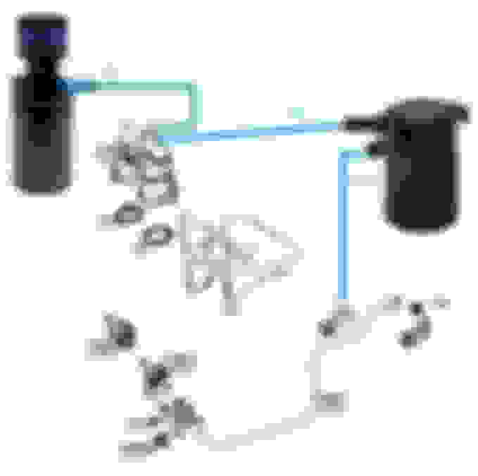
Here�s the latest updated schematics for the M256 oil catch tanks setup after the actual works are done.
Red box 1 (item 50) - existing wide open throttle ventilation hose set is removed. We route from the oil separator large port to a single inlet port OCT with VTA filter. Existing holes on turbo inlet pipe and charge pipe are plugged.
Red box 2 (item 150) - existing hose is removed, bottom tee is removed and plugged (circled orange) as this line is connected to item 200 for fuel vapor purging.
Red box 3 (item 100) - existing hose is removed. Plug OCT inlet hose to the top oil separator small port. At bottom connector remove the original hose and plug a new hose (circled blue) which will route to the OCT outlet port.
Please see the updated schmatics. Will share photos later on.
below is the final routing with the oil catch tanks.
car started with no issues, will drive around and see if any issues down the road and will check back to see if there will be any further oil stains on the turbo inlet pipe.
I�ve noticed oil residue in the turbo inlet pipe and turbo compressor after few months of driving and this is caused by the oil vapor return pipes from the air/oil separator on top of the engine. Likely have oil residue in the intake manifold as well.
As i have done an oil catch tank setup in my previous C with great benefits (dry intake and no chipping of the compressor wheel fins), I have decided to attempt the same for the CLS.
So sharing some info as i will be installing a pair of oil catch tanks to the M256 engine setup (see attached pic)
First tank will take over the existing wide open ventilation setup and will be vented to atmosphere. (yes i know, bad for environment. Those concerned can route back to intake)
The cast turbo inlet holes (2 holes) and the charge pipe (1 nipple) needs to be capped. In the interim, i will use a metal plate with liquid gasket to seal the turbo inlet holes first, while i am making a new custom 3� inlet housing/flange. This housing will pair with a new 4� intake system.
Second tank will be connected inline of the partial load breathing hose (so its �pressurized�)
happy to discuss further with the experts here if there can be other alternative routing or setup.
Cheers.
Interesting thread. M177 V8 seems to be developing a reputation for rear main oil seal failure due to excessive crankcase pressure from failed oil-vapor separators.
Catch cans, while potentially effective, are a band aid for junk MB engine design.
question, does VTA make the car run worse? I saw many people writing that by doing so the air intake will have less pressure and will run ruff and lean, causing less horsepower, also it would be nice if you were able to make a video on insta or YT showing how it was done, because you are the first person from what I have seen to make a catch can for this engine. also what do you think of the weistec VTA
thank you for your input
The VTA should not make the car run "worse" or cause less power.
Our mercs run on MAP and not MAF, so going VTA doesnt cause the lean condition.
Hi all, its been a while now and happy to report back that the catch cans are doing its job.... here is the amount of oil captured at every oil change..
have opened up my charge pipes and intake manifold and they are definitely dry now...
Hope this is helpful for those keen to embark on this setup
Hi, wondering why it needs two can?
A bit confused as I only have the knowledge of simpler set up, e.g. PCV -> catch can -> air intake. I replaced my Jeep with single line.
Hi, wondering why it needs two can?
A bit confused as I only have the knowledge of simpler set up, e.g. PCV -> catch can -> air intake. I replaced my Jeep with single line.
Appreciate if you could elaborate..
Thats because there are 2 breather lines for the Mercedes engine;
- one links to the air intake and usually this line has very little oil capture,
- and the second line connects back to the intake manifold which usually has more oil capture.
The one to the air intake i have set it up for "vent to atmosphere" and the latter i set it up "in-line" so it doesn't affect the manifold vacuum/boost.
I did the same 2 can setup to my C Class W205 2L (M274) engine cos it has 2 lines as well.
Hope this clarifies.
Two cans are needed because intake pressure is either vacuum (unboosted at low engine power) or pressure (boosted at moderate and higher engine power). The two-path oil vapor separation system can be seen on MB and Porsche engines.
From memory one vapor entry point is downstream of the throttle body (unboosted path) and the other is close to the turbocharger inlet (boosted path).
A single can solution could be used with an appropriate network of check valves. A two can solution requires less valving. A two can solution offers higher separation capacity in terms of cfm or ml of oil over time.
M17x problems with rear main seal failure seem to relate to a one-size-fits-all approach by MB when sizing the OVS components. M17x has at least 4 power levels but OVS components are generally the same size. An engineering mistake by MB. OVS components should be sized for the amount of blowby created by the engine, which is proportional to power.
Does anyone know of a thread on here or have advice on how to apply an oil catch can on an M271 engine? I've seen a couple variations, but nothing concrete. I understand I've seen Glyn Ruck on here speaking against the oil catch can systems, but my factory PCV valve (which I replace a year ago) isn't doing the job.
I'm still accumulating a lot of oil in the intake manifold, supercharger, and thus the throttle body. (2005 C230K SS) I understand that my vehicle is 160,000 miles and the piston rings are likely worn causing this issue, but I've done all that I can think of. As you can see below, I'm pretty thorough on my maintenance and repairs.
Last edited by Norsk_Johnson; Mar 6, 2025 at 12:10 PM.
Does anyone know of a thread on here or have advice on how to apply an oil catch can on an M271 engine? I've seen a couple variations, but nothing concrete. I understand I've seen Glyn Ruck on here speaking against the oil catch can systems, but my factory PCV valve (which I replace a year ago) isn't doing the job.
I'm still accumulating a lot of oil in the intake manifold, supercharger, and thus the throttle body. (2005 C230K SS) I understand that my vehicle is 160,000 miles and the piston rings are likely worn causing this issue, but I've done all that I can think of. As you can see below, I'm pretty thorough on my maintenance and repairs.
Hi there bro,
Sorry i didnt catch your posting till now... wondering if you would have already sorted out your setup.
If you have the original drawings of the routing, perhaps we can help to figure out which works best.
Hi all, its been a while now and happy to report back that the catch cans are doing its job.... here is the amount of oil captured at every oil change..
have opened up my charge pipes and intake manifold and they are definitely dry now...
Hope this is helpful for those keen to embark on this setup
i just staged 2 ECU and CPC my car, and have catless downpipes, thinking of doing this too, i sent a follow request on Instagram, might ask for your help there!
i just staged 2 ECU and CPC my car, and have catless downpipes, thinking of doing this too, i sent a follow request on Instagram, might ask for your help there!
no problem! do let me know what your instagram so i know to accept, thanks!
Mercedes SLR McLaren 722 S Is Extremely Rare Example Modified by McLaren
Slideshow: A one-of-one U.S.-spec Mercedes-Benz SLR McLaren Roadster became even rarer after a factory-backed transformation at McLaren's headquarters.