When you click on links to various merchants on this site and make a purchase, this can result in this site earning a commission. Affiliate programs and affiliations include, but are not limited to, the eBay Partner Network.
About to install the GTR front carbon active aero retrofit on my GTC.
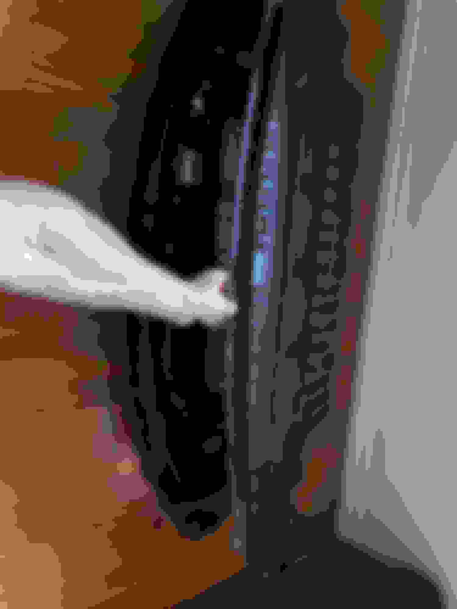
All the mounting holes are the same , same exact dimensions than the gtc/gts front under cover.I am trying to Identify the 12v Power wire in order to "operate" the active aero , please look at the pictures
- the two brown and red wires are the 12v power wires..? ( so the active aero goes up and down)
- the black wires are the ground..?
- blue wire ... in cabin " aero" switch.,?
- no clue about the other wires ( might be related to speed sensor since the active aero is supposed to goes up and down with certain speed, the same way the active rear wing works on the gt's models...
Please give your input regarding the wires color and their function ...
OK. My two cents on your wiring question. I dont believe the triggers are as simple as you are thinking. The decision to open the aero or not is all Computer driven. There isnt a simple speed sensor wire or anything like that. At least not that I am aware of. If the GTR computer has different code that isn’t in the GTS, then you may need to use an Arduino or something to control the splitter. That’s what I have to do with the rear wing project.
Even the cabin button for the rear auto wing goes through the computer first.
OK. My two cents on your wiring question. I dont believe the triggers are as simple as you are thinking. The decision to open the aero or not is all Computer driven. There isnt a simple speed sensor wire or anything like that. At least not that I am aware of. If the GTR computer has different code that isn�t in the GTS, then you may need to use an Arduino or something to control the splitter. That�s what I have to do with the rear wing project.
Even the cabin button for the rear auto wing goes through the computer first.
yes ideally, It seems I need the ecu for the front active aero coming out of the gtr though to make it work...
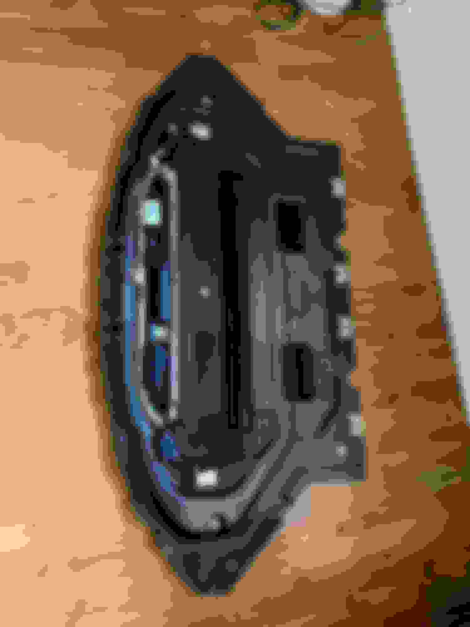
I am trying to find out which wires triggered the motor on the aero tray so I can active it manually...
If you are trying activate manually, here is what you need to do.
First, the activation is based on the motor polarity. The motor goes with positive on one side to open, and positive on the other side to close. That’s how the motor works. The issue is that you now need to deal with the limit switches (which i assume are some of the other wires.
So if you made a circuit, it needs to run polarity to the motor until the upper limit switch is activated. Then in reverse run opposite polarity to the motor until the lower limit switch is activated. This can be done with a microcontroller (Arduino) w/motor controller pretty easily, but the trigger is the interesting part. For instance, what do you use to trigger. A switch is really simple. Tapping into the rear aero is a little harder. The motor wires only see voltage during movement. Once the limit switch is hit, the computer shuts of voltage to the motor completely. So finding the right method to trigger is a challenge (solvable tho)
Do you see little limit switches in the mechanism? All the above is based on my knowledge of the rear aero. Happy to chat on the phone if needed.
Please keep in mind I am not an Arduino or circuit genius, which is why my project isnt complete.
Got it thanks for your input,
what do you think about those unit to control the aero tray?
That is a fantastic job! I have a question that you may be able to answer...how easy is it to replace the red circled rubber piece in the attached picture?
That is a fantastic job! I have a question that you may be able to answer...how easy is it to replace the red circled rubber piece in the attached picture?
It is pretty easy to replace this part , 12 push retainer clips to remove ...
That is a fantastic job! I have a question that you may be able to answer...how easy is it to replace the red circled rubber piece in the attached picture?
Reviving an old thread on that rubber piece. Anyone with that piece torn, scuffed? I presume the rubber is to protect the actual aero.
Mercedes SLR McLaren 722 S Is Extremely Rare Example Modified by McLaren
Slideshow: A one-of-one U.S.-spec Mercedes-Benz SLR McLaren Roadster became even rarer after a factory-backed transformation at McLaren's headquarters.