When you click on links to various merchants on this site and make a purchase, this can result in this site earning a commission. Affiliate programs and affiliations include, but are not limited to, the eBay Partner Network.
So my turbo actuator started acting up again, which required a repeat of the repair I did last time. I took a few more pics this time though, so as to help others.
Engine:
OM642
3.0L V6 Diesel
Symptoms:
1. Poor acceleration
2. Very little power at highway speed
3. May or may not be temporarily fixed when restarting the engine
4. May or may not have a CEL
DTC's
2359-002
2510-001
2136-002
and others related to boost pressure.
Solution:
remove and repair the turbo actuator
cost diy:
about 10 cents worth of flux-core silver solder.
Cost at the dealer:
about $3,000
pics to follow
Last edited by marc hanna; May 21, 2017 at 03:06 PM.
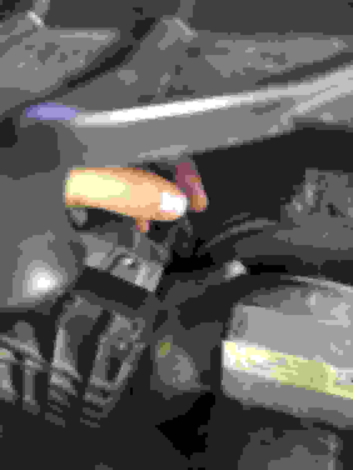
Here is the motor with the engine cover removed. If you have an R class like I do, you have to remove the cross member also.
1. This is the turbo actuator
To get at it you have to remove the Y-pipe for the intake and the heat shield on the turbo.
The he best way to remove the Y-pipe is to loosen off the 4 e-torx screws (numbers 2 through 5) and then the gear clamps (6 and 7 + another right in front of the turbo) and then pull both air boxes towards the sides. The Y-pipe will come out pretty easily then.
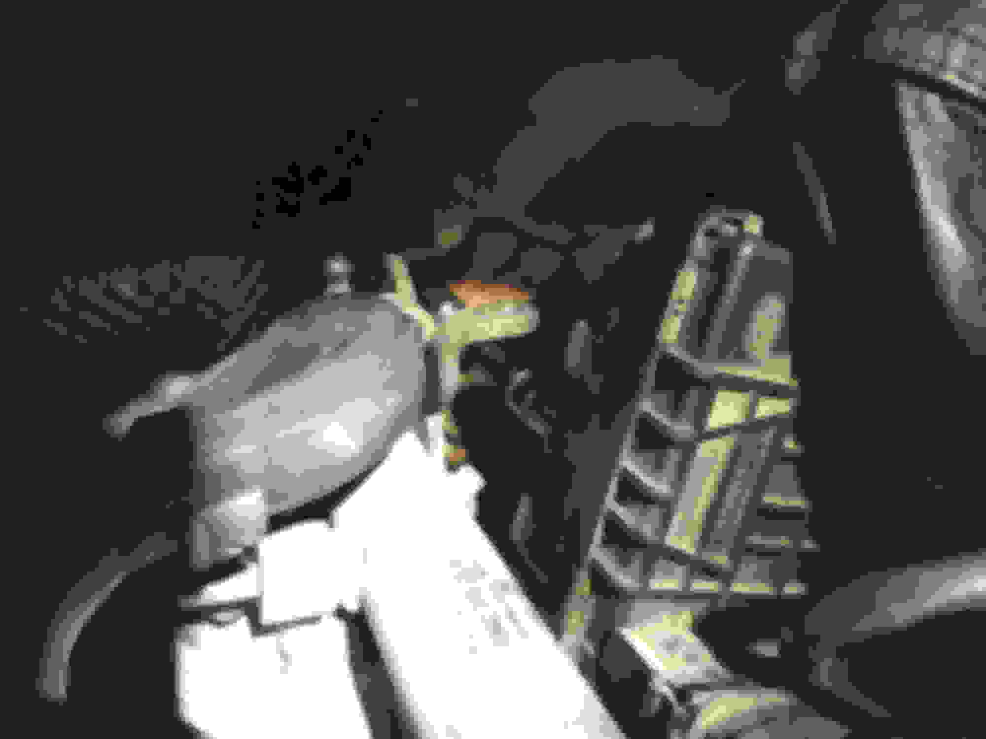
Here, you can see the heat shield (1). If you don't remove this you can't get at the mounting bolts for the actuator or the linkage. You will need to work with a cold engine here because you will have to rest your hands on the turbo while working.
The shield is held on with three e-torx bolts (2, 3 and 4). Depending on the shape of your engine bay it can be a little tricky trying to get the heat shield out.
At location 5 you can see the electrical connector for the turbo actuator. You will likely have to get the actuator unbolted before you can disconnect this.
Last edited by marc hanna; May 21, 2017 at 02:53 PM.
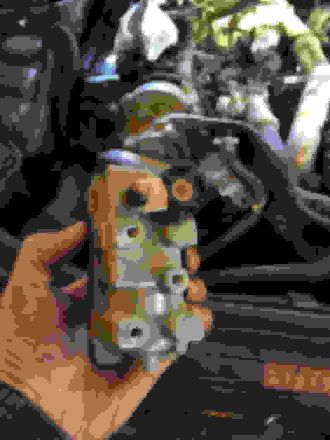
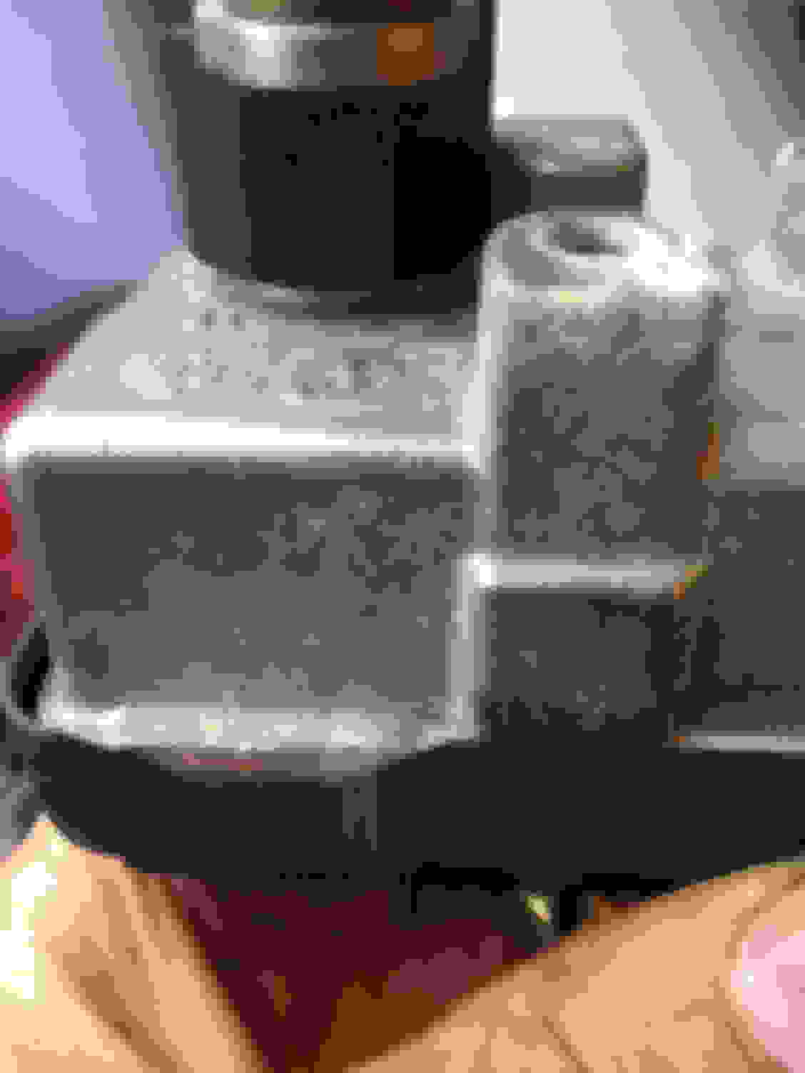
Here is the back view of the turbo actuator and mounting bracket (thanks iPhone camera).
Item 1 is the linkage arm and 2 is the swivel joint connecting to the actuator arm. 6 is the actuator arm.
To remove the actuator you have to unbolt numbers 3, 4 and 5. To get a socket on bolt 3 you have to disconnect the linkage. It is held together with a fancy E-clip. I used a stubby flat head screwdriver to get the E-clip off. Do not drop it!!!
This is a really tight space, but with a 1/4" drive ratchet and socket you will have enough room.
After cracking the bolts I used a combination of extensions to spin out the bolts. This is done blind with one hand. If you have magnetic tools, this would be an asset. I however do not, and therefore I was very careful to contain the bolts in the socket as a removed them.
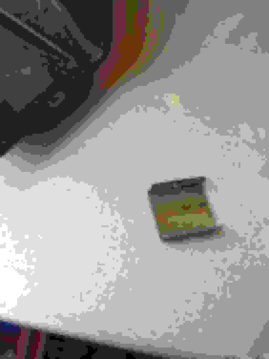
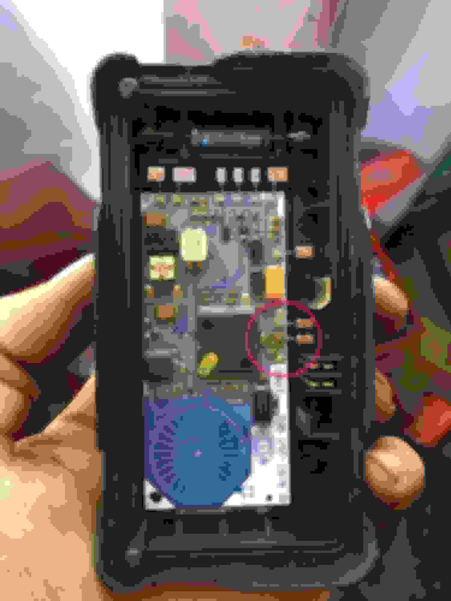
In my case this was the problem area. A lead had broken free - the same one as last time. The solution was to re-solder it. There are also a few rebuild services out there in case your solution isn't as simple as mine. I suspect that there is a little too much current going through these tiny wires, and therefore if I ever have to do thus again, I'll cut out the wire and solder a heavier gage one in.
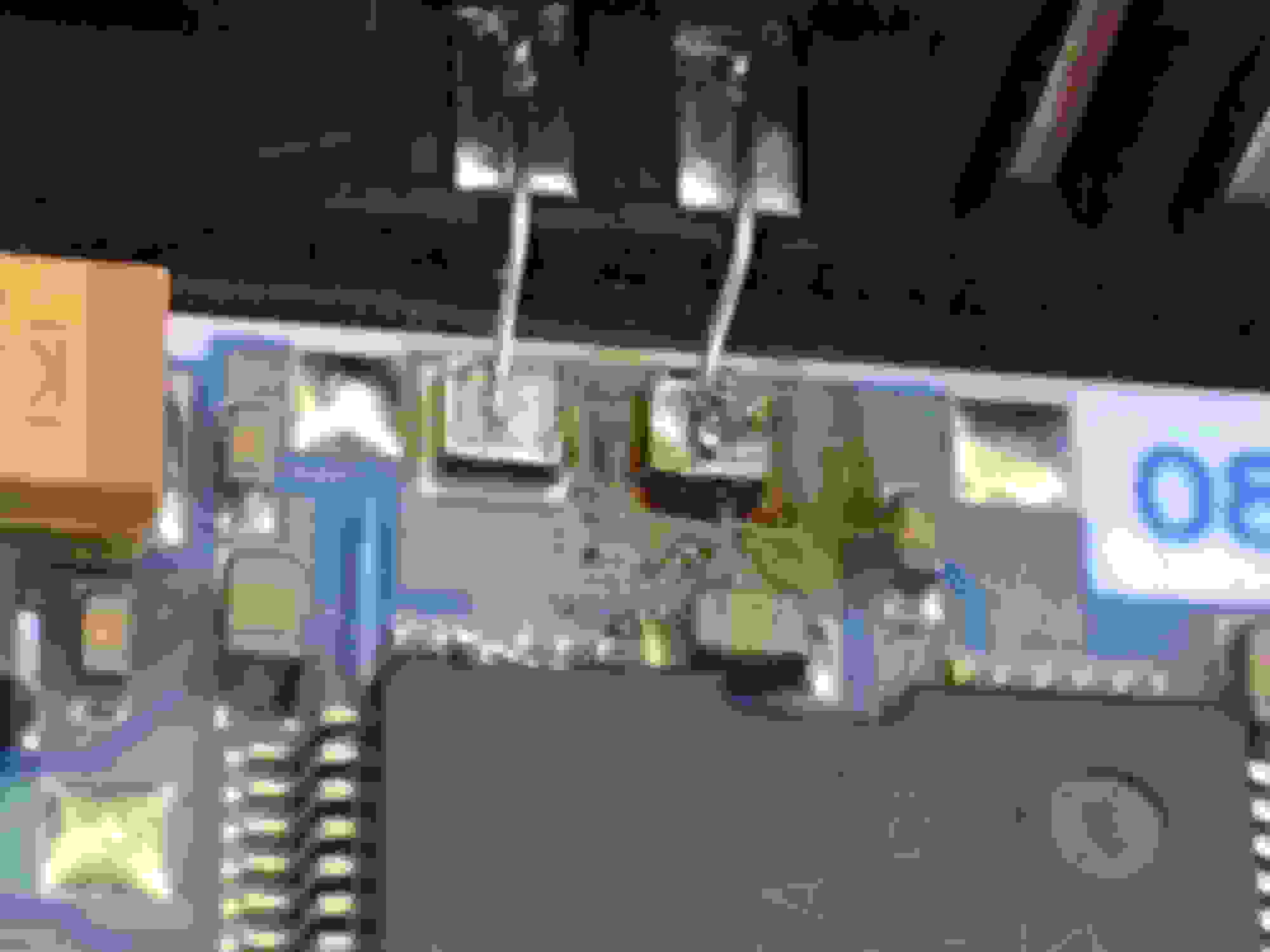
The cover pries off quite easily. There are no wires that you have to worry about. The two halves connect electrically by the spade connectors to the bottom right of the circle. Here it is re-soldered with an extra glob of solder to make sure it's solid.
the flux-core solder makes a little bit off a mess which I subsequently cleaned up with a q-tip and some alcohol.
Last, just reassemble everything in reverse order. You should be able to clear out the fault codes now. I use an icarsoft i980 scanner for this. Prior to the repair you will not be able to clear the codes.
My research has found that these Hella actuators are used in a lot of different makes and models - German, Japanese, and North American cars. So this problem might be more widespread than people realize. You cannot buy these actuators as a stand-alone device.
So if you know anyone that is having a problem with their VGT (variable geometry turbo), this repair should be considered before the dealer's recommendation of a complete turbo replacement.
Last edited by marc hanna; May 21, 2017 at 03:59 PM.
Many, many thanks to Marc Hanna for this post! Recently had a P0234 code and decreased power on my wife's 2008 ML320 CDI. Opened the hood and could see that the turbo actuator wasn't moving. Subsequently found the exact same broken solder connection as in this post, and the one next to it seemed close to breaking (would flex/bend when pressed with a toothpick). Resoldered them both and all is good again!
However, I found the resoldering was a real challenge. I have moderate experience of working on printed circuit boards (PCBs), but not a huge amount - so maybe I was doing something wrong? I initially attempted to apply liquid flux, then heat the connections with my soldering iron and add some tin/lead electronics solder. However, the solder would only stick to the soldering iron - it formed little ***** of solder on the iron and would not stay on the joint itself. I found some other descriptions of turbo actuator resoldering, and some other postings stated that the wires and pads were stainless steel, and thus required the use of silver solder, and silver flux. I then noticed that Marc Hanna specifically stated to use silver solder in this post. So I purchased some silver flux, and flux core silver solder, but I was still having basically the same problem with the solder not sticking to the joint. After a couple of attempts I began to see copper at the pads. It seemed as if the silver flux had taken off some sort of plating (stainless steel? chrome?) that had been on the top of the pads, and left the copper exposed. I scraped at both pads with a tiny screwdriver until I got some nice copper exposed (while doing this the jumper wires snapped off, but not a big deal: I subsequently used a small bit of 26 g jumper wire to replace the original connection wire). Since I now appeared to dealing with regular copper pads (such as I have experience with on PCBs), I reverted to my usual liquid flux and tin/lead electronic solder. I applied flux followed by a dab of solder to each pad, and then added in the 26 g jumper wire, and achieved success.
If anybody has a lot of knowledge/experience about this, I would love to hear what they think. Is it a common practice to coat copper pads with stainless or chrome or something? PCBs are covered in the green coating that is easily scraped off, so is this a different version of what is done on PCBs? If so, is this done for anti-corrosion properties, I assume? If I come across this in the future, is there another technique that works other than stripping off the plating/coating to expose the copper? Or was my technique faulty - such as should I have used higher heat with the silver flux and silver solder?
Anyway, thanks again to Marc for this great posting.
60/40 rosin core works very well in pace of silver solder. Silver solder ends up looking gold in appearance and is often used instead of TIG/MIG welding on parts which need to have some flex and get hot, but not over 900F hot. Just an FYI, the stock solder looks closer to 60/40 than silver solder. Killing off your EGR will prevent 95% of this sort of failure as “coking” of the turbine hot side is drastically reduced and vanes are left free to move without requiring large amounts of heat production amperage to this circuit. That said..indeed, thank for the look inside.
For those swapping to non OEM application Garrett turbos does anyone know if the board logic is the same between a Ford, Ferrari, Benz or Porsche? Does anyone make a stand alone VGT/VNT controller for applications which never came with Variable Geometry? I only ask because I want to eventually use one of those ten bladed screaming 03/04 Ford 6.0 Garrett 3782VA turbos on a gasoline project car just for the sound and stupid fast spool, not necessarily the peak potential airflow.
This is a great story, but how do you test it out after you are done so you can be sure that your solder job did not destroy the circuit? Is there anyway to apply voltage and make it move, and then verify the position sensor output?
I'm sure there is a way, but I just try to be careful not to bugger anything up. The only thing I test before reassembling is the conductivity across the solder joint. Other than that, I don't know if it will work until fire-up the engine. So far, it's been good both times.
It actually failed a third time, so this time a just replaced the actuator with a rebuilt one.
Tips for soldering:
1. sand or grind down the surface prior to soldering
2. apply a tiny bit of flux or use flux-core solder
3. make sure your soldering iron tip is super clean - clean it up with a little sandpaper and a damp sponge - this sometimes needs to be done during the soldering job
4. heat the joint and apply the solder to the joint - don't apply the solder to the tip of the iron
I'm glad people are getting some benefit from this relatively simple and cheap repair.
Hallo everybody.
Thank you for this great article. Im facing now the same issue with the actuator. Sometimes lacking of power the car is jerky when put down the throttle pedal. My dad is an great electrician and he helped me resolderimg the parts. I sanded the contacts bot with a dremmel that the cooper layer appeared.
But I have question what could cause this damage? Isnt that only side effect of anotjer issue? My car os now 277k km cca 10k km back was my turbo refurbished as well as the mechanical parts in the actuator but the PCB not.
I will post later photo od the resoldered actuator. Tomorrow my dady will resolder the second contact as two weeks ago only one contact was loose.
You did a much nicer job than I did. I think that generally, these conductors act as fusal links. My understanding from a rebuilder of these, is that the problem originates in the servo mounted on the other side of the board. If the servo has too much mechanical resistance, it will draw more current. If it ends up drawing too much current (combined with it's physical proximity to the turbo and the associated heat) the conductor gets cooked.
Me not it was done by my dad but thank you. I was thinking to put some grease or vaseline on the gear wheels and on the worm wheel. But the waseline I have is only up to 125 celsius degrees so I have worries if it will not melt in the heats which are in the engine bay. U putted some silicone spray on the gears to at least grease them a bit. My gear wheels were swapped last summer for new ones.
or do you think that the servo resistance could be that the mechanism that operates the variable flaps in turbo could have a problem or it is stuck and could make a resistance for the servo in the actuator?
Last edited by MacSixx69; Mar 13, 2019 at 05:26 AM.
so after the repair and no problem today again limp mode. 4times one by one. No CEL. Tomorrow I will go on the star to mercedes dealer to see whats wrong again. I think its the actuator I will dissassemble it and let you know.
Mercedes SLR McLaren 722 S Is Extremely Rare Example Modified by McLaren
Slideshow: A one-of-one U.S.-spec Mercedes-Benz SLR McLaren Roadster became even rarer after a factory-backed transformation at McLaren's headquarters.


 but thank you. I was thinking to put some grease or vaseline on the gear wheels and on the worm wheel. But the waseline I have is only up to 125 celsius degrees so I have worries if it will not melt in the heats which are in the engine bay. U putted some silicone spray on the gears to at least grease them a bit. My gear wheels were swapped last summer for new ones.


