When you click on links to various merchants on this site and make a purchase, this can result in this site earning a commission. Affiliate programs and affiliations include, but are not limited to, the eBay Partner Network.
Well, I thought I took a wide shot of F32 opened up. I was so busy with cleaning up the molten mess, I buttoned it up without a second thought 🤦🏼♂️. However, mine looks identical to your vid pic; fuse rating/placement, terminal studs, and both relays.
I also performed my own �bench test� with the alternator. After checking all 12 diodes (because lights were flickering only when engine running) I decided to set my cordless drill with a T50 into the armature shaft and run at 1800 RPM. It only produces 0.534VDC raw and surprisingly 0.872 - 3.410VAC. Seems the alternating current is a byproduct even with good biased diodes.
So to answer your other questions.
A1) The white stain is actually discoloration of the tinning from the molten plastic. It came off easily with some light 150 grit action.
A2) Yes, that stained face is the bottom of that bus bar. I had removed all the nuts and pulled all the components out to give them a thorough cleaning.
B1) The link of V19 that was overheated, terminates to the B1 stud. It is the short cable that connects to the positive battery clamp, and the bus bar (with the stained face) is the �jumper post� that protrudes out of the top of F32, which is underneath the V19 leg.
There may be a good possibility of a loose factory connection, as this was my grandmother�s car and she only took it to the local dealership. Both batteries have been changed twice each, with zero regard as to what the root cause is. Painful to think about those service techs wearing blinders and only obeying what the work order sheet says is wrong 😑 �Bad batteries�swap them out and move on to the next car�. Adding more waste and unnecessary expense.
Ok, I won�t go on ranting, lol.
The nylon insert in the hold down nut was hardened, as well. I was leery about putting F32 back in service, but I thought �might as well try it and see� 🤷🏼♂️
I have a few pics that may help you determine the differences in our cars W212 v X204. Cheers!
The toasty V19 solid state relay and crispy plastic surrounding the post are the consequence of regularly pushing 80+Amp into the deeply discharged main battery.
This electrical abuse is dished out by the alternator when it switches back from crazy to normal operations.
By the above I mean the origin is not the loose relay post, that is a consequence of 80+Amps spikes.
It is clearly a good move to fix and keep an eye on these connections :
ALT > V19 > Hyundai > AGM .... HOT!
Ultimately limiting the discharge voltage, limits the charge current within range. Seeing 12.6v is a perfectly good neutral float voltage.
Last edited by CaliBenzDriver; 11-07-2021 at 03:50 AM.
Agree Cali.....Actually that B1 post/terminal ( lets call it B1-Input) which overheated, if it weren't for eco algo of the alternator itself would not see high amps while engine is running.
The wiring or bus bar arrangement of F32 is as such, MR8 which is the alternator output to F32 if serving car electrical needs, serves the demand within the bus bar of F32 and not via the battery and hence B1-Input is low amperage load. This is only true when alternator voltage is at least 1.5 to 2 volt above battery voltage aka not while in dumb-azz discharge mode and also not while in insane-high-charge rate.
SIDE NOTE :
Cali, after the ECO feature I killed , the crazy charge-discharge cycle still stay the same. So it is part of the ECM strategy managing the alternator, regardless our car has ECO start stop or not. My friend has a 2012 C200 and he has no ECO start stop and I got the chance to play around with his alternator charging profile, it is bad, at idle its under 12.6V alternator output and will only hit 13.8 -14.x volts if aircond at full blast ( while idling ). His battery is a 2 years affair... LOL.
This Jakarta-Bali trip, alternator LIN I disconnected, I like it ....charging is so polite and civilized.
The so called dynamic idle control of ECO start stop is actually not completely loss with me killing ECO start stop feature, as I initially thought....but it is engine coolant temperature dependent. For reason I do not know, when coolant temp exceed 90C* ( *must use OBD2 to see due to the "manipulated" coolant temp reading at gauge ) , the beautiful low idle of 550ish RPM is not executed by the ECM, it will be close to 700 RPM. Only when coolant is 85C there about, then the low idle 500ish RPM can happen.
The only time I see sudden battery discharge ( with alternator LIN disconnected), is when electric power steering in action.
The sudden demand spike is not having long enough duration to get alternator to response.
Within the 10 hours of driving, it is so nice to see amperage NET into battery being so low, even under 1 amp sometime and voltage
near steady 14.1V as max
Surya, I am so glad you had great voltage control to enjoy your long roadtrip.
The minimal battery charge current means your alternator was always supplying the whole electric loads and the battery was transparent, the way we like it to be.
TRIP EXPERIENCE:
Did you notice if your engine was running smoother with more torque -Or did the stable voltage not enough to transform your M276-TT without module enhancements?
It is interesting to note your finding about the deep discharge yoyo not at all linked to ECO feature active or frozen.
Last edited by CaliBenzDriver; 11-07-2021 at 07:25 PM.
I don't feel any performance change from the better charging.
To protect my battery from the crazy ECO charging algo the ECM has, I charged (top up ) my battery twice per week in Jakarta and those are short run use case, all under 1 hour drive. So I can't compare them to now disconnected LIN and 10 hour run.
BTW, I have replaced my main battery before the trip. It is 3 years 3 months old already and is reduced for its CCA.
I can push its use another year with ease, but I made that battery as my emergency generator back-up battery.
ALTERNATOR VOLTAGE DATA, sorry no amperage data
Here is attached log and summary/graph of the last +-1.5 hours Jakarta to Batu City (+-10 hour) run.
Last fuel stop to a resto. 5,159 data points at 1Hz, or 85.98 minutes.
The exact route is : S7.378474, E112.54542 to S7�54'12.3"S 112�33'46.5"E on google map.
I tried pasting a link but MB Forum somehow removed part of the data and link can't work.
Start of trip, long idle waiting for my fried to arrive.
See the idle is still low, within 600 RPM.
=========================NEXT===============
Arrival, cooler ambient temp at 25C.
I was cooling down the turbo. I did not do crazy speed or was a maniac, I was decent.
The so called thermal management of this ECM is an opportunist bastarzd... when it sees 25C ambient temperature from what was normally a 30C or more,
it will push my coolant temp to as close as possible to 105-110C ... in the name of better combustion efficiency.
4,519 data points at 1Hz, or 75.3 minutes of this trip to the cooler Kintamani region.
Take a closer look at the red line I drawn. When ambient temp goes down, ECU took advantage and start playing/increase with my coolant temp.
The drive gradient is not severe in anyway, so it was not from engine load.
I don't understand the logic here, save a bit from better thermal efficiency by pushing 105 - 110C coolant temperature, but at the cost of raising idling speed to 750 RPM which burn more fuel. Weirdo green junkie engineers... LOL.
ARRIVAL : 2 minutes before engine kill. Same 1 Hz data resolution.
See, 750 RPM idling if coolant temp is higher than 90C. As I said : Weirdo green junkie engineers
Ambient temp seems to increase when car stop zero speed is normal.
It is the air wash/turbulence from the cooling fan to the ambient temp sensor.
CHARGING - 4,519 data points at 1Hz, or 75.3 minutes of this trip to the cooler Kintamani region.
The B-BUS voltage dip in the beginning is all electric power steering heavy work. Plenty of tight corners and U-turn etc etc.
The 2nd biggest power sucker in a F32 Prefuse and of an unpredictable demand, is the electric power steering ....60 amps is normal for it.
Cooling fan is next 1st class biggest power sucker if at 100% duty, but it is kinda constant and if any increase, it does it slowly .
ECU works harder here, its a rural road, stop-go-slow-fast-yada-yada so more engine management duty compared to constant highway run.
Noisy ECU Pwr
Surya, the above graph is showing 250mV of noise and 1V spike as ECU power. Improving that can only make operations more stable... We know CAN transfers are in part immune to some noise but compounded with other factors like painted GND I can see getting ourselves... a yoyo!
The voltage is dropped somewhere with a less than perfect resistance ie. somewhat bad connection or inline.
Electrical noise is a foe that helps many issues develop. Resistive connection create a vicious cycle with heat and drop voltage! Toasty battery relay being a prime example of that.
ALT vs BATT: A TIPPED SCALE:
V19 batt relay is in it for something but it is not the main cause of ECU voltage drop.
ALT should always have the lowest impedance to supply circuit instead of BATT using its reserves. Meaning V19 is welcomed to have some amount of voltage drop to upset parity.
Can we identify this drop and fix it? Where is that particular drop from: Prefuse B1_Post, ECU Harness, ECU PCBoard, GND posts, ... I dono?
PreFuse out on the bench:
In the sprit of considering the obvious 1st, I am going to get intimate with my prefuse in the near future! Hopefully I won't be greated with toasted goodies just yet.
I will be concentrating particularly on all the heavy lifters: B1_post, V19 and K2... I know for fact they have had the sustained 80Amp already...
I am diagnosing this issue knowing these cars are so well engineered they all develop the exact same problems from the same causes. I am curious to see what stage my prefuse is now at and coat my junctions.
Any recommendations to fix the 350+Amp connections? Is there an anti-oxydant that can handle 150�C/300�F heat?
As an improvements, resistance needs to stay reliably super low under high currents. Else junctions get oxidized and heat up like a toaster. high currents F32 distribution
Last edited by CaliBenzDriver; 11-08-2021 at 03:22 PM.
I need to add below for your attention :
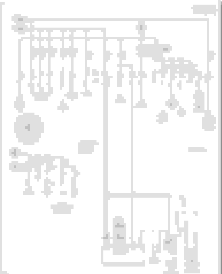
Becareful with the wiring diagram you are using, I believe it has significant errors.
I am assuming your car being a 2013 and having that Q-Diode is an ECO start stop version, and is very similar to mine.
If my guess is correct, you can verify it by visually looking at the pyrofuse on the positive battery terminal.
Is your wiring diagram from ALLDATA ? MitchelllDIY has errors too, big time around the F32 prefuse region towards the main battery.
In your diagram , it is drawn as such pyrofuse serves the F32 main power feed, NOPE it does not.
Pyrofuse on my car and I believed yours too, only serves the starter motor , nothing else.
Below is surely is a drawing error but unfortunately it is a dangerous one if someone actually follows that wiring for installation.
The alternator positive feed for F32 at MR8 is a dedicated wire, no sharing with starter motor.
MR8 fuse is not to protect the alternator, it is to protect the main battery from exploding if the diodes set in the alternator goes freeflow.
The connection I removed/crossed with black pen, that link between starter and alternator IF anyone actually install or add that interconnect, MR8 fuse won't work.
Alternator then has unfused connection to battery positive directly.
In the old days some engine interconnect alternator positive to starter positive, to save cable.
The pyrofuse itself is still a fuse mechanically and will blow on its own if ever a big short occurred. I believe it is 350 amps rated.
Cali,
When I was messing with my F32, I re-checked every connection for tightness.
All was good.
Don't worry about the B1-Input connector stud overloaded/overheat, if indeed it is tight..... it should be good.
It does not handle higher amperage than what the battery can take as charging amperage (engine running ).
The car electrical load when engine running is handled mainly by the alternator within the bus bar which is before B1 stud.
So B1 connector will handle surplus or deficit amperage only to and from the battery and not purely car operational amperage.
That ECU 1V voltage down spike and the 250mv yoyo as you indicated it seems a given condition.
As you know my ground has been beefed up so well and it helps a bit by 0.2 volt, however ECU cables size is something I can't change.
If I keep this car long enough and one day decides to replace the wiring harness to ECU, I may custom re-do the wires with size upgrade.
When using the Xentry, without engine running and ignition in position 2 ( ready to crank), and I let consumption stabilized it is 14 amps required.
I believe at least 10 amps of it is for the ECU alone.
If engine is running, easy 30amps for the ECU, but the power feed are 5 different fuses.
The logic side of the ECU I believed is powered by fuse 27 and 25. However I do not know which of this 2 circuits is the ECU voltage report coming from.
Below is a load test I did for my main battery, at 12.4 amps load ( halogen 50W x 3 ) and wire of 2.5 mm2 size ( 14 AWG) of about 2ish meters.
In theory of ohms law, 0.512 volt would be the voltage drop at cable end at the halogen lights, but that is assuming perfect copper cable only at 20C and without connectors yada yada.
Reality shows 0.751V drop. Halogen is an easy resistive load. https://www.rapidtables.com/calc/wir...alculator.html
Our ECU get the cruel kind of load, the inductive ones.
- Injectors
- Ignition coils
- Cam phasers
- Whatever other solenoids or electromagnetic coil based device
Also we have 2 Kings of Electrical Noise :
- Ignition coils
- Injectors
As for logic circuits or microprocessor components inside the ECU, I think they are 3 and 5 volts devices, so a good voltage regulator should
be able to handle up to engine cranking voltage drop. I don't think now I want to worry so much about 1V voltage drop spike down , looking at typical CPU used by Bosch.
The TC1766 has several power supply lines for different voltage classes:
� 1.5 V: Core logic, oscillator and A/D converter supply
� 3.3 V: I/O ports, Flash memories, oscillator, and A/D converter supply with reference voltages
From INFINEON CPU, Bosch ECU MED17.x uses this too.
I agree with you Cali, noise effecting CAN bus is probably the most worry in the long run.
My friend who works at MTU Asia Pacific once told me a story of how a ship PABX phone system somehow causing interference
and shut down his engine during a sea-trial. Marine wiring used by MTU is first class, yet that shi-et happened ..LOL
Thank you very kindly Surya for pointing out that B1 is not the junction where ALT is landing and that it's only the battery path.
You're entirely right also about the misleading diagrams. They're made for armchair mechanics... nothing trumps good hands-on tracing!!!
Specifically the ALT does not land on the starter contactor to go meet with main battery.
While hunting down chaos, I am still seriously interested in figuring what in the path of power supply (ALT/BATT) is introducing a sizeable drop voltage resistance to glitch ECU, (PreSafe, LimpMode,...) F-SAM, etc.
It is a shared junction up front in engine bay: ALT, PreFuse ?
I've seen 10.x VDC data read out for "brake Sw" that may be related - Let me dig more specifics.
VDC & Noise... SNR:
What impacts CAN transfers is the combination of noise and low voltage when they both get invited in.
- To help solve this we can improve both prongs: less voltage drop and less noise generation/radiation.
- The Signal Noise Ratio gets stacked against us when greater noise and lower voltage are present.
It sure does not help to shut-off ALT during accelerations on already low voltage and high drop circuits: WOT LimpMode!
Last edited by CaliBenzDriver; 11-10-2021 at 01:25 AM.
As curious as you are, so am I
I shall re-visit the trip to Kintamani region, ECU voltage wise.
0 to 476 data point. Start of trip, departure from my place. Lots of electric power steering ( EPS ) use. 90 degrees corner a lot and 1 U-Turn.
When EPS in use, B-Bus Voltage which is not ECU, lets call it overall car voltage excluding ECU......... will spike down accordingly and since the power demand is up to 60 amps if for a maximum
steering turn, ECU voltage dips down along.... no way to avoid it.
Lets take a closer zoomed look at the 476 data points I speak of :
Now for the interesting part. 3,460 data points to 3,642
What makes ECU voltage dips down , other than spike demand of EPS ? Let's zoomed in 3,460 to 3,642 data points.
Well, we got that answer today. It seems slowing down to zero speed or near zero speed, makes ECU busy and uses more power than while at constant moving at speed.
Observe ECU voltage dip down at 12th data points and when car is slowing down fast to 10 KM/H, since no EPS involved here, B-Bus voltage never spike down like when at 85th data point.
I guess when car suddenly slows down to very slow speed or stop ( maybe with brake hold too ) ECU has to choose different mapping, and sending out more instructions aka electrical commands to cam phasers, and the rest of the ECU hardware team and Transmission Computer team....bla bla bla = MORE WORK.
To confirm this, there is no other way but to sense current consumptions at Fuse 22, 23,24,25 and 27 at all once ( with special fuse adapters) or separately but at the same time...
I think because a 1 Hz resolution graph is available and with decent 1/100 volt resolution, we start to see what could never be seen from simply watching the engineering mode voltage reading at instrument cluster.
Now, my hypothesis to your question Cali .... Cali wrote :
While hunting down chaos, I am still seriously interested in figuring what in the path of power supply (ALT/BATT) is introducing a sizeable drop voltage resistance to glitch ECU, (PreSafe, LimpMode,...) F-SAM, etc.
It is a shared junction up front in engine bay: ALT, PreFuse ?
We are seeing localized voltage drop. It is quite common actually, if one can log it at, at least 1Hz... the faster the better.
Imagine this : an ECO start stop car and with proven ECO-Weirdo alternator charging algo from ECM via LIN and while having a battery already aging, with reduced reserved capacity and surely reduced CCA and car has Electric Power Steering and lots of heaters option ( cold country car ).
Adding another layer of misery : the car electrical connection integrity is not so good. Lots of winter salt yada yada.
I think given the right circumstances a car I described above can have intermittent electrical issues which goes* away ( *for certain period of time ) simply by replacing the main and AUX battery.
Mercedes sold us a unique kind of electro-gasoline car
Kidding aside, our W212 , especially gasoline version, needs one to really take care of the car's electrical hardware.
Smart top up charger and good periodical battery replacement is our MB best friend.
========= FOR FUTURE TROUBLESHOOTERS landing on this post =======================
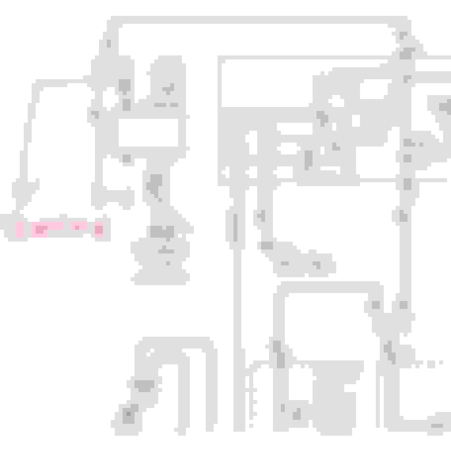
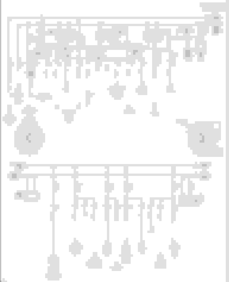
If one really fear loose connections as what Riles experienced, red circles below are possibilities where it could happen.
I only circled the most upstream ones and is considered MAIN BUS BAR territory.
Cyan color is electrical flow direction ( highest voltage to lower voltage ) when alternator is running.
Green is like a secondary circuit which needs either V19 Q-Diode* ( *solid state relay while being a diode too) or a true mechanical relay like K2 to be in closed contact to deliver power to the devices downstream.
In the case of main battery, a V19 Q-Diode failure of its non-diode section contact ,will not allow main battery to get charged because the diode section will block the current flow.
But alternator can power the car electrical needs.
Easy to test, while engine running. Ground stud or battery negative to IM1 terminal, its voltage is the same as ground to the jumper positive post if V19 Q-Diode non-diode section contact is healthy.
Other Loose connection :
Red circle below is when AUX baby battery 12Ah at the trunk does not seems to charge or power maintain the car well ( assumed healthy battery ) during an engine SLEEP of ECO Start STOP.
K114 relay at AUX battery could also be the culprit, but we are discussing F32 prefuse here.
Other possible loose connection is obvious, any bolts + nuts can be loose...
If you want to verify K2 relay contact point health, with engine running turn on at least the headlights and verify almost the same voltage
of its easiest to test output, the IG1 compared to jumper positive. IG1 is for rear SAM and headlights are powered by rear SAM ( at least for my car ).
I think we are staring at a good opportunity to retire many Benz issues in one shot. We are working way up with the power distribution. Given a chance, issues at that level can snowball down the line. (Eg: the Pbx bringing down a large ship engine)
- I am not going to map car troubles to power issues. Instead I am going to fix this and whatch what issues disappeared!
Start vs. Run preFuse power:
The whole car electrical distribution circuit is built with a couple short falls that can bite at different stages.
During start, ALT is out and V19 SSR has to feeds all car electricals. It drops about 400mv, fine with a good battery during crank but not so below 10volts.
Stackin' up: compounded drops
The ECU Power graph exhibits a mix of ripples. The large downwards voltage swings are attributed to the 60Amp ESR. The small riples are assimilable to noise without distinct pattern. It could be FuelPump, EngineFan, BlowerFan.
The interesting part is realizing the steering rack can steal available power from the ECU supply. To me that is evidence the main fuse connections are dropping significantly. We can't make the fuse transparent but we can improve its connections to lower parasitic drop.
Stacked fuses:
The ALT feeds preFuse branches fuse through a main 350A + branch fuses. Each branch adds to the total equivalent resistance. More fuses, more connections... additional drop.
Individual signatures:
Each fuse has a combnation of attributes (Amp rating, amp load, serial resistance) that may be interesting to identify branches by looking at its load signal.
> Remote regulation!
- In order to dynamically offset the drop voltage from the largest fuse, the alternator is externally controlled with data remotely measured. The goal is to minimize voltage swings.
The Smokin' Gun:
low Amp fuse melted by hoverheated bus!
You can observe the difference in color of the distribution bus nuts... you know this piece had to get hot! Did you noticed the internal nuts have no plastic inserts stopper like the professional-looking external nuts...
What made the bus hot are the 7x oxidized connections (surface + nut) and the V19 handling the crazy charge/discharge battery currents.
Right next to hard working V19 the bus serves a branch of smaller fuses which output is not bolted on.
The color of the two nuts on the main 350A fuse looks better than the smaller ones with way less current.) Are the main nuts stainless steel ??
By the time you want to strap a thermocouple to the bus bar out of curiosity... you might as well fix the problems all together and be done - The bar would make very informative thermal pics👍
Prefuse R'nR Enhancements:
Rework the parasitic drops so they don't create additional problems
1- Corroded contact surfaces > Silicone/Zinc
2- Loose heated nuts > Loctite
3- 50� upgrade nuts to Stainless like main
Bus NUTS:
When comparing the contact surface to the nut thread, I'd rather use loctite on the nut than a lubricant that will help it vibrate loose with heat.
Deoxing -> Acetone -> Loctite!
Last edited by CaliBenzDriver; 11-11-2021 at 11:46 AM.
Fuse is both good and bad.
It does protect , yes but it is not free lunch.
Fuse burnt-out metal part or the burn-link is on purpose thin, suitable to its rating.
Those small thin small surface area alloy, that burn-link produce not only heat, but also extra resistance.
Being small , it is like we inserting a small cable in a circuit, therefore ampacity limits hit the weakest link. Yes I know it is super short metal strip.
During my battery reserve capacity test ... post no 185, I got extra 0.239 Volt loss , reality vs calculated.
ABOVE : See the ATO fuses for positive and negative wires, far right bottom of photo. At 12.4 amps load, which is not big, those fuses I shot with my thermal imager, showed like +12C to +15C or so temperature increase over ambient. The WAGO connectors are fine, the cables are fine and the alligator clip at battery terminals are fine. It is only the ATO fuse itself being so hot and surely its two legs. It is way hotter than a typical home use MCB of say 20 amps rating under the same 12.x amps load. +5 to +7C is about the max temperature rise I observed if an MCB.
The F32 bus bar, the area I marked red below, that is an odd design, thinning the bus bar there for the fuse is a big question for me,
WT-Hell for ? That will add heat. Maybe it is allowance for bending the bus bar when one tighten the nut of the fuses.
Relays like K2, or all relays in Front and Rear SAM, all are voltage dropper too.
Relay R at front SAM is HOT !!! 17-19C above ambient temperature.
Relay R, a 0.129V voltage drop too, for a 12.4 amps load. Relay contact points/dots are so small, for each activation its metal contact dots get eaten away bit by bit, it is given.
Below is a contact point from a 20Amp dual pole switch from Schneider called Kavacha, serving a 0.75Kw pump at 230V or only 3-ish amps running and expect 500% surge/inrush during a switching event. It is a pool pump. I got 2 of the same units pumps and switches. https://shop-sg.se.com/kavacha-20a-4...itch-ip66.html
The switch assembly probably came loose. The assy uses 4 screws , and hence spring pressure on the said copper bar with the contact point is not
pushing hard enough anymore if those 4 screws come loose and not compressing the components to sit/stay where they should. I retired this switch.
Poor contact pressure probably
Below, its twin sister switch, same duty and decent wear pattern from arching. This switch is still good. I am still using it but for a low power floodlight LED of 30 watts. The 2 pumps got new switches, 35 amps rated one this time.
The 2 above switches have already approx 1,300 - 1,800 switching cycles.
A relay would have the same fate as the ruined switch if old enough or the coil winding does not produce enough magnetic pull
to close the contact point well.
Well, that summarize most potentials maintenance items we need to pay attention to, aside from all connectors used here and there and those grounding points on the car metal.
Relay is actually the tricky ones as car's own mechanical vibration and bad road surface can create intermittent contact if them relays are not
in the best of health , plus the misery of engine bay heat for K2 and Front SAM's relays.
Some critical trouble codes does not need 1-2 seconds voltage drop/loss to be triggered.
I am waiting for a part 2 of Pine Hollow Auto Diagnostic video on a 2006 Acura.
In part 1, the technical manual indicated for Accelerator Pedal Position ( APP), 0.2 seconds duration of voltage drop/loss will issue the DTC and the limp home.
See Minute 7:40 seconds, from Part 1
the strange cutout pattern around branches is to insulate the heat locally while still allowing current distribution.
As we know heat causes metal to stretch so the bar itself is not flat to help it expand/contract at will without mechanical stress.
This design and the discoloration of branch nuts is evidence of heat generation by significant resistive drop.
Scaling factors: P = U x I
We know that we are dropping about 250mv with spike of 1V
Combine that with 150Amps and you can easily climb above 100W that need to be dissipated. The air tight enclosure helps heat accumulate.
We've seen the burned B1 post, the burned lower fuse and the discolored bolts - That's my call for action to eliminate parasitic drops. Fuses heat yes but nuts nop!
Do you know what torque value should be applied on the prefuse posts and fuse nuts, besides G'nT?
+++ (AC pump contactors
I've developed and built a fix for this problem on my 1.5Kw grey sump pump.
I use a single-phase soft-starter and a motor-rated contactor to switch at zero current. To trigger all that I use a level sensor with a stainless rod.
> Having eliminated the in-rush switching, I get zero wear.
+++ YT video by PineHollow troubleshooting:
Great video. This guy really is a fulltime genius.
He has reached the point where he's able to link the APP faults to crappy GND... small world!
I know enough about Acura and Benz design to say they share a Bosch parent.
I have little exposure to No1 Toyota but can see the new fancy Benz features are released on similar schedule. All these cars are German, not copy-cat, LICENSED!
Last edited by CaliBenzDriver; 11-11-2021 at 02:54 PM.
Reason: in-rush fix
Cali asked :
Do you know what torque value should be applied on the prefuse posts and fuse nuts, besides G'nT?
In WIS it has this data, I seen it before and battery posts too.
Our Prefuse daisy chained fuse connections seems like a ideal place to use DEOXIT or a deoxidizer plus film protector.
The only thing our prefuse design needs is great connections. Benz designed this to be sensitive to back-to-back dropped voltage.
I've never used the magic DEOXIT!
What has been your experience, what formula to use D5, 100%?
It seems to be be a silicone gel laced with zinc ions.
Has anyone used DeOxIt around his car electrical distribution?
.
Last edited by CaliBenzDriver; 11-12-2021 at 01:53 AM.
I've never used the magic DEOXIT!
What has been your experience, what formula to use D5, 100%?
It seems to be be a silicone gel laced with zinc ions.
Has anyone used DeOxIt around his car electrical distribution?
.
Since I don't have electrical corrosion issue on my W212, I hope those works as advertise.
I have a standalone DAC from Asus http://www.jimmyauw.com/2012/12/17/a...y-exploration/
It does need cleaning at the volume control and so are my JBL Studio Monitors.
You know those disgusting sound coming from a dirty potentiometer / volume control.
I intend to try my pair of Deoxit there and maybe also get the D5 version with propellant + contact cleaner too
After disassembly of my F32 panel, I gave each contact point a good cleaning with 180 grit and a film of dielectric grease. Then I wiped the contact points with a rag to disperse the grease better. I did notice that the metal used is tin plated copper and by using abrasive, I knocked down some of that plating. It wasn�t intentional at first, but then I figured I would do it on all the points and then coat everything with grease.
As for the fasteners, I did notice the studs are long enough to accommodate a nylock, although a castellated lock nut would be best. Using nylon as a locking material is fine, but at the temps the metal reached to blue the tinning and melt the surrounding plastic, it didn�t survive. I had to replace the nylock on my B1 connection point, because the nylon had melted off. And the exterior nuts are a low grade plated nylock, not stainless.
M6x1.0 316SS castellated lock nut
And yes, they are pricey, coming in at roughly $5 US each. Possibly a corner cut to save some costs.
there's the main battery, thats a standard AGM H6 aka Group 48 on gas/petrol cars, and a H8 aka group 49 on Diesel cars.
then there's two different sizes of aux batteries, some cars have a 12AH AGM it in the trunk, others have a even smaller one embedded in the dash under the instrument cluster.
he trunk battery for my 2016 E350 4matic wagon is A0009829308 or A0009829608. This is basically a largish motorcycle battery, except I have yet to find an aftermarket AGM motorcycle battery of the correct size that has the fitting for the overflow vent tube (even AGM batteries can leak under extreme conditions). I do not know the PN for this smaller battery, if you have a VIN that uses one, I can look it up.
 11-07-2021, 01:23 AM


")