When you click on links to various merchants on this site and make a purchase, this can result in this site earning a commission. Affiliate programs and affiliations include, but are not limited to, the eBay Partner Network.
So, finally the N135 board via N80 Steering Column module ( SCM ) produced a permanent DTC P277900, Steering wheel shift button 'MINUS' (-) has a mailfunction ( this means it is short circuit or pemanent ON )
Being curious bugged by this previously an intermittent DTC after 1st time repair and 2nd time inpection, I took a 3rd closer look.
I was hoping that kinda dirt+corrosion spot was the culprit.
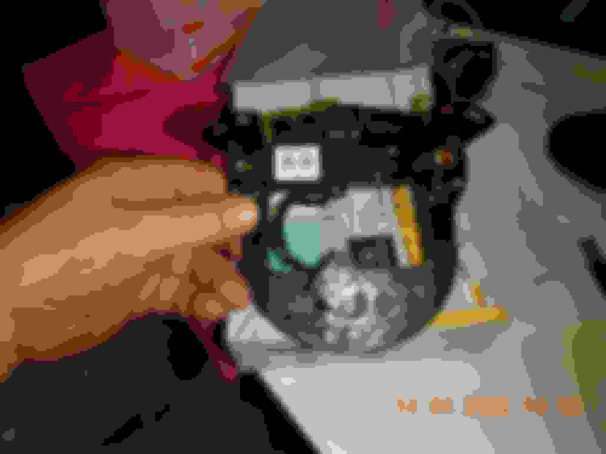
Left photo is using a torch to shine thru the PCB. This is after cleaning.
So I thought the dirt+corossion may jumped and short circuit the copper trace, which is for the DOWNSHIFT button
Nope, there is no real physical short circuit at the PCB trace. Its probably the transistor got tired switching ... LOL.
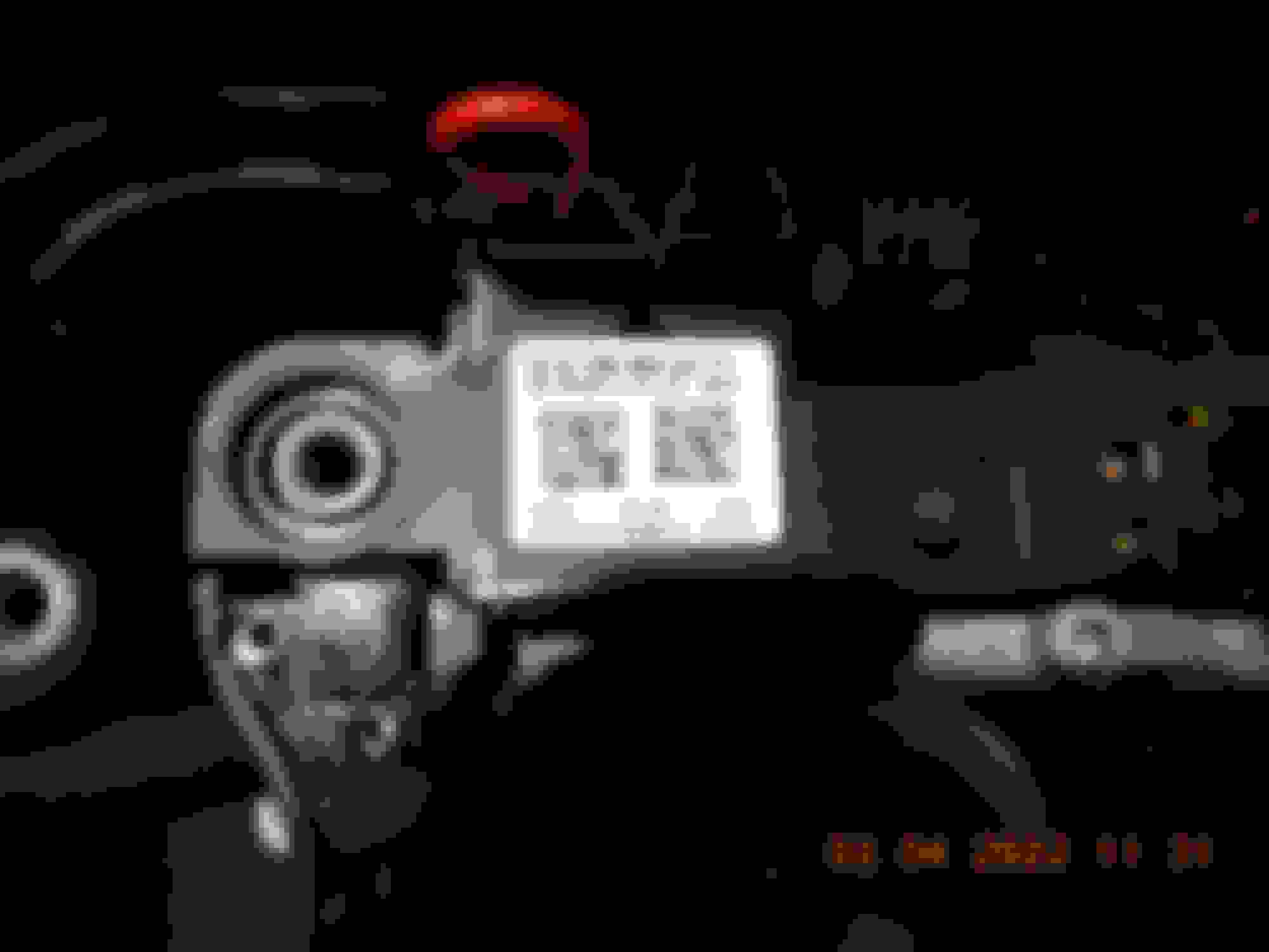
N135 P/N is A 166 464 04 17 . Me must buy new one and it will be probably 60 days special order from MB Indonesia.
Part Number and see the red wire, that is a jumper to permanently short circuit ( ON ) the DOWNSHIFT
Since at part 1 of this mess the DTC was intermittently behaving as momentary ON and OFF and also CONSTANT-ON aka short circuit , the intermittent momentary ON and OFF was the one which made my tranny downshift on its own.
A permanent short circuit or the same as pressing the button permanently, will be declared as SHORT CIRCUIT - MAILFUNCTION and it is good this way.
This switch is then ignored by N135 and N80 module and tranny module Y3/8n4 will be informed and will ignore any request by this condemned switch.
So since I need to wait at least 2 months for the N135 board, I on purpose shorted both the DOWNSHIFT and UPSHIFT pedal switches.
Poke a 2mm square wire and the male pin of the PCB penetrated the copper wire inner diameter...simple and sweet...permanent SHORT CIRCUIT I get
Confirmed, N80 have declared both swithes as BAD.
At the same time I now realized what I assumed as DTC glitch on this post : https://mbworld.org/forums/e-class-w...de-glitch.html
about the WRONG mileage of the DTC event occurence as recorded by module, is probably the N80 hardware itself not updating mileage to A1-Instrument Cluster or some shietty firmware it has.
Let see , 24th March: 35,220 KM actual, but reported as 35,216 = 4KM difference
2nd and/or 3rd April : 35,295 KM actual, but reported as 35,280 = 15KM difference...wow, can't corelate to 24th March one
So, tranny module also confirmed those 2 switches will be ignored. Too bad not specific which/what data is deemed IMPLAUSIBLE. Still, 1 KM mileage data error , but acceptable.
Because I have to remove the steering airbag, DTC appeared too from SRS module N2/10. Look at how and why the heck it is showing same mileage error the same as N80 steering column ??
While a true Xentry is probably very good overall because it can do coding yada yada , it is not the best troubleshooting tool as per data PID.
I seen Audi/VW cars has so much important data PID for : Commanded vs actual , for many parameters. Example fuel pressure low side and high press side and turbo boost.
For W212 Xentry only shows acceptable range for many similar data PID, or no Commanded at all.
Such wrong reported mileage at DTC occurence can be misleading and cause confusion if we do not know the car well enough.
Okey dokey, will report back when I get new N135 interface board.
.
I forgot to explain how I verified the N135 board is the bad boy...... ooops
So, i disconnected both DOWNSHIFT and UPSHIFT, cleared the DTC and still I get the CURRENT DTC again for DOWNSHIFT.
.
This time I disconnected the N135 from N80, I should get LIN based DTC, and I did.
.
I also measured both pins for DOWNSHIFT ( 10.5 kilo ohms ) and UPSHIFT ( 7.6 kilo ohms ).
If DOWNSHIFT has a true mechanical short circuit at its 2 traces, I would read very low resistance.
So , it is very likely the transistor ( the real switching device ) assigned for DOWNSHIFT has a leak or short or whatever.
This is N135 at least a dual layer PCB, and the SMD components are so very very small.... . I gave up.
The micro controller on N135 is this one : https://pdf1.alldatasheet.com/datash...S9S08AW32.html
Downshift paddle input seems faulty or else the Steering stack is questionable.
Surya, we might be able to save you some time and money under 1Hr.
> PART I: considering paddle input
While powered down or disconnected, you measured the paddle switch inputs isolated by 7KR to 10KR to GND.... Good as this says switch status is "unpressed", right?
Now what is the R. value when paddle sw is pressed?
Measure N135 again beyond the PCB pins... do you see an Input value come low or stays high?
pins of suspected circuit
Reconnect power and now... Look at the module live data for switch status while you're toggling both steering switches then shunt strap vs. open.
This should help you narrow down where the Pb is located.
Grest catch Surya
These two issues are precisely what I am eliminating from all my modules to get the equivalent reliability of the SRS controller. MB clearly understands the build quality of good vs. tipsy electronics.
> PART II: considering the stack
In Part I you may or may not have found your smoking gun....
Here we are going to consider that if the fault is logged by the Tranny and not the steering wheel, then the Tranny is unable to reliably communicate with steering button module to fetch buttons status.
This may be caused by any of the stacked "pressed-pins" connections of (side buttons) steering button module or the Steering Colum Module (SCM).
Reworking the N80 (SCM) gave me back the planted steering at Hwy speed vs. tipsy unstable around 0� center... friend with electric rack again: planted straight but light and responsive. Nice!
> Outcome:
If the fault can not be located in Steering Modules Part I/II, then it's CAN disruption bugging the TCU messaging which we know some of that is fostered by MB design choices.
Personally I've resoldered every loose pins, coated ALL my Steering modules plus EIS and nearby Temp module. I understand you are not fan of soldering electronics.... it's simple, practice makes perfect.
Last edited by CaliBenzDriver; 04-03-2022 at 07:22 PM.
While powered down or disconnected, you measured the paddle switch inputs isolated by 7KR to 10KR to GND. Good, this says unpressed sw!
Now what is the R. value when paddle sw is pressed. Measure passed the PCB pins... do you see an Input value near GND or stays high?
pins of suspected circuit
Look at the module live data for switch status while you're toggling both steering switches then shunt strap vs. open.
.
YES, I assumed that too
Under 2 ohms if shorted using alligator clip and within 2 ohms if using the paddle switch itself because the carbon-rubber contact patch is of that resistance if pressed hard.
As I informed ealier, Downshift is logged as Mailfunction ( short to ground ) permanently by N80 module at this time, no matter what. The Upshift can still function normal under live test
By SMD components close by ( or supporting ) to the DOWNSHIFT vs UPSHIFT pins, I notice some difference.
Downshift has 4.7K ohms resistor ( item 2 labeled as 4701 ), while Upshift doesn't.
The item #1 at both switch, I believe it is an inductor as per Google.
Basicaly these 2 mechanical pedal switches are Input devices for the microcontroller. Let's call the process of PUSH-A-PEDAL-BUTTON as analog action, this analog is the only section I can try to figure out.
The port at the microprocessor for the Downshift or Upshift signal probably uses I/O port, here I am lost, this is already IT/Digital/Software domain and no more analog like a relay or contactor I can physically see and test.
Arduino guys can relate better , me no.
Page 79 of the microprocessor in use has the I/O port information https://pdf1.alldatasheet.com/datash...S9S08AW32.html
There are many advantages of using microprocessor as a "switch", smart switch that is.
I experimented on how a switch mailfunction is logged by N135. It surely can notdetect a bad PERMANENTLY-OPEN switch, but it can detect a PERMANENTLY-CLOSED switch as a mailfunction/short circuit and for safety, that switch is then ignored.
With key out of the ignition , N135 board installed at steering. Downshift & Upshift button disconnected, both left and right 6 x 2 multifunction switches cable assy disconnected too..... and I jumped/short the
Upshift button pins. I then turn ignition ON.
I do not know by software how many seconds a PERMANENTLY-CLOSED switch is then deemed as mailfunction , I assume as a transmission gear DOWN/UP switch,which is supposed to work based on 0.5 to 1 second of
Momentary-Closed as a command, perhaps a 3 seconds of PERMANENT-CLOSED switch is then deemed as mailfunction. More so if that switch stayed CLOSED during booting up of N135.
Beauty of a software controlled switch, I guess.
Item 1 thus became a CURRENT or ACTIVE fault is because of the alligator clipped I use to create a PERMANENTLY-CLOSED switch
Item 2 STORED is no more relevant. It is a historical DTC when I removed N135 but power up the N80 during the troubleshooting session.
Item 3 is the CURRENT or ACTIVE fault caused by the N135 logic component/s going banana
Now I realized, why under N135 board Xentry Test , only steering heater and vibration motor are listed.
These 2 are LOADS and not switches. So like the engine computer, I believe N80 or N135 itself can and will do the usual diagnostic signal check for its sensors and other loads at preset time, surely during 1st time boot up.
It is easy to test a LOAD, but there is no way to test a PERMANENTLY-OPEN switch of a Normally Open configuration via software without us assisting.
Now I am thinking back to 6th March, the day the DOWNSHIFT button was not yet a total short circuit and was on its own commanding a downshift.
I have a feeling it wasn't the small dirt at the carbon-rubber switch contact patch that have caused the misery, it must be the N135 component/s itself started going intermittent whacky.
It is actually a good thing that the N135 component related to DOWNSHIFT operation has gone totally whacky on me 2 days ago, because the protection is then created when the DOWNSHIFT
operation is deemed as a mailfunction and is then ignored and disabled....hopefully permanently disabled ( hence the 2 jumper wires at DOWN and UP shift ) till I get new N135 board.
I shorted the UPSHIFT button too as a back up.
My thought process is this :
AA. If ever DOWNSHIFT operation somehow recovered , the jumper wire for it will make sure it shall be deemed a mailfunction again.
BB. I am assuming that the designer of N135 & N80 will not allow any operational input from a DOWNSHIFT, if the UPSHIFT is deemed a mailfuntion. These two switches are related. So Upshift I shorted is as a back-up.
CC. I have proven that the tranny module Y3/8n4 Fully integrated trans control (VGS ) will ignore both DOWN & UP shift command , if any 1 of them is at a CURRENT mailfunction status.
Imagine I am on Jakarta-Bali run. 1,250KM and 20 hours worth of run with 1 overnight stay and a 1.5 hours ferry crossing.
If this DOWNSHIFT-on-its-own occured during this run, I would be in trouble.
I would carry my Xentry Laptop if not Autel MS906BT, but I do not carry with me the type of Torx tools and other small supporting tools I needed to perform similar fix of 2nd - 3rd April.
If i were troubleshooting this at a hotel parking lot instead of my own home, surely I would be a pissed state of mind
So this N135 issue is a blessing for me... LOL.
I was reading about microcontrollers few hours ago. Damn , these are what can go wrong without being actually a defective unit : http://www.ladyada.net/wiki/microcontroller_annoyances
Flash corruption from bootloaders
EEPROM corruption from brownouts
Now I see why there are so many capacitors and resistors supporting the switches on N135.
Even on PC, re-installing drivers or programs can help a lot.
On my GoPro cameras, re-installing firmware helps too, when it often hang.
For all I know, this N135 probably can be re-flashed for its firmare/whatever and may recover. But I guess the question is how to do it ?
I think I better get into Aurdino to learn a little bit about MCU, that would help a great deal for my thought process if I come across processor related issues.
"As I informed ealier, Downshift is logged as Mailfunction ( short to ground ) permanently by N80 module at this time, no matter what.
The Upshift can still function normal under live test."
The above says:
N80 SCM is logging button stuck error.
N135 button module has no button error.
How is the N135 steering wheel module connected to N80 intermediate steering column ??
> Fix your N135 connector pins to give module a chance to initialize and communicate reliably with SCM through long clock-spring ribbon. Clear N80 error to let it resume Downshift signaling.
I must brave up to remove N80 heheheeh. But will do it somehow for know-how sake.
But I still believe the N135 alone is the bad dude.
Me at will, creating short/jumper to Upshift button to make it a CURRENT mailfunction status showed that N135 can communicate well with N80 and can reset that mailfuntion status when jumper removed.
I also test allother12 buttons live data check. So there is no reason only the Downshift to be stuck in mailfunction mode (without the pedal switch assy connected), unless somehow at N135 some component deemed it so.
N135 to N80 is a LIN data and its a summary of conditions as reported by N135, so Downshift switch status is part of the data package. There is no way the LIN sentence only muted the downshift switch status heheheh
Yes I totally agree:
N135 has problems.
Last edited by CaliBenzDriver; 04-04-2022 at 12:24 AM.
I was fortunate MB Indonesia does have stock of N135 at its usual price 3 to 4x of Europe's price.
Simple test
.
.
.
If any SHIFT button pressed, surely it is the carbon rubber switch resistance we read, 2ish Ohms, be it on a bad N135 or a good one
.
For Cali with thanks....
Do you have photos of the LEFT & RIGHT multifunction switches PCB when you solder-assist them ?
I just realized last nite when doing more intensive test on the old N135 board, There are few switches which are 2-in-1 so to speak , they are : LEFT-RIGHT and UP-DOWN .... because they are actually sharing same activation wire from N135.
I am wondering how does the computer differentiate LEFT to RIGHT ? ...perhaps there is an added resistor at the switch assy itself ?...or what ?
I show you what I mean : See wire no 10 and 5
Last edited by S-Prihadi; 04-18-2022 at 08:54 AM.
Reason: ADD INFO
I am quite certain the N135 on its own is programmed to take decision or CAN do safety strategy, without needing N80 steering column to do it on N135 behalf.
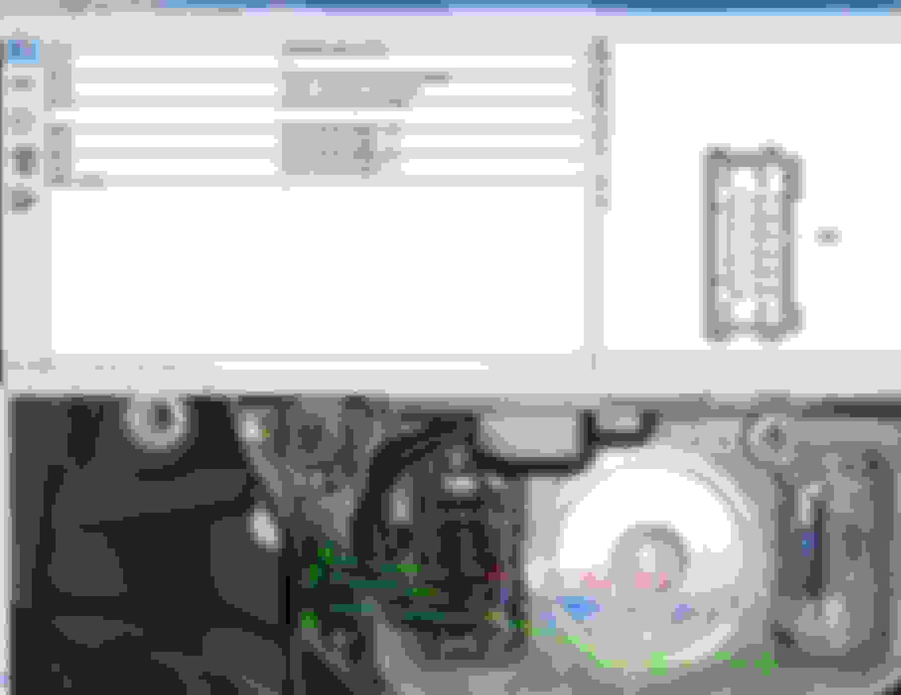
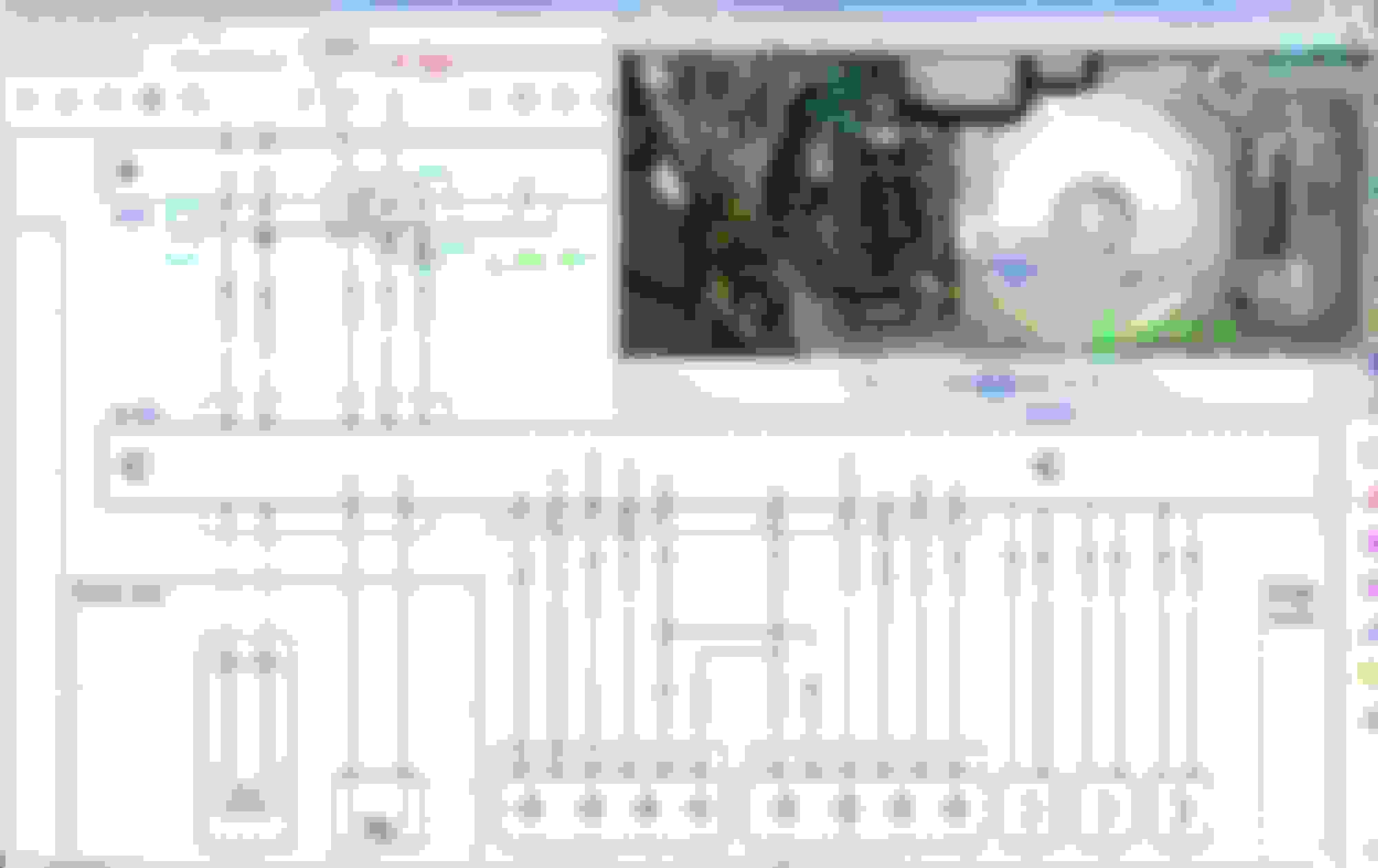
Below is my old N135 signals , as we know only the downshift is the defective function/logic on this N135. All other functions work well.
The green ( OK button ) and yellow/brown ( TEL button ) signals appears to be the diagnostic signal when N135 is awake. It is not a LIN data signal.
Activate any* switches by shorting to ground, meaning this is a Pull-Down type switch-signal ........ the N135 wakes up and created those diagnostic voltages dance... but I don't see diagnostic signal for UP-SHIFT (Red channel ) or DOWN-SHIFT (blue channel).
If I shorted/activate UP-Shift button, diagnostic voltages dance appears...but at Green ( OK Button ) and Yellow ( TEL button ) only
If shorted/activate DOWN-Shift button, no diagnostic voltages dance anywhere..because that signal path is bad and probably being shut-down by N135 , hence I marked red asterik on the : " any* switches"
OK button (Green channel ) being pressed meaing signal or voltage will be pulled down to ground near zero, will also cause yellow ( TEL button ) diagnostic signal to go to 6.3V, instead of their usual 8.5ish volts signals
As to why I said : " I am quite certain the N135 on its own is programmed to take decision or CAN do safety strategy"
is because I would think N135 is already on its own shutting down function of UP-Shift button too, because DOWN-shift deemed bad....otherwise Red Channel ( UP-shift ) would get diagnostic signal too like OK and TEL buttons Green-Yellow channels.
So N135 is not a simple switches Interface only board, it has logic function built in to it too.
Upon powering up N135, green channel ( OK Button ) and Yellow channel ( TEL Button ) stand by itself at 11.2 is volts, but the Blue & Red channels OK/TEL buttons is sleeping at zero volt.
Too bad I did not carry out the same experiment with the new N135....I do not want to short it by accident
Anytime I waken up the N135 by pressing any working buttons, the diagnostic signals only last about 1-2 seconds and it will stand-by /sleep again.
I can not detect any LIN data activity from pin 6 at B1 connector when N135 is awake. I guess N135 will need N80 Steering Column to command something to it before I can see any LIN data activity.
.
At the 10 pins connector of N135 for LEFT & RIGHT multifunction switches, I can only get diagnostic signals from other pins, except :
#8 is ground, so ignore it
#3 is labeled as 58, that is illumination, so ignore it.
#1 and 5 <<<< these 2 I think need more upstream computers to be online with N135 before I can see any signals. #1is I think and I am uncertain here......... is the Voice Command Button. WIS does not have label information for : U-ML-L ( left switches set ) and U-MFL-R of below.
I think #1 needs to communicate with a telephone being bue-tooth-ded to our Command Display unit first.......if I want to see any signal from it.
. Pin #5 U-ML-L ( left switches set ) also I can't see its diagnostic signal. Maybe this one need A1 Instrument Cluster to communicate with N80>>N135 before I see any signals ?
.
Such a low power use this N135, only 0.12 watts.
Okey, testing completed. Hope this can help others...........
ADD: I think the diagnostic signal I speak of is commonly called as Bias Voltage by many automotive techy.
steering wheel buttons PCB
Above are the before/after button boards I've reworked. Solderless pins on unprotected components got soldered and protected by a brushed-on silicone film. This is what you can observe on modules (SRS, Distro+,...) MB wanted to stay reliable.
This circuit is a standard keyboard matrix ladder made of resistors and backlit switches. The integrated controller figures which switch is pressed by reading the total R value. It is then able to transmit the code of the matched key over serial LIN I/F.
bingo
In OP#1 you are showing us an example of how a short circuit to ground effectively developed. Both copper traces were factory coated with a green layer... proof that it's inadequate.
ground plane is needlessly 1/2 mm apart from unprotected pads
Oxidation bridges don't have to grow between pins to find the ground potential. GND is all over the place to act as RF shield on these basic DC boards.
reworked SCM: soldered & coated
The boards that I have resoldered usually show brighter LED and respond faster as seen with DCU, SCM & EIS.
So I'm simply aiming for 100% coverage.
Last edited by CaliBenzDriver; 04-18-2022 at 05:10 PM.
steering wheel buttons PCB
Above are the before/after button boards I've reworked. Solderless pins on unprotected components got soldered and protected by a brushed-on silicone film. This is what you can observe on modules (SRS, Distro+,...) MB wanted to stay reliable.
This circuit is a standard keyboard matrix ladder made of resistors and backlit switches. The integrated controller figures which switch is pressed by reading the total R value. It is then able to transmit the code of the matched key over serial LIN I/F.
 04-03-2022, 04:04 AM