When you click on links to various merchants on this site and make a purchase, this can result in this site earning a commission. Affiliate programs and affiliations include, but are not limited to, the eBay Partner Network.
I believe I won't be adding anymore sensors input for my Banks Gauge.
The final configuration as follows ;
MODULE 1 : 4 channels analog module.
1 - Engine Oil Pressure. Installed at engine's oil pressure test port.
2 - Engine Coolant Pressure , installed at rear of engine block output for HVAC heater core.
3 - Aftercooler coolant pressure, installed at its 12V DC pump output
4 - Vacuum pressure provided by engine's vacuum pump. Taken at the brake booster test port. Today new pressure sensor installed, the old one drifted 5 psi and was a 50 psi-Absolute. New one is 15psi-Absolute.
====================
MODULE 2 : Unit 1, 4 channels Thermocouple module
1 - Tranny oil pan skin temperature. As Tranny Oil temperature
2 - DIFFerential casing skin temperature. As DIFF Oil temperature.
3 - Engine oil sensor adapter's skin temperature. As Engine Oil Temperature.
4 - Coolant temperature for aftercooler which is the skin of the pressure sensor adapter for aftercooler coolant, which so happened this path is also output of aftercooler mini radiator.
This then reads the cooled aftercooler's coolant before entering AfterCooler Core to be heated again by charged air.RECENTLY ADDED.
==================
MODULE 3 : Unit 2, 4 channels Thermocouple module
1 - Front Right, brake caliper temperature.
3 - Coolant temperature of Bank 1 ( right side ) turbo's coolant OUT.
This can act as back up to OE engine's coolant temp and at the same time seeing when and if turbocharger get too hot coolant wise.
Reading is at the aluminum pipe of the turbo coolant OUTLET pipe, as close as possible to the turbocharger.
4 - Ambient Temperature of the Engine Bay. Also called as UnderHood Temperature. RECENTLY ADDED.
Sensing location is at Bank 2 ( LEFT side of engine ) close to aftercooler, at the air path of the radiator fan.
I have replaced new thermocouple wire/sensor of the Tranny and the DIFF to use Omega brand and a thicker 24 AWG version. https://www.omega.com/en-us/temperat.../p/TT-K-24-100
It is better for such long distance run to the rear of the car and more accuracy over wide temperature band compared to previous one thinner and probably China made.
Now the entire thermocouple wires are all by Omega, except :
Module 3 , Unit 2. Channel 3 - Coolant temperature of Bank 1 ( right side ) turbo's output. Its a higher end thermocouple from China with stainless steel braid jacket. So far so good.
I have improved the tranny's thermocouple method of "sticking" sensor wire end to oil pan skin.
Use to be naked thermocouple wire end, now I use cable terminal lug and screw + nut to secure it, unlike previous one I only stick on using 3M alu foil.
3M Alu foil still being used is to reduce cooling effect by wind velocity at high speed to the sensor sensing tip.
The DIFF thermocouple gets a better cable lug too, aside from new thicker Omega brand thermocouple wire.
Since I did TRANNY + DIFF + Rear Caliper at one go, I can improve the wire routing and protection.
Themocouple wire has its weakness.
01. Weakness or technical consideration for thermocouple wire is : to work within its gauge/core size resistance vs total wire length. Thermocouple wire is not a powered sensor. https://www.omega.com/en-us/resource...ly%20is%20fine.
02. The temperature sensing is not only at the end of the naked cable core, but the entire cable core. They are galvanic battery basically, produce millivolts when temperature rise due to different metals used as + and - .
So I have to protect from heat the entire thermocouple wire-sensor which runs under the car, if I want to be able to read accurately a device temperature which maybe cooler at times, than engine bay ambient temperature.
Note 1, each thermocouple wire get a small 3mm fiberglass sleeve up to a point.
Note 2, each thermocouple also get 5mm heat-shrink tube to further insulate its 3mm fiberglass sleeve. I do not shrink much the heat-shrink, I keep it "loose" for insulation airspace.
Note 3, when nearing engine bay, all 3 thermocouple wires only....will then be cramped into a 5mm fiberglass sleeve.
Note 4, the 5mm fiberglass sleeve then get 10mm heat shrink tube, which I do not shrink until the last 30cm portion.
The sensor wire routing is not actually into engine bay, but at the side near the inner fender wheel well of right front tire. I want to avoid engine bay heat as much as possible.
DONE for Tranny + DIFF + Rear Brake Caliper at Thermocouple 4 Channels Module no 1.
===============
Today, Thermocouple 4 Channels Module no 2 added, I have run the thermocouple sensor wires last year.
The thermocouple inter-connectors are not waterproof. So I used electrical tape just to protect from water droplets, if any. Yellow taped ones are the Module no 1 sensors. White taped ones are Module no 2 sensors.
A is the wired connection to car interior, for the Banks twin gauge display.
1 to 3 are all the 4 channels Analog and Thermocouple modules as explained.
4 is wire to module no 4, the Air Mouse in front of the radiator.
5 are set of old thermocouples, 4 units, which I installed at various locations of the HVAC hose/pipe some years ago. It will come handy some day.
=====================
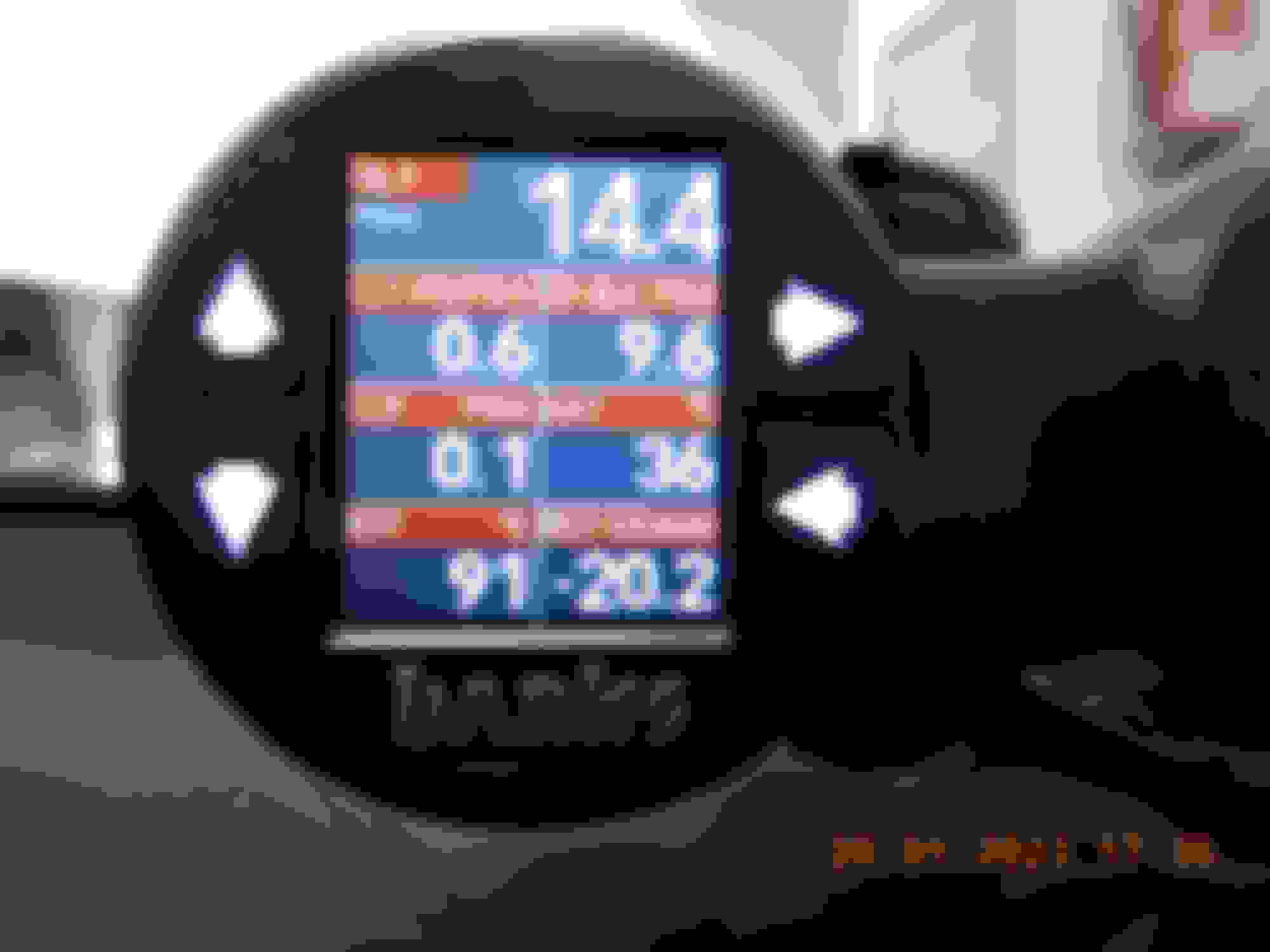
MODULE 4 : The Airmouse or weather station.
This module tells me how much I loose engine power because I live in a hot and humid country where my ambient air density does not reach SAE's J1349 STANDARD DAY atmospheric condition.
SAE J1349, which is the most common correction factor, uses an ambient pressure of 14.4 psia, an ambient temperature of 77 deg F, and a relative humidity of 0%, which results in an ambient Air Density value of 72.2 lbs./1000 ft^3. https://official.bankspower.com/dens...F1000%20ft%5E3.
Air Density value of 72.2 lbs./1000 ft^3 in metric is 1156.53 KG per cubic meter.Me usually at 111KG only or 6% power loss
=====================
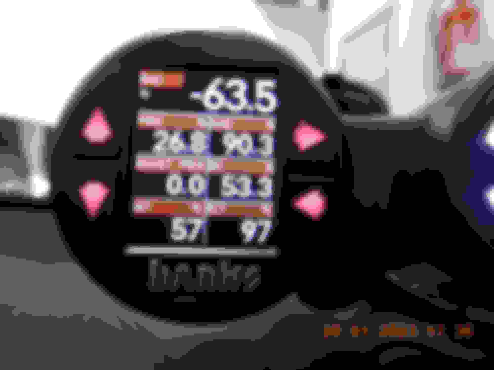
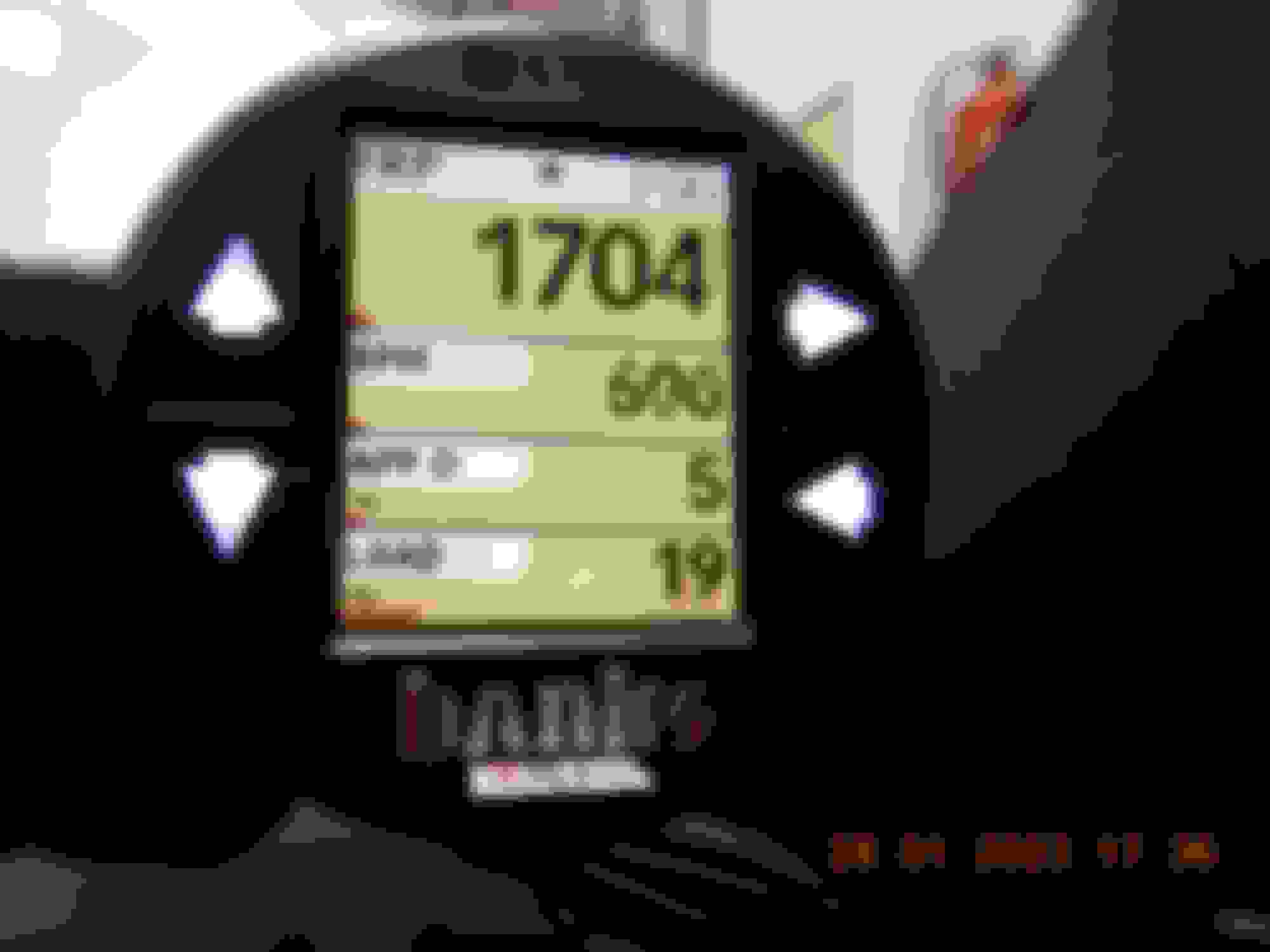
The data I log and assign for display
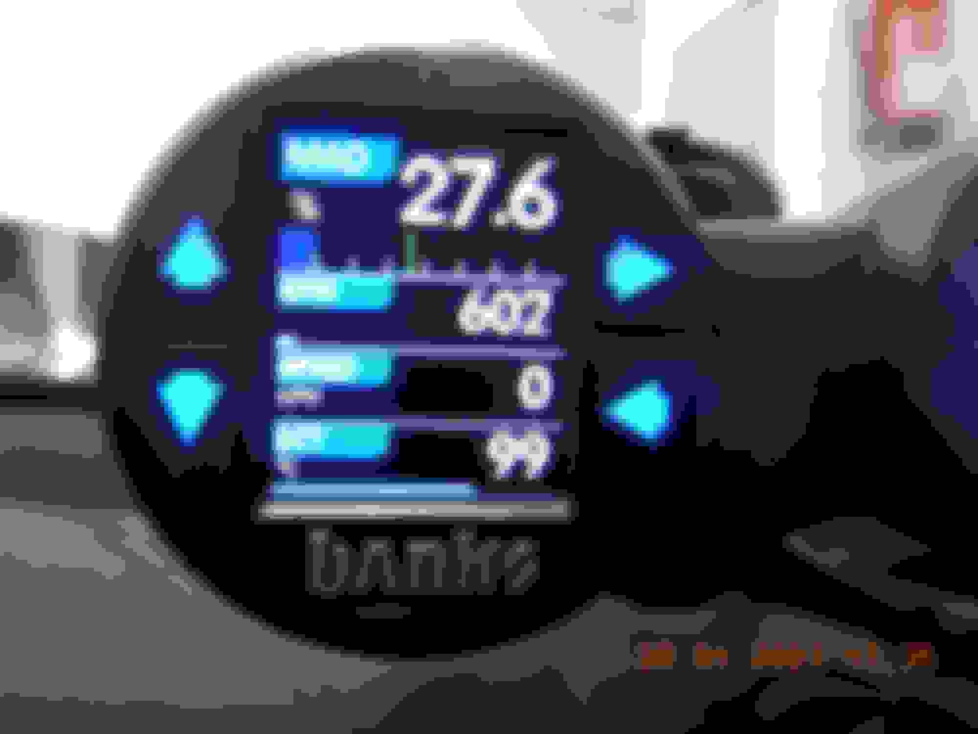
MAIN DRIVING DISPLAY PAGES. Each display has 5 custom pages we can set to have up to 8 data perimeters per page.
LEFT DISPLAY , slave. All temperature in Celcius
TRNS T = Tranny oil temperature
EOT = Engine oil temperature
DIFF-T = Differential oil temperature
TMP-2A = Front Brake Caliper ( Thermocouple module no 2, channel A ) << We can not use CUSTOM name, many prepared ones ready to use, but no Caliper temp
TMP-2B = Rear Brake Caliper ( Thermocouple module no 2, channel B )
U-Hood = Under Hood or Engine Bay ambient temp
CAC-WT = Charge Air Cooler Water Temperature. <<< Coolant temperature for aftercooler which is the skin of the pressure sensor adapter for aftercooler coolant, which so happened this path is also output of aftercooler mini radiator.
This then reads the cooled aftercooler's coolant before entering AfterCooler Core to be heated again by charged air.
RIGHT Display, Master & Logger
RPM
ECT = Engine Coolant temp
Oil P = Engine Oil Pressure
CT-OUT = <<<< Coolant temperature of Bank 1 ( right side ) turbo's output.
This can act as back up to OE engine's coolant temp and at the same time seeing when and if turbocharger too hot coolant wise.
Reading is at the aluminum pipe of the turbo coolant OUTLET pipe, as close as possible to the turbocharger.
IAT = Intake air temp. This one is read by engine computer as the COOLED air after aftercooler into intake manifold. The sensor is at the aftercooler output side.
CAC-WT << I will replace this with Engine Coolant Pressure , installed at rear of engine block output for HVAC heater core.
BATT = This is from ECM. There is another BATT-D which is battery voltage of diagnostic port aka Rear SAM.
AAD at 90.3% is what I said by :
where my ambient air density does not reach SAE's J1349 STANDARD DAY atmospheric condition. Air Density value of 72.2 lbs./1000 ft^3 in metric is 1156.53 KG per cubic meter.Me usually at 111KG only or 6% power loss
BOOST PSIG = The turbo boost or manifold pressure above absolute, in PSI.
RH = Relative humidity %
IAT = Intake air temp. This one is read by engine computer as the COOLED air after aftercooler into intake manifold. The sensor is at the aftercooler output side.
ECT = Engine Coolant temp
RIGHT Display, other page or page 2
FRP = High Pressure Fuel raill pressure in PSI
APP D = Accelerator Pedal D
Load = Engine load
LEFT DISPLAY , other page or page 3.
MAD = % Manifold Air Density: Manifold Air Density expressed as a percentage of the selected standard day.
SPEED = Speed over land from car computer, in KM per Hour
ECT = Engine Coolant temp
RIGHT Display, other page or page 3
RPM
ECT = Engine Coolant temp
ABSTPS = Throttle Position Sensor, absolute
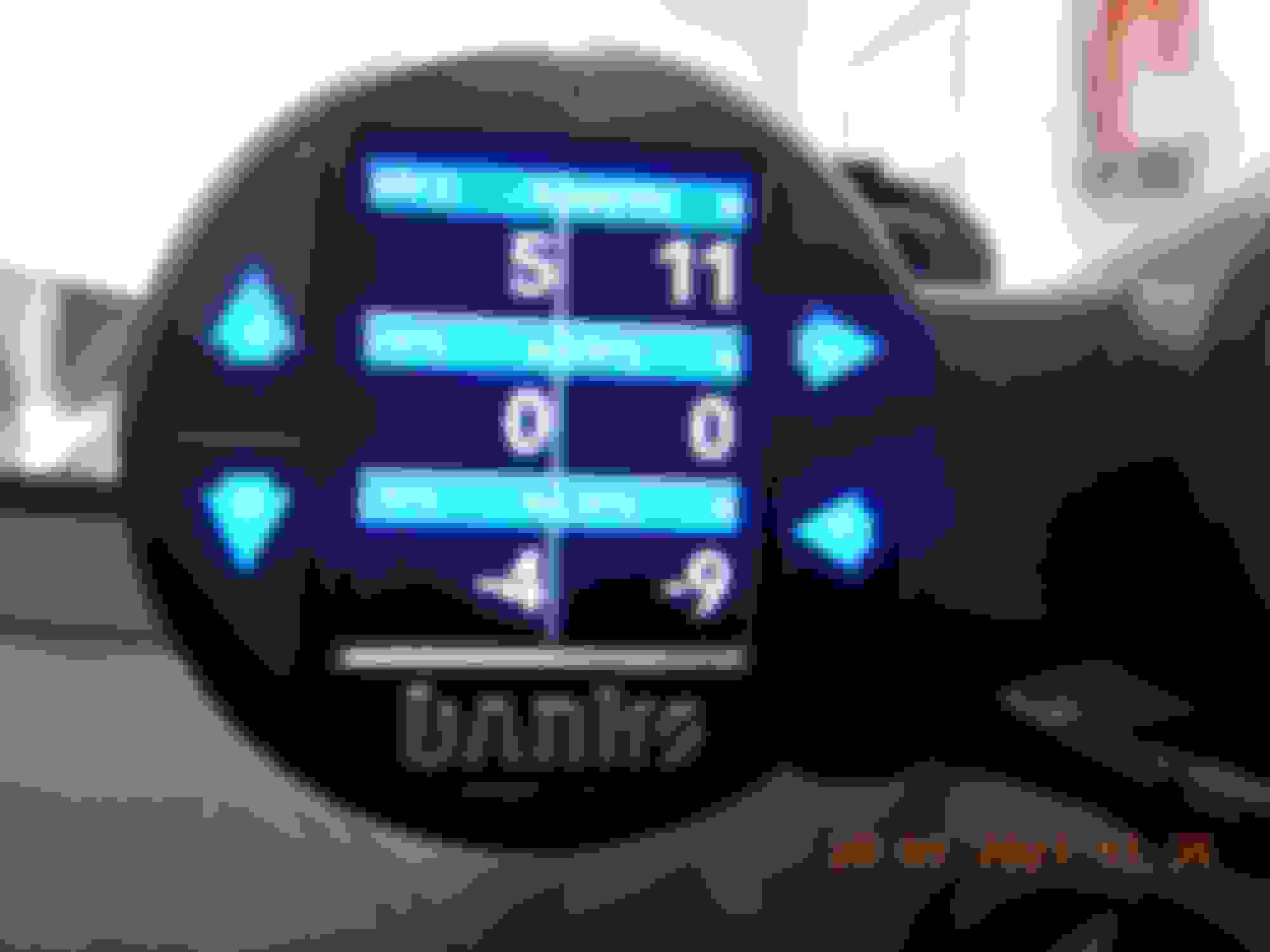
STFT1 = Short Term Fuel Trim, Bank 1 ( right side )
STFT2 = Short Term Fuel Trim, Bank 2 ( left side )
LTFT1 = Long Term Fuel Trim, Bank 1 ( right side )
LTFT2 = Long Term Fuel Trim, Bank 2 ( left side )
LEFT DISPLAY , other page or page 4.
APP D = Accelerator Pedal D
ABSTPS = Throttle Position Sensor, absolute
STFT1 = Short Term Fuel Trim, Bank 1 ( right side )
STFT2 = Short Term Fuel Trim, Bank 2 ( left side )
LTFT1 = Long Term Fuel Trim, Bank 1 ( right side )
LTFT2 = Long Term Fuel Trim, Bank 2 ( left side )
RIGHT Display, other page or page 4
RPM
ABSTPS = Throttle Position Sensor, absolute
IGN TM = Ignition Timing ( in degrees )
EVAPCM = Evap Purge Commanded. This is the fuel vapor purge
Load = Engine load
021/2 = Voltage of narrow bandwith Oxygen Sensor no 2 of Bank 1 ( Left )
022/2 = Voltage of narrow bandwith Oxygen Sensor no 2 of Bank 2 ( Left ) NOTE : Too bad Banks Gauge can not translate my engine's computer Lambda value ( wideband 1st oxygen sensor , Bank 1 and Bank 2 ) correctly. So I do not display or log it.
LEFT DISPLAY , other page or page 5. Maximum is 5 pages.
Oil P = Engine Oil Pressure
CLT-PRS in PSIG = Aftercooler coolant pressure, installed at its 12V DC pump output
CP-BLK in PSIG = Engine Coolant Pressure , installed at rear of engine block output for HVAC heater core.
CCP in PSIA= In label it is suppose to mean CrankCase Pressure. I choose it due to limited naming database, but I actually use it for : Vacuum pressure provided by engine's vacuum pump. Taken at the brake booster test port.
Since the sensor is an absolute one hence PSI-A , Zero PSI reading means a good vacuum. My gauge shows 0.1 PSI and that is as good as zero.
If engine if off and vacuum gone, it will read atmospheric pressure of 14.7 psi at sea level. So the nearer to zero is better value. Pressing a brake deep and hard will consume approx 2 psi per push down but vacuum pump will recover vacuum value fast.
This data will tell the state of health of the engine driven vacuum pump or any other vacuum loss and for my engine that means for the turbocharger wastegate will stay open/leak if vacuum is not enough or leak bad.
AAT = Ambient Air Temperature. This is the same as MB outside air temperature, but the Module 4 - Air Mouse/weather station can also provide AAT information.
EOT = Engine Oil temp
BST-VA inHg = Boost and Vacuum of intake manifold in PSI and Inch Hg
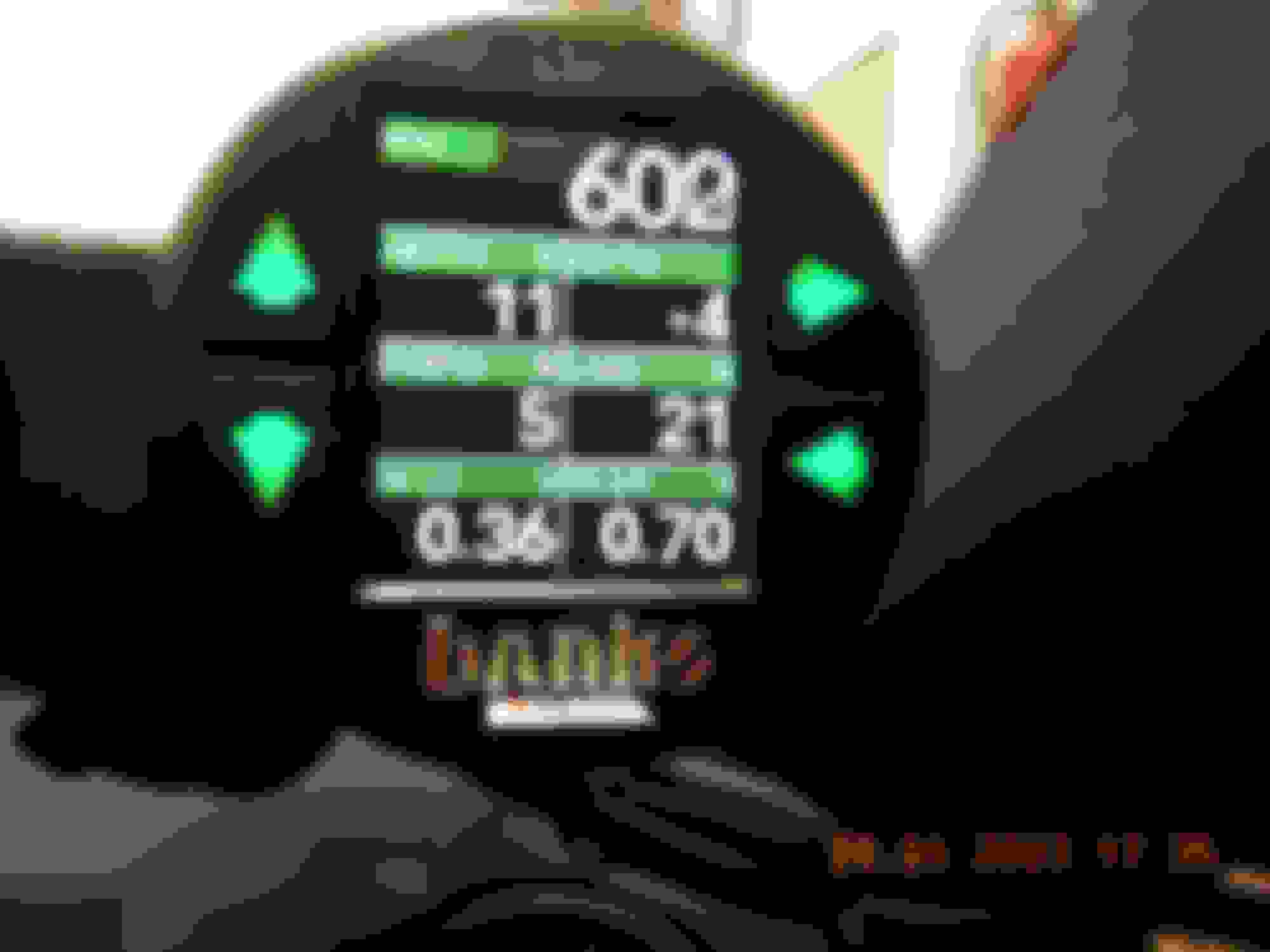
RIGHT Display, other page or page 5.
RPM
ECT= Engine Coolant temp
BST-VA inHg = Boost and Vacuum of intake manifold in PSI and Inch Hg
IAT = Intake air temp. This one is read by engine computer as the COOLED air after aftercooler into intake manifold. The sensor is at the aftercooler output side.
CAT1/1 = Exhaust gas temperature as read by Lambda sensor ( wideband 02 sensor ) no 1 ( front ) at Bank 1 ( right side )
CAT1/2 = Exhaust gas temperature as read by Lambda sensor ( wideband 02 sensor ) no 1 ( front ) at Bank 2 ( left side )
CAT2/1 = Exhaust gas temperature as read by narrow band 02 sensor no 2 ( rear ) at Bank 1 ( right side )
NOTE : There is no menu in Banks Gauge for CAT2/2 or Exhaust gas temperature as read by narrow band 02 sensor no 2 ( rear ) at Bank 2 ( right side )
I think this is OBD2 limitation. Xentry can show temperature of CAT2/2.
CAT is actually catalytic converter, but I call it exhaust gas temperature for easier understanding.
=======================
This is the crappy side of being in the tropics and turbocharged car with lame cooling system.
Ambient air of engine bay or underhood temperature is very hot during traffic jam. Below is a stand still , but engine revved up.
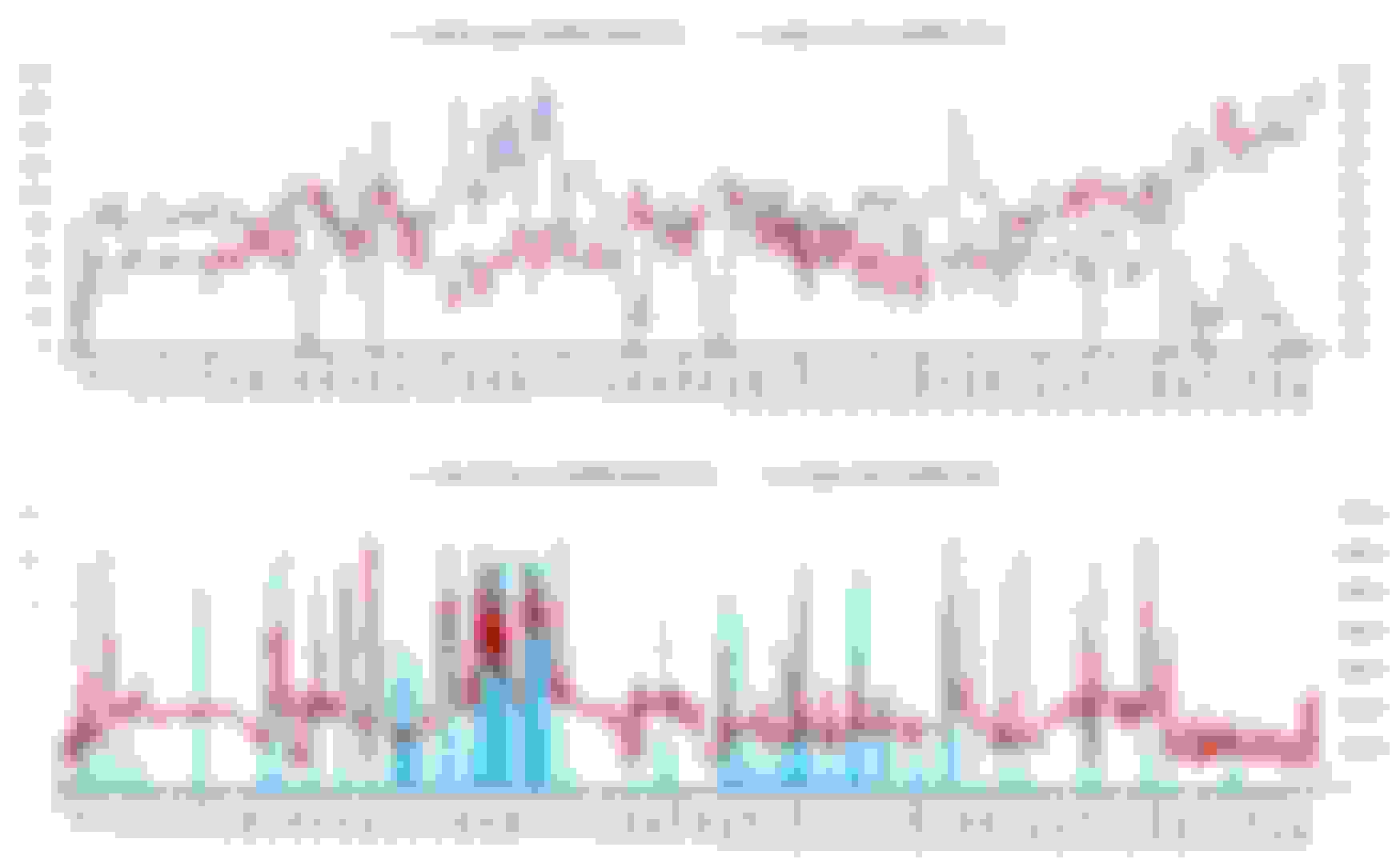
Below is 5Hz data : The green trace I hand marked is to show, M276 3.0 TT water pump at idle speed is too lame.
I revved up engine at 4,000 RPM to 100C coolant temp at marker 493 and I let engine to idle, by marker 534 ( or 8.2 seonds later ) coolant temp shoot up to 105C.
I then blip-blip the RPM up for a while at marker 575 to 739 or 32 seconds to speed up water pump spin, then coolant temp drop fast from 105C to approx 98C.
Let engine idle again and coolant temp rise up again to 101C and took many minutes later to cool down to 95C.
Actually ambient temp was 29C at the start , but the outside air temperature sensor at the bumper is always heated up by engine bay temperature... LOL.
At traffic jam crawling speed, intake temp of 60C is common for my city.
I forgot to explain.
Tranny oil pan is a serviceable item and need to be removed when doing tranny oil change.
I have added extra 30 - 40cm long thermocouple wire run for this allowance.
So tranny oil pan can be removed and hanged while being cleaned. Thermocouple tip no need to be removed from oil pan.
With tranny pan normally cleaned away from the car you can add a connector to disconnect your additional thermocouple ?
ISM shifter + key authentication...
translated as "Limp modes + No Starts"
Built with 2x rows of amazing pins, an outside vent pipe and unprotected circuit board
What sort of sealant compound is used to glue these modules shut ? ISM closeup still missing in my surgery collection.
N,o I do not want inter-connect for thermocouple wires. They are not waterproof those connectors and
I can not introduce non compatible metals in the middle of a thermocouple wire run if say I use other kind of waterproof connectors.
Yes please Cali, do the surgery : ISM closeup still missing in my surgery collection.
First Test Drive to create FALSE misfire and at the same time test these Bank Gauges too.
I attached 2 of the log files for those who wants to do the same kind of logging.
Log134 is COLD start to warm up and 1.4KM to the paid highway entry, and then engine kill. Near 5 minutes.
Log135 is 30 seconds later I started the car again and enter the paid highway and did my test drive for 63 minutes.
My logging technique is as follows : (to make sure Banks Gauge starts logging well before I crank my engine.)
Press to turn ON Banks Gauge, and when it already boot up and starts logging, I then started the engine.
The Banks Gauge will auto turn ON and OFF based on RPM signal, but that means I loose 10 ish seconds at start and I get 10 seconds of useless ending data if I choose that auto ON feature.
Accuracy check for the thermocouples. Using MB original outside/ambient air temperature ( AAT ) as reference temperature.
Yellow highlighted ones are original temperature sensors of the car.
Car engine been off at least 48 hours.
Column AO, it is the China made 0.3mm diameter thermocouple, all others are 0.5mm Omega.
Column AO Coolant Temp - Engine Out is actually bank 1 (right side ) turbocharger coolant outlet pipe skin temperature.
DIFF Fluid Temp is the longest thermocouple wire run. Highest positive offset.
Coolest one or more minus offset, is the TMP-2A, front brake caliper.
I am surprised by the accuracy of the oxygen sensors ambient temperature reading.
Overall I am happy with the thermocouples accuracy.
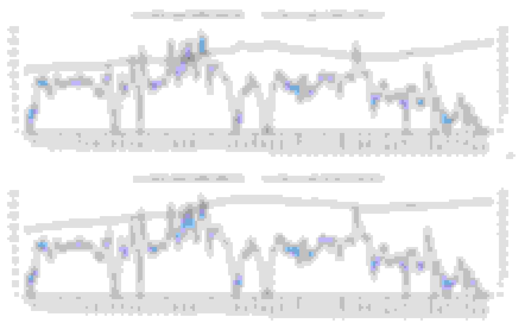
Front Brake Caliper TMP-2A and Rear Brake Caliper TMP-2B. From Log135
The interesting part here is it seems front brake caliper ( not rotor disc ) being so big compared to rear one, is able to remove its heat faster or get hot slower, either way.
The more interesting part is how hot is the engine bay ambient temperature when NOT at 80 KM/H or faster.
Specific to my engine M276 3.0TT ( M276.820). The aftercooler works best past 80KM/H too in my tropical country with average ambient temp 30C and my city bad traffic.
This test run is 10PM and not at traffic jam yet. IAT can be as high as 60C at bumper to bumper traffic.
 01-28-2023, 12:17 PM


 where my ambient air density does not reach SAE's J1349 STANDARD DAY atmospheric condition.


")