When you click on links to various merchants on this site and make a purchase, this can result in this site earning a commission. Affiliate programs and affiliations include, but are not limited to, the eBay Partner Network.
01. Power delivery to components on the car need both positive wire and negative wire. If either one intermittent bad or loose or over oxidized aka green crusty, modules will go banana.
02. Most people focus on GROUND wires because it is a shared wiring set and is at often the un-friendly area of the car.
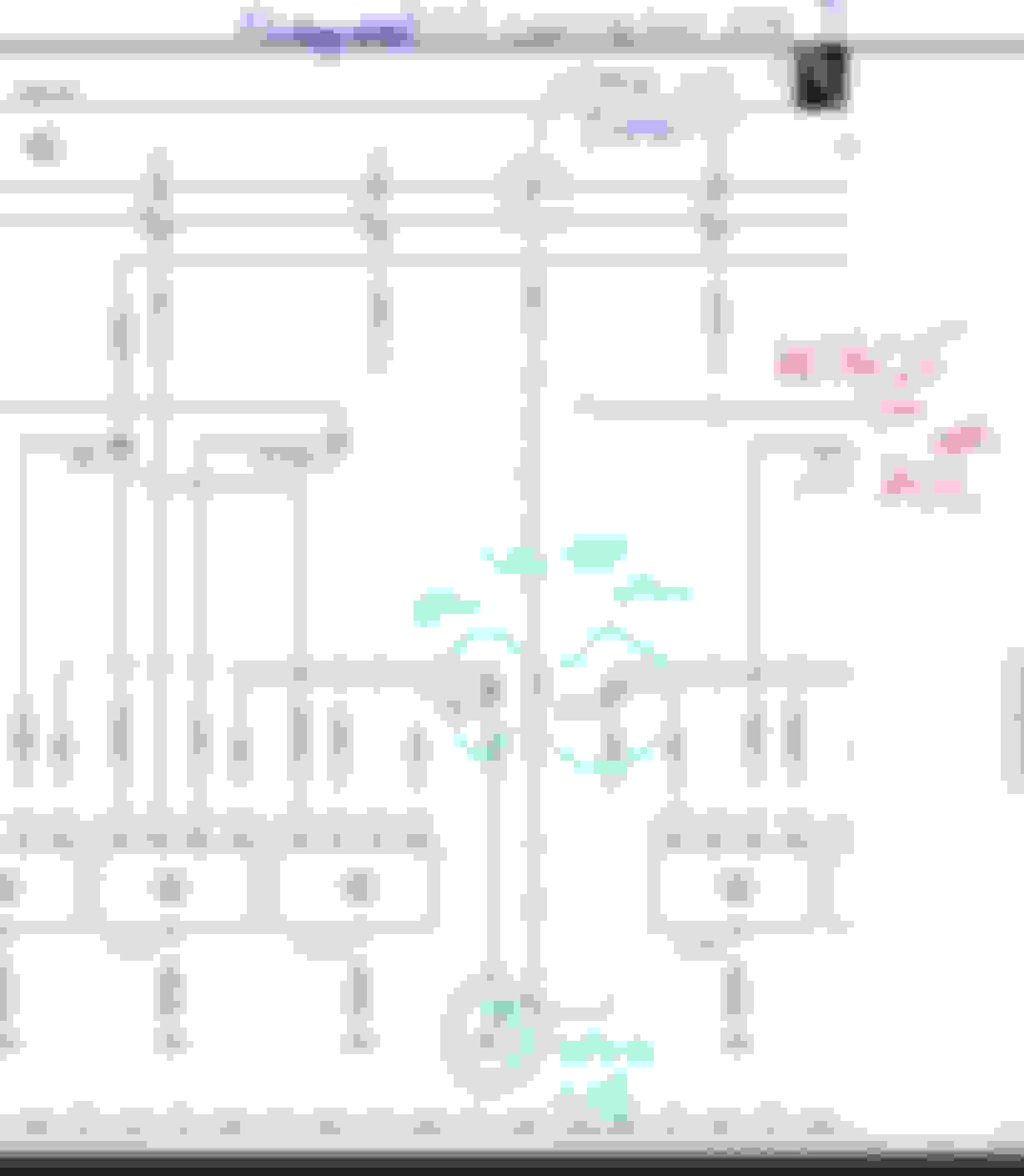
Positive power wires routing as follows for our engine computer. Based on your M276 3.5 NA engine.
Front SAM Fuse 24 to X26 connector block pin #7 to Z735z2 splice and feed +12V direct to engine components, this does not go to the ECM it goes direct to 3 units COP, COP4, COP5 and COP6 at Bank2 or Left side bank.
The very same Z735z2 (+12V ) also supplies or spliced to Y49/4 Left intake camshaft solenoid and Y49/6 Left exhaust camshaft solenoid
Z735z also spliced to B6/4 Left intake camshaft hall sensor and B6/6 Left Exhaust camshaft hall sensor.
Front SAM Fuse 22 to X26 connector block pin #6 to Z736z1 splice and feed +12V direct to engine components, this does not go to the ECM it goes direct to : ........... You trace the wiring diagram yourself.
Tips : 3 components + 4 components
Front SAM Fuse 23 to X26 connector block pin #5 to Z738z1 splice and feed +12V direct to engine components, this does not go to the ECM it goes direct to : ........... You trace the wiring diagram yourself.
.......... to 3 units COP, COP1, COP2 and COP3 at Bank 1 or right side bank.
.......... to 4 other componentz, coordinate 41G
Front SAM Fuse 27connector 4i pin #4 to engine computer F connector pin 16. This is the power supply for ECM which is always ON/HOT if on my engine, would be identical to yours too, after all both are M276.xxx
This is dedicated wiring from Front SAM, to ECM without any splice.
There is another one. Front SAM Fuse no 25 , output from Front SAM connector 4i #10 2.5mm red-yellow and then spliced called Z7/73z1 to 3 wires of 1.5mm red-yellow and to
ECM connector F pin #5 , # 3 and #1. I suspect this is for the injectors because the cable size is so obvious for high power use.
Now aside from the grounds (-12V ), pay attention to +12V
=====================
Grounds for ECM
You have to find the ground stud called W16/5 by hook or by crook. By schematic, that wire lug/eyelet will have total 4 wires.
If I may suggest and this will be useful for the car database, you map out what fuses of ECM feed what components.
I made this some years back, so I do not need to get migraine from reading/tracing the schematic of ECM ( 3 pages ) and Front SAM ( 10 pages !!! )
I spent yesterday taking apart the driver side wire harness, looking for any weak connections. Found the two ground wire splices, one with 5 wires all brown and white and one with 4 wires all brown going to ground at the front driver side valve cover. W11/3 I think. Cut the factory splice, soldered and put a hog ring around both, thicker steel wire just to add clamping force after soldering the bundles. Double shrunk wrapped them both and fired the car up. Misfires at first then they went away. I ran it 15 minutes or more with no misfires. I am all excited. Drove up and down my driveway using pretty good throttle with no misfires. OK, I went and had dinner then came back out to test drive it. Misfires at start up, tried to drive it and check engine light due to misfires came on right away. I am pretty discouraged at this point.
Thanks for refreshing and laying out all the possible places this problem might be Mr. Prihadi, I am not an electrical guy so I really have to study up before chasing electrical issues. I really wish I had not taken time to button all the wires back up, taped strapped and ready to go back on the road only to need to tear all that apart again. I have another commitment today so it need to sit for a bit.
Your help is amazing, it may just lead me to an answer.
I spent yesterday taking apart the driver side wire harness, looking for any weak connections. Found the two ground wire splices, one with 5 wires all brown and white and one with 4 wires all brown going to ground at the front driver side valve cover. W11/3 I think.
one with 4 wires all brown
Could be Z2/1 or Z2/2 splice. I think the first time you done 1 splice last week, it was all brown wires and 4 pcs. So I guess you have re-done both Z2/1 and Z2/2 Pay attention the W11 and that single wire feeding the ECM M connector, pin 3. That is negative feed for ECM processor.
=========================
5 wires all brown and white
I think that would be Z6z2.
3 of 1.5mm and 2 of 2.5mm brown white for Z6z2. Pay attention to wire sizes to ID the splices.
Now you must find Z6z1, which would be all 4 brown white, but 3 of 1.5mm and 1 of 2.5mm wire size.
Tomorrow I take a deeper look.............
Last edited by S-Prihadi; 06-10-2023 at 02:37 PM.
Reason: typo
Any idea where ground W16/5 is located? The W11 and W11/3 are the front of the valve covers and both have been checked and load tested. I also load tested all 4 wires at the COP1 and granted I was only using about a 5 amp test light but it tested good. I really thank you for the extensive help and road map, I can't imagine how much time you are investing. If you ever need internal engine help drop a note. I know that stuff pretty well. My son dropped off a box of resistors so I could try 1 to 10 OHM loads rather than my light I have been using or combination of lights to reach 5 amp load. I had to re do the connections on all my test wires to reduce the voltage drop in each. Learning but no expert for sure.
To find W16/5 is best to trace it from connector X26 no 1. X26 no 1 is a 14 pin connector
Here is my engine X26 connector. 14 pins.
I believe the left side document has typo, it should be X26 #2 and not #4 for the knock sensors, small 4 pins connector.
On my engine, that X26 for knock sensors is also called X26 no 2. Small 4 pins connector in the middle of the V bank. See photo below
But my engine got another X26, MB called it X26 no 4. I wonder why they skip X26 no 3. I never seen wiring diagram for X26 no 3.
On my engine, the X26 no 4 is also a 14 pin connector.
Now, since your X26 no 1 is closer to radiator and is at the LEFT of engine bay, the W16/5 I believe would be at the LEFT side of the engine bay. Afterall the name indicated LEFT.
I see your car is the M276.8 while mine is the M276.9, not sure what all changed between these but I do have the X26 up front by the oil filter for sure, I do not remember anything like that connector at the rear although I do think I saw the knock sensors when I had the manifold off. No time today for any work on the car, tomorrow I will make another run at it. I hate taking apart the factory wire looms but if they are not working I guess that is what you do. I did not count the wires in the driver side yesterday but it is a lot. The pass side had 43 wires in the one loom. Takes a while just to find what you are looking for. I guess I will start with pulling the manifold once more tomorrow. I have many more connections to check but I still think it must be in the Fuel Injector circuit since my #1 injector does show different voltage readings for total voltage and supply voltage. One I believe is what the computer sends to the injector to charge it and the charged voltage is what is used to open and close it. At idle my #1 was showing .72V on the low side and 172 on the high side while the other injectors are showing .58 to .65 low and 156 to 161 high side. So #1 is off for some reason and 3 different injectors in that hole have read the same.
I did load test both injector wires to the computer connection and they both checked perfect. Did not start or touch the car today to see if it ran better. No need, something is wrong and keep showing up, it will till it is found and fixed.
Edit: The X26 1 connector at the front of the engine driver side by the oil filter in front of the cam cover has a dedicated wire harness going around the ECU,PCM Computer whatever name you wish, the wires continue to the rear of the engine. I did not open that harness to look for the W16 5 Ground yet. That harness I actually ignored since I did not know it's function. Sounds like there are still some hidden grounds and maybe more splices.
Last edited by Westlotorn; 06-11-2023 at 01:14 AM.
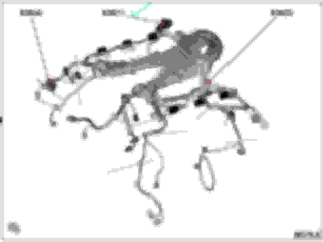
Okey, let me first visualize your wire harness. M276.9 and Left Hand Drive version.
So your Front SAM is at the LEFT of the car.
Find the X26 #1 first please.
Injectors 2 wires are direct from ECM, that is it.
So power to ECM is what we are focusing now, both +12V and the ground ones.
Below is the negative or ground input for ECM from W16/5. W16/5 is not on engine block. It will be on car metal body somewhere.
W11 is ground also for ECM and other components on the engine itself, and W11 is from engine block as the ground.
Now W16/5 as you know also supply negative or ground to Z6z2 splices which are for all the COP, assisted by another splice called Z6z1 and the connector source is X26.
That 4th brown-only 2.5mm wire on above image list goes to Z6z2 and Z6z1.
So for COP : From source to final end user
W16/5 eyelet >>>X26 connector>>>Z6z2 splice >>>Z6z1 splice. In theory , Z6z1 splice is the most distant away from W16/5 and that Z6z1 is feeding -12V or ground to COP 1, 2 and 3.
X26 male and female pin fitment and condition you must check. I believe they are also SLK2.8 if big one and if small one MLK 1.2.
ECM short connector 56 pins called F connector, you must also check its condition and pin fitment of the 3 female terminals SLK 2.8 as per photo above. Pin 2,4,6 for ground.
Pin 1,3 and 5 are all the same +12 power from fuse 25 via splice Z7/73z1 so you must also make sure this splice is good condition and ADD: the female terminal at connector pin fitment is also good.
4 wires in that splice, 3 to ECM of 1.5mm size and 1 to Front SAM of 2.5mm size all red-yellow.
West wrote :
Fuel Injector circuit since my #1 injector does show different voltage readings for total voltage and supply voltage. One I believe is what the computer sends to the injector to charge it and the charged voltage is what is used to open and close it. At idle my #1 was showing .72V on the low side and 172 on the high sidewhile the other injectors are showing .58 to .65 low and 156 to 161 high side. So #1 is off for some reason and 3 different injectors in that hole have read the same.
I did load test both injector wires to the computer connection and they both checked perfect. Did not start or touch the car today to see if it ran better. No need, something is wrong and keep showing up, it will till it is found and fixed.
Let me try to understand those numbers. The high value/side , not the low value/side one.
Lets assume Launch scanner have managed to take data out of ECM which Xentry is not showing. Could be development data or "hidden" sub-folder so to speak. Xentry also has development section we can't access .
Let's assume those injector voltage numbers are accurate.
Launch is reading at the ECM and not at the injectors, for that voltage. Let's imagine that Launch is reading voltage at is most upstream source.
In my understanding ( I am not good at all with electronics, electric I am decent ), if Launch read higher voltage at injector #1 .... that seems the injector #1 is not loading the circuit enough, compared to injector 2 and 3.
Not loading the circuit enough also means injector #1 did not work electrically as it should, less power consumed means less work. Hence that misfire....that is my theory.
The driver of the injectors is designed to power the injectors with power pulses at a set voltage and current. , not constant power.
If bad connection at terminals and wires to injectors exist, resistance goes up and current flow is reduced and injector get less power.
If we scope the injector voltage at the injector's male pin ( not female pin of the connector ), we read the true LOADED voltage and that will show LOWER voltage than other injectors.
BTW, I have to buy differential probe to scope the injector and do the scoping again, or else my scope will be damaged.
When you work with electric system, don't rush. We need to understand how the wires are actually routed or connected.
Certain schematic is very different than the actual as built for physical location of the splice.
In a schematic I can write the dot representing the splice to my convenient anywhere I like, but in actual wiring the splice must be at a strategic location as to be shortest possible to the device and actual ground stud or fuse source.
In a building , we call such real accurate electrical drawing as AS-BUILT drawing and not a simple SINGLE-LINE drawing.
Be patient and first understand the schematic./diagram.
Your post 161 is the exact same as my 2013 E350, M276.9 engine. I have not looked at that X26 yet but will today. When I had the wire harness open I looked hard at the W11 3 wire, single brown wire that is grounding 4 other brown wires. I almost replaced with a new larger wire but it tested fine loaded so I left it. Your wire schematics have helped very much since I still do not have a working WIS available. I will get back on it today. Thank You.
I think I found the W16/5, in this American Spec car there is a ground to body connection with two wires on the Passenger side, Right side of the car behind the headlights on the wheel housing. I had previously cleaned this connection, so the connection is perfect but maybe not the splices I have not yet found. The attached files should be deleted but it would not let me do that.
Last edited by Westlotorn; 06-13-2023 at 01:48 PM.
Does it match the expected wires: color and number from @S-Prihadi 's thread? Sure the loom goes along the wheel housing wall towards the back; however, I could not follow it w/o using a camera.
If I understand correctly, we expect W16/5 to be on the opposite side, but anything is possible.
I recall cleaning this one (just below the coolant reservoir) a few months (ground points cleaning effort for another issue) and it was a bit rusty (but nothing bad).
No idea yet, the left-hand drive cars have the brake booster and Sam on the driver side where Mr Prihadi says the W16/5 would be. Right hand drive cars have the battery box in this area? Some things get reversed. I can't imagine Mercedes putting an important ground behind the brake booster???
Edit: went back down tonight and started looking and testing again. Can not see the X16/5 connector looking down anywhere around the firewall near the brake booster.
Just for tests I set up my 3 light 5 amp load test and tested on several grounds to see what I might find. I made sure to use the exact same wire connections for each test. I had found previously that my test wires vary a little in MV ratings so I used the same for each test.
MV readings at variety of locations, All loaded with the 5 amp light load
Ground used for test
103 mv @ Body copper post ground near battery
103mv @ Body ground pass side behind headlights
103mv @ 2 valve cover ground locations X11?
117MV @ body grounds inside wheel wheel by Brake ABS system
135mv @ X26 Brown wire body side of harness female connector Gray color
150 mv @ Large Computer connector pin #3
153 mv @ small computer connector Pin #6
So there is voltage drop for sure in the computer grounds but is 50mv loaded a lot or a little and does it matter?
Thanks Mark
Last edited by Westlotorn; 06-14-2023 at 03:44 AM.
Does it match the expected wires: color and number from @S-Prihadi 's thread? Sure the loom goes along the wheel housing wall towards the back; however, I could not follow it w/o using a camera.
If I understand correctly, we expect W16/5 to be on the opposite side, but anything is possible.
I recall cleaning this one (just below the coolant reservoir) a few months (ground points cleaning effort for another issue) and it was a bit rusty (but nothing bad).
I think Cali is correct, W16/5 is near the brake booster for USA left hand drive and that is where my W16/5 is but me RHD has battery there. MB stated LEFT SIDE as description. But until you guys actually find it, we honestly won't know for sure.
Is there a way to test the ground? I know that this is an intermittent issue which doesn't seem like it would be a corroded ground post. I think the grounds should be measured with the harness being moved around.
I just typed this return and it seems to have vanished???? Dang computers or their operators can be a real pain at times. I traced grounds again and tested again tonight using my 3 light set up which gives me a 5 amp load No luck finding the X16/5 yet and I looked with a really good light. Ground tests looking for voltage drop. I used the exact same wires for each test to avoid variance. 117mv voltage drop at the body ground on left side/driver side fender by ABS system accessed through the fender skirt removal 103mv drop at the battery post on the fender top/ copper ground stud for jumping the battery 103mv @ both valve cover ground locations 103mv @ the ground stud behind the pass side headlight on lower fender 150mv @ #3 small Pin computer connector in the large connector 153 MV @ #6 large pin in the small computer connector 135mv @ X26 Brown wire in the gray female connector Largest Voltage drop is 50MV more than the best ground. Not sure 50mv loss under a 5 amp load is anything to worry about???
I tried to wiggle and squeeze the harness to make the connection go away, hard to do as every movement affects the pin connectors and aligator clips. Can't say I identified any iffy connections.
So if you start the engine cold is the misfire still there? I am wondering if it is a thermal related issue as in a circuit is opening due to getting hot. Would suggest that you drive the car again and assuming that it runs good when it is cold(?) drive it and remeasure it after it starts to misfire.
Do me a favor.
01. What is the part number of the original MB COP before you replaced them ? Are they all the same ?
02. Test continuity/resistance on BOTH of your MB COP and your current and new aftermarket COP, compare them.
COP installed on engine :
AA - Test pin 1 to engine block.
BB- Test pin 2 to engine block
COP removed from engine :
CC - The test is, between pin 1 and pin 2.
DD - Between pin 1 to copper ring and copper "needle".
EE. - Between pin 2 to copper ring and copper "needle".
Below is my COP, it shows what I mean by copper ring and needle
I been scoping my COP signals the whole day yesterday. I learnt a lot new surprises.
Simply put this way :
Pin 1 and Pin 2 of COP at the final end, both get connected to ground.
Pin 1 goes to W16/5 and Pin 2 goes to W11.
One of this 2 wires is a signalling or feedback wire , it tells the ECM that COP firing has occurred or not occurred.
As to why always Cylinder 1 has the misfire ?
I suspect it is because of the firing order where cylinder 1 is the first one on the firing order sequence, so its feedback is also the first one.
I worry your on-going misfire is not a COP sparking or actual firing issue, it is the signalling or feedback issue.
I will do a complete new post/thread on how my COP works and it may not be the exact 100% the same as yours,............. long story, maybe today or tomorrow I will make new post/thread.
Here is what EPC shows for M276 3.5NA COPs
I don't understand the one for the RIGHT side. Why its updated number is A276 906 01 60, which is LEFT side oldest number ?
Or that A276 906 05 01 is also the final update number for RIGHT side ?
List is too long, I am not showing all. What is important during my search for my own COP part number is :
My COP is specific to M276 3.0 Turbo and 3.5 Turbo only. Yes there are and quite rare M276 3.5 Turbo , in fact 6 of such engine variants.
So while looking at EPC for my COP , I thought of your COP too
I am behind answering this post. Sorry somehow some information was still being exchanged on the other 16/5 post. I decided my issue is not in the electrical and I have gone back and took the engine apart to investigate my #1 misfire. Pulled the intake, Fuel Lines, Injectors, High Pressure Fuel Pump, Valve Cover and removed the Exhaust Camshaft from bank 1. Studied the valves and rocker arms.
All looked fine on a quick exam, looked harder at the intake and exhaust valves. I was getting convinced that I might have a broken valve spring that was working well enough to pass a compression test but not a running engine?
What I found, one #1 valve was a little off center, not a lot but there is near zero clearance in this head design, it has to be straight. As I looked harder I found one valve Keeper is not there? The valve is currently held in place by one of the two needed keepers. Having only one valve keeper this one exhaust valve has been hitting the side of the head at the top of the valve travel. The spring shows signs it has been rubbing on the head in this same area. Again, there is no room around any of these valve springs. Maybe 1/16 clearance.
This same valve had a worn cam follower or rocker arm when I pulled the cam apart a couple months ago. I caught that and installed a new part but did not see the associated valve spring issue but I wondered why one worn rocker arm. Did not figure that out. Others look fine.
I did not wish to pull the entire head off and I do not have a custom Mercedes specific valve spring toool so I got creative. I have 3 or 4 valve spring compressors for other engines. I used a GM valve spring compressor for the LS engine design. Had to modify things to work but finally got it done. I ran rope into the cylinder, about 6’ of 3/8 cotton rope till I could not get any more in there. Had to use a 6” piece of 1/2” copper pipe to guide the rope down into the spark plug hole to install the rope. The rope works to keep the valve up in place while you remove the valve spring. Pack the rope in there and then move the piston up against it. Works easy and well. Had to hold the timing chain up and tight as I rotated since it was not connected to the cams. It took the whole afternoon but I did get the LS spring compressor to do the job, got two new valve spring keepers installed and now that bugger is dead straight in the hole just like the other valves in this head. I thought I would be pulling the cylinder head but now it is done. I plan to go ahead and put this back together and see if it will run on all 6 cylinders. Got the timing and cam installed, all marks dead on so far. I hope to fire it up tomorrow and see what I have. I have 50% confidence this was the issue all along. There is no doubt this car also had electrical demons and maybe still has them, the one ground that had a 1.2V drop was huge, that had to be causing issues but probably not the cause of my dead #1 cylinder. Mr.Prihadi I am certainly in your debt. When I get a chance I will go back and see what I can do for your needs. The Coils are removed at this time so I should be able to grab some readings. My memory says the coils hold a charge, as you start checking the voltage you will see the voltage drop from a high number and it keeps falling as you test. The coil power bleeds down.
Last edited by Westlotorn; 06-20-2023 at 10:54 AM.
 06-10-2023, 06:49 AM