When you click on links to various merchants on this site and make a purchase, this can result in this site earning a commission. Affiliate programs and affiliations include, but are not limited to, the eBay Partner Network.
While most owners pay attention to positive cable because it is visible leading to F32 PreFuse box, from battery +12V post, and the -12V ground wire most will know is only the one I am showing below :
The negative/ground post when cleaned
The 2 photos above only shows that the negative is connected to the car body, so our car is a negative ground chassis. Hence we call the car metal chassis as GROUND.
In a DC electrical panel, this would be called the negative BUS BAR, if in an AC electric panel single phase, it would be equal to the NEUTRAL BUS BAR and not EARTHING/GROUND Bus Bar.
This 1st connection from battery to metal chassis is only 1/2 of the story.
CONSUMERS :
01. The biggest consumer of power is the engine starter.
At peak current it can draw 570 ish amps ( 570 x 12V = 6.84 kilo watts ), on average after the peak inrush current it would be 200ish amps or 2.4Kw. This is a lot of current, but usage is short 2 ish seconds on a healthy engine.
02. 2nd biggest consumers are the electric cooling fan and the Electric Power Steering. They can draw up to 800 watts or 66 amps.
03. Engine management + headlight and all other DC electrical components, but not including electrical heater ( which my car doesn't have ), would be 15-40 amps region or up to 480 watts.
ABS if in action will take extra 20-30 amps.
Now, if engine starter is the biggest power sucker, how is the ground path delivered to the engine block ?
This one many people probably do not know, this cable is located in a kinda HOSTILE location, more so for those in countries with winter road salt.
This is based on my engine M276 3.0 Turbo and would be identical for M276 3.5NA or M278.
If I recalled, the grounding list document does not show this hostile located connection
See for yourself below ............ also attached as PDF
awesome isn't it. The most important ground wire for your engine is not shown on any document. Well, in my car, this is not the only ground connection not documented by MB
If there is a name I can use for this under the chassis SUPER IMPORTANT ground wire, probably I will be number as : W-TF
Since MB seems to use battery to car chassis a W10 as 1st point, this un-documented ground should be called W10/1
So Juan and Cali were discussing :
We have discussed the power suckers, now we discuss the power providers, which are :
01. Car main battery. Eco-Start-Stop baby 12Ah battery won't be discussed here.
02. The powerful 180 - 200Amps alternator.
Specific to the alternator, its body is negative path, hence only 1 wire , a big positive +12V from alternator direct to F32 prefuse box. No need ground wire.
Your battery stop being a primary power provider when and if the alternator starts pumping out voltage higher than battery voltage, the alternator is like a near sole power provider when it is at 13.8V.
The excess power output of alternator is then CONSUMED by the battery as charging power for battery. When you see your Instrument Cluster amperage + voltage reading, the minus - sign or positive + sign means,
that is what is pump out by the battery to assist alternator if a minus sign shown and what is taken in or consumed by the battery as charging current when + sign seen on the amperage data.
Now we shall discuss what I fear most if bad connection at the un-documented ground cable under the car to the starter, the W-TF or W10/1 .... LOL.
If this W-TF cable connection is bad/loose, not able to start your engine is your least worry.
Frying equipment or modules is the next possibility, because of alternative ground path.
I will give a simple example. The Electric Power Steering. It is a power sucker which is located so close to the engine, but it will never be allowed to use engine block as its ground.
Instead it get W2/1 or W2/2 ground point which is near the coolant bottle.
And the EPS motor is made as an isolated ground type, meaning it is not like an alternator where the metal body is the negative path aka ground.
Now, if the EPS motor is not isolated ground, when and if the ground cable W-TF has bad or loose connection or worse physically broken from corrossion, the much smaller W2/2 or W2/1 ground cable for EPS will
then be the alternate ground path for engine starter and guess what will happen to the wire or electronic control module of the EPS ? Well, sparky melt-down party will happen
There are many more hardware which can be negatively impacted if their small wiring is being used as alternative negative path for the starter motor during crank.
All sensors or perhaps COP ignition coil, which its body is the ground connection or has ground connection when attached to the metal of the engine block or chassis, as an example.
===========
Back feed will also happen if the W-TF cable broken from engine block. The engine block becomes +12V now if there is no alternate ground connection.
As illustrated by my ugly drawing below
Some good module design will have prevention of back-feed by using diode bla bla bla, but no one wants to experiment and verify that
If anyone wants to beef up or install a 2nd MAIN ground wire to engine, please do not connect it via the cylinder head, connect it to the engine block, alternator frame is a good place.
The reason is high current flow can cause magnetization of ferrous metal.
The camshaft can get magnetized and will cause ECM to go banana.
Here is an example , but at the crankshaft tone wheel region get over magnetized
I chose alternator as 2nd location to place a big fat 2nd ground cable is because alternator itself is a 180-200amps power provider.
MB chose to place 1st main ground wire the W-TF for engine is at the starter bolt, that is the biggest power sucker.
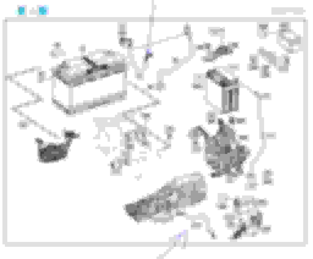
Here is my extra ground wires routing and sizes
The copper bus bar at the alternator for me to connect the 2 of 50mm soft welding wire :
Now 2 big wires at W10 battery ground post at suspension mount. One is original MB for battery to ground post. My 2nd new cable is at ground post to alternator.
I don't want the chassis to carry current for the 2nd ground wire, I use direct cable to the alternator.
I do not want to bypass the Hyundai battery sensor B95 at battery negative post, hence I use ground post at suspension mount as starting point of my 2nd ground wire.
Green color becomes original orange........
On the W166 additional ground wire, here is the diagram from EPC for the W166 (Electrical Equipment/Battery-Starter-Alternator Cable)
So, part 70 is the common wire from the battery negative to the ground jump post, and part 510 is the one I mentioned previously.
I will update you when I take a photo of the AC compressor and the wire together. If I recall correctly it is attached to the front mounting bolt of the AC compressor. The only reason I took it out was that I unbolted the AC compressor to gain access to the ECV w/o disconnecting the hoses.
I have not been able to find the main ground strap to the starter in the EPC. I may need to find the W166-W-TF cable as well
This (-12V) got me thinking about 24V like heavy trucks. In car DC circuits, the GND reference is at zero volts. There are really no negative voltages below zero.
In AC circuits, yes the voltage and currents spend half the time below the "neutral" reference at zero grounded to earth only at the braker pannel.
The thing we are missing is a little brother to strap #510. engine to chassis GND
The engine transmission ate always vibrating on their mount and moving significantly under torque. The GND strap brakes down physically and the exposed surfaces develop oxidation to create significant drop voltage.
The battery (sensor + GND) cable $144 is ok. We can not bypass the Hundai sensor. It's keeping tally on the battery status.
I liked the part about what happen when a module acts as replacement path for GND... yeah like ECU and F-SAM that are connected to engine & chassis. Spike that!
One of the enemy of good GND is "aluminum alloys"... oxidation is insulating. Steel and copper both have conductive oxides - So good to use to strap a long lasting GND. That alone will shave 20 to 30% of starter initial peak current on the already oxidized existing strap in rust belt (Pierre!).
A poor GND path is just as bad as a poor +12 power feed through a pin-head solderless contact. Lucky for us here: GND is GND. It's super important as the only reference to the whole car power source: ALT (BATT is only for starter).
GND path: ALT > Engine > Chassis
...more later...
Last edited by CaliBenzDriver; Mar 24, 2023 at 08:43 PM.
Cleaning ground connections seems like a good preventive maintenance.
Did you disconnect the battery first, or is that necessary at all since we are dealing with ground wires?
I disconnected both the positive and negative cable at battery for safety. Minimum you must disconnect battery positive cable .
I removed the battery out of the tray too, as there is another ground wire I can not ID and it is very near the bottom of the steel battery tray.
I think it belongs to HVAC cabin blower. Having a right hand drive car is very troublesome/frustrating when looking at wiring location indicators from MB, as it is for Left Hand Drive.
Ground cables are indeed important. An example of this is painted ground connections on 167 which have caused electrical problems for owners, particularly with the failed 48V EQ-system.
So, my ground wire number : W-TF is also in the part list , but not in wiring diagram.
I think Juan's W166 W-TF item 510 in drawing is the same W-TF as my W212 item 320.
So perhaps W166 also only has 1 wire from under chassis to the engine block close to starter. After all tranny bell housing mating to engine is where the starter motor is.
What I am trying to say is, don't take the whitish looking aluminum oxide layer lightly when you see it developed between engine block and your cable lug.
In my country, they use aluminum wires from electrical pole to home ( over the air wire ), if the dumb-azz technician does not use proper bi-metal lug ( aluminum-copper), long term the home owner will have
issue, as the bus bar or components in the electrical panel are copper compatible but not aluminum.
Bi-metal lug for alu cable : https://www.powermac.net.au/electric...bi-metal-lugs/ https://www.mgelectrica.com/bimetall...urable%20joint.
I learn of aluminum galvanic issues from yacht's captain & engineers operating aluminum yachts, but at that time I was not paying attention to the electrical side as these yachts still uses
copper cable. The technique of isolation for prevention of galvanic reaction between aluminum and other metals they have to apply on their sea water cooling piping system where the ball valves are stainless steel or marine bronze
on aluminum pipes are so delicate. Sea water is the electrolyte , that is the worry part. If all dry and no electrical semi-conducting liquid is involved, no issue.
My home in Bali is 800 meters away from the sea and the electric cable from the power provider is aluminum
Electrical issues at coastal properties in Bali is not un-common, at some months the strong wind send wet salty air to my property.
Every year, I get at least 3 times power problem, 2 of the 3 phases will be low at 60V or 120V ( If in USA its like 15V and 60V ) where my system is a 230V/400V 3 phase.
So in the single phase use I want to see 230V. A few electrical components at my Bali home got damaged from these very low voltage situation.
===============
While I could clean my mystery W-TF ground cable lug, it was only the lug for the chassis, I could not access the lug at the engine block near starter, its hard to access.
One day I need to un-do that lug and clean it. If there is any alu-oxide, that is where it will happen, not the one at the chassis which is copper lug to steel stud.
That why we want a secondary engine/chassis strap located high away from splash undercarriage area, preferably connected to steel and not aluminum.
======= smart home power:
In your Bali home with 3-phases AC Power: it's a great idea to measure the voltage between each phase to GND.
Make sure the same voltage range is present... not one leg is missing half its voltage .
Phase imbalance overheats 3-phase inductive loads... kills motors - Same is true with bad run caps in the 120VAC world: it helps kill home A/C compressors.
I have done quite a bid of hands-on with success. Not only you want to measure your start/run caps, you also want to use "a slow soft starter" to ramp up the start current instead of starting from a tall spike stalled-rotor current diwn to run-time current.
For A/C applications there are smart u-controlled starters that make system last for ever and decrease utility bill with zero surge: win-win!
3-Ph. is the way to go for heavy load to split power needs. We can use variable frequency controllers to ramp speed up/down automatically at each start/stop = low mechanical stress on rotor bearings = long life!
+++++ location location....
I was looking for a sight to host the additional GND strap, on driver-side opposite of existing...
then I recall looking at the way the ALT cable goes between engine/chassis... is that the engine side with the least engine motion in relation to bad mounts?? sight for bridging engine to chassis
Last edited by CaliBenzDriver; Mar 27, 2023 at 11:19 PM.
Sorry late reply Cali. Me out of country since 28th March. Just got back last nite.
Cali wrote :
+++++ location location....
I was looking for a sight to host the additional GND strap, on driver-side opposite of existing...
then I recall looking at the way the ALT cable goes between engine/chassis... is that the engine side with the least engine motion in relation to bad mounts??
On my engine, the big positive alternator cable come from rear of engine or firewall , source is F32.
From firewall to engine the "jump" point is at the middle of the engine and then it snaked a bit and connect to the alternator from under it.
My additional negative big wire ( orange ) as 2nd ground, it come from front of engine at the sub-frame. I added extra length to allow engine movement.
================
I once inspected my positive cable and the plastic spiral cable protector actually has water inside it . So I made a cut out for water to drain.
You see, the positive cable looped a bit from under alternator, so at the U bend ( loop ) it can collect water inside the plastic spiral cable protector.
I cleaned my positive cable lug and add 3M rubber splice tape and 3M 35 vinyl electrical to protect the crimp.
One thing I respect MB for : is the soldering at cable lug.
I forgot to add. I chosen welding wire as 2nd ground wire because it is the most flexible wire we can buy.
Its total copper strands are much higher numbers than ordinary wire.
Q. The flexible wires are larger than standard rigid stranded classes for the same wire gauge, so does that affect the capacity of the lugs?
A. Yes. Generally you will need to go up one size to be able to accommodate a flex wire of the same maximum gauge. Each lug rated for flex wire will have the maximum and minimum size (gauge) of wire that can be used. Look on the labeling that comes with the "FLEX" lugs to see what size range is available for flexible fine stranded wires and the respective torque to use on the wire binding screw for that wire.
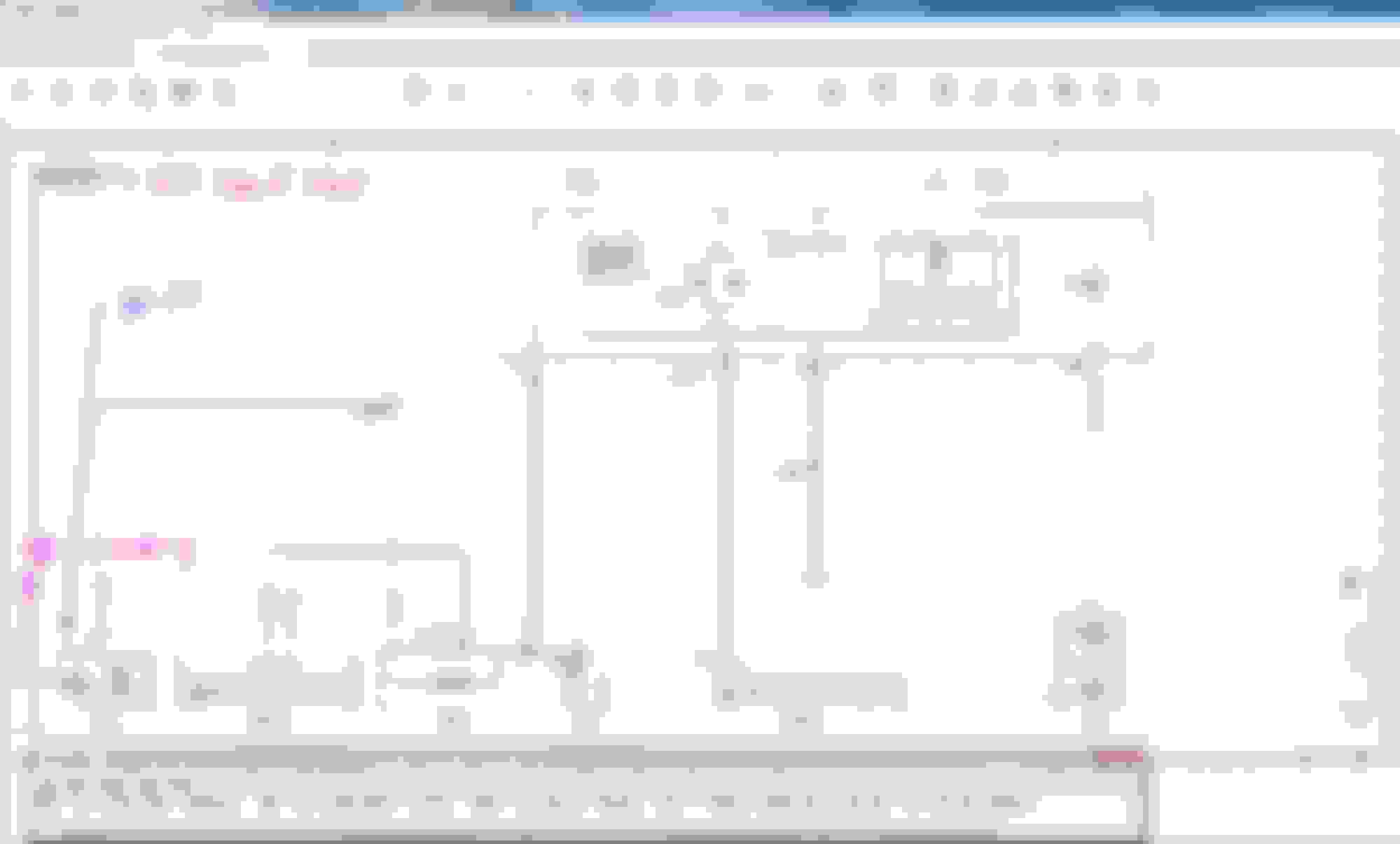
For the curious ones............ attached the wiring schematic. pe15.00-p-2101-97dag, Wiring diagram of starter, alternator, battery . Engine 157, 274, 276, 278 in model 212 (except 212.095) up to model year 2015
How in the world the mystery ground cable ( W-TF ) is not listed even in the starter system wiring schematic pe15.00-p-2101-97dag? : Well MB forgot . They also forgot to draw the Circuit 50, starter solenoid
B95 is Battery Sensor
.
.
Last edited by S-Prihadi; Apr 14, 2023 at 09:51 AM.
Reason: add info
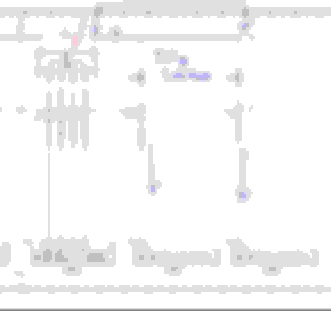
OK, I been itchy-handed today and never done a complete verification measurement with the extra ground wire, so today I did.
These are the amperage measurement points.
I am too lazy to measure at the MB's W-TF ground cable as I need to Quick-Jack my car.
So I measured at other points and re-calculate what MB's main ground cable W-TF will be carrying.
I use Xentry Compression Test feature where I can crank and crank and engine won't start.
This is cold engine at 30C. Before these measurements below, I have pre-lubed the engine by doing 3 times of 8 seconds Compression Test cranking. My battery is not fully charged by the time I conducted the test below.
I have corrected above drawing to represent actual cables quantity and routing for the 6 mm2 cables because previously I drew it wrong.
I also corrected the orange cable diameter, it is 35 mm2 SuperFlex, which is equal to 50 mm2 normal cable. Cable link is here : https://www.weldconnect.com.au/cigwe...lex-weld-cable
I wrote constant below, meaning :
The current ramp has passed its initial surge, which was approx 600 amps for 0.5 seconds.
Measurement point, in photo for Main
Summary :
01. MB's ground wire W-TF has shortest path to starter motor. My car is RHD, so battery at W10 main ground stud is at the left side engine bay. Starter is at the left side of the engine too. 136.9 amps.
02. 2nd ground wire 2.2 from W2 ground , is 2nd shortest path. W10 >> car chassis>>W2>>>alternator body>>>full size engine block>>>starter motor. 45.6 amps , NOTE :the 35 mm2 superflex also assisted by 2 x 6 mm2 extra cable.
03. 2nd ground wire 2.1 from W10 but using 35 mm2 superflex wire only, is the longest path and least conductor total area. W10>> 4 meters of 35 mm2 superflex >> Alternator body >>>full size engine block>>>starter motor. Only 20.8 amps. Total 203.3 amps.
=========================
will continue........................
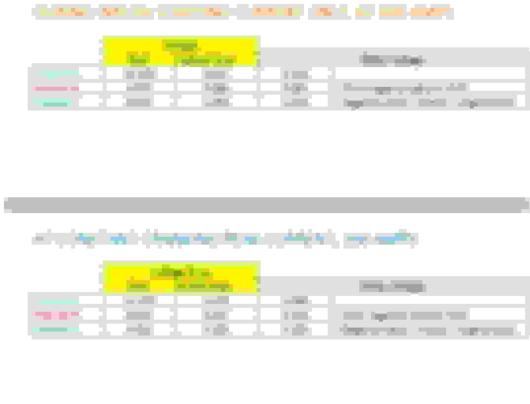
Now voltage drop test, albeit by battery is not fully charged, the result is still very good.
Channel A - Read battery voltage direct at its post, both negative and positive post. Channel B - Is the voltage drop between negative battery post to W10 grounding stud. This measures voltage drop by the B95 battery sensor and the approx 45cm main negative battery cable to W10 stud. Channel C - Is the voltage drop between negative battery post and engine's left side cylinder head where there is a lifting hook. Channel D - Is the amperage at MAIN negative wire from negative battery post to W10 ground stud. All grounds for A, B and C is direct at battery negative post.
The voltage drop values :
During constant cranking........
At initial starting , inrush starting current
SUMMARY :
01. Cranking inrush current using this super high resolution PicoScope exceeded my 600 amps current clamp. If using my Fluke with 20hz sampling, it would read 570 amps.
In 0.4 seconds later the constant cranking current is only 203 ish amps highest peak.
02. My battery is not fully charged and before I crank, the car computers are already consuming approx 14 amps and thus it made initial loaded battery voltage Channel A as 12.13 volts.
From the start of the crank to 3.8 milliseconds of 0.038 of a second, the battery voltage drop to 9.012 volt from the 600 amps inrush spike.
By 108 miiliseconds or 0.1 of a second, battery voltage recovered to 10.57 volts while discharge amperage at 352 amps.
By 0.433 seconds constant cranking hill/peak and valley/lowest amperage has occurred and voltage gets to be between 11.04 to 11.4 volts and discharge amperage by now is at 128 to 203 amps.
03. Channel B- Is the voltage drop between negative battery post to W10 grounding stud.
Highest voltage drop on this wire is at start of crank to 1.2 milliseconds or 0.001 second , where 0.66 volts drop occurred.
By 108 miiliseconds or 0.1 of a second, voltage drop improved to 0.30 volts.
04. Channel C - Is the voltage drop between negative battery post and engine's left side cylinder head where there is a lifting hook.
Highest voltage drop on this wire is at start of crank to 0.8 milliseconds or 0.001 second where 1.08 volts drop occurred.
By 108 miiliseconds or 0.1 of a second, voltage drop improved to 0.38 volts.
.
Last edited by S-Prihadi; Apr 16, 2023 at 02:22 PM.
Reason: Correction
Indeed Cali, if it become a sticky it woul help more members.
Since the oldest W212 is a 2009 model, 15 years of torture in winter salt for W-TF undocumented ground wire is a lot.
You will see more new members joining W212 section, as these cars are getting cheaper today.
The top issues for them will also include electricals, guaranteed.
Aside from corroding or loose ground wires.... Most of the constant ON relays in front SAM and rear SAM will be tired now if not soon, for high mileage cars.
The F32 K2 relay for Circuit 30g we been discussing ages ago, would be tired too...soon.
Next hot on the list will be 10 years or older cars with zero tranny oil + filter replacement up to current owner ownership.....and their tranny would have
issues. But this is not electrical, its a reality of neglect.
Surya, I still have not visited my PreFuse box
Didn't we say that our facelift K2 is a solid-state MOSFET junction, right??
(pre-facelift is a conventional relay with coil and contacts)
> Tranny 722.9Plus:
-- Fresh clean ATF is always best for all the internal bearings and screens.
-- Harsh shifts chew up the clutch packs frictions.
-- Best thing is seemless shifts from lag free throttle.
Early tranny care is cheaper than rebuild jobs.
Last edited by CaliBenzDriver; Jan 24, 2025 at 05:04 PM.
The confirmed one being electronic solid state relay is the V19 Q-diode for the start-stop operation at F32.
The K2 for circuit 30g is not confirmed yet as solid state relay.
..
.
V19 Q diode shown as "solid-state" relay for March 2013 upward model.
K2 shown as traditional mechanical relay.
From a 2021 case study :
Loose nut on B1 stud or positive battery connection to/at F32 , melting the connector plastic surrounding.
This is still with the LIN of alternator connected, thus F32 will send the crazy sudden high amperage charge to battery and load B1 wire.
During ECM killing charging to battery and then electric powered steering suking 80 amps, approx 120 amps will then flow from battery to this B1 bolt, heating it up.
In the case of our ALT-LIN disconnect, the B1 connection/stud handle very little amperage, because B1 backbone is the common fat copper bus bar with Alternator and K2 and
does not send or take much amperage from the battery itself, the alternator is the main power provider, thus it is local power traffic handled by the common bus bar and little of export-import at B1 stud.
Mercedes SLR McLaren 722 S Is Extremely Rare Example Modified by McLaren
Slideshow: A one-of-one U.S.-spec Mercedes-Benz SLR McLaren Roadster became even rarer after a factory-backed transformation at McLaren's headquarters.


 ), would be 15-40 amps region or up to 480 watts.


 . So I made a cut out for water to drain.