When you click on links to various merchants on this site and make a purchase, this can result in this site earning a commission. Affiliate programs and affiliations include, but are not limited to, the eBay Partner Network.
I measure wire voltage drop, not comparison voltage using 2 DMM.
A little over 0.2 volts drop at approx 7.1 amps
My COP stupid 0.5mm wires at pin 1, its voltage drop at 7.1 amps is so sad, 500 to 600+ millivolts.
B point also W16/5 hanging by the string .
A point also using 60 cm extension or test wire.
I have ordered special crimper locally, I will crimp and solder a new 1.5mm silicone wire.
The special extraction tool for SLK 2.8 ( without TPA ) and MLK 1.2 extract tool and 72 + 72 pcs of SLK 2.8 sealed and un-sealed...... I just ordered today from Germany.
In the next 30 days I think all will arrive and I can start to replace all 6 COPs pin 1 wire.
If anyone interested, here are the products :
01. Special crimp for the terminal we use :
alternative, get the PA-09 and PA-21 https://www.engineertools-jp.com/pa092021
I already have the PAD-11 but it is too small for SLK 2.8 and I ordered locally PA-21.
The 3 in 1 kit as per Amazon link I have ordered too from Japan heading to USA a friend's address, special zero shipping charge from Japan to USA and
that kit is so cheap at US$102 for 3 die sizes. My friend will carry home to Jakarta for probably July.
Wow, you are making me think my voltage drop is a non issue. Refresh me if you will, why are you testing yours? I thought you had a loose pin situation and already had it fixed? My current thoughts to make my 16/5 a stronger but safer ground without tearing the entire car apart. I have already accessed the 16.5 splice near the computer, why not just install a new wire from this splice direct to a body ground that I can access or maybe to the main body ground at the stud near the battery? I could back this up with another wire from the stud to the engine block just as an insurance policy to make sure all 3 are grounded.
Assuming your car runs on 6 cylinders with your readings my car should be in great shape but it is not at least as far as the wires are concerned. I will also state, every single place I go on this car someone has been there before me. Kind of tells me the prior owner had issues and a lot of work attempted to fix it.
Yes, great practical thinking with this shortcut to retire a known issue.
Temporary connect your W16/5 harness splice directly to a good chassis GND Post. Leave old W16/5 wire run in splice undisturbed good or bad, no problem. You're adding a parallel bypass.
The perfect GND candidate for US/LHD cars is behind our passenger-side battery... I recall seeing an unused optional "Painted GND Post" there. Clean it prior to using.
Make a temporary connection for testing... does not have to be pretty during tests, just a good Chassis GND.
> SHARED W16/5 :
-- Are the injectors GND using the W16/5 as well ?
-- I want to understand the shared use of W16/5 as only a low-power reference GND...
-- We do not want to mix any noisy "Power GND" circuit to a clean "Control GND" circuit. Need to be separated!
Last edited by CaliBenzDriver; Jun 14, 2023 at 06:35 PM.
Wow, you are making me think my voltage drop is a non issue. Refresh me if you will, why are you testing yours? I thought you had a loose pin situation and already had it fixed?.
Me itchy handed West
I never yet logged my voltage drop data on my COP and Injectors and power feed to ECM, so now at 9 years old, it is a good time for when I see decline as car grows older.
My car is easy to do, I do not have that big black engine cover which is PCV integrated and all the troublesome-ness of removing it from M276.9
M276.8 to access COP and injectors is sooooo easy.
> SHARED W16/5 :
-- Are the injectors GND using the W16/5 as well ?
-- I want to understand the shared use of W16/5 as only a low-power reference GND...
-- We do not want to mix any noisy "Power GND" circuit to a clean "Control GND" circuit. Need to be separated!
The ECM 2 wire output for injectors is like a floating power. No ground . Only High and Low wires (2) from ECM direct to Injectors.
Probably that is how they isolate the 200V from other components.
Below is my 3.0TT, but the same for 3.5 NA
This is why this scoping this injector is risky/bad for ECM if we use a common shared ground type oscilloscope. The M157 engine document also stated it. Same injectors type.
We discussed this in West M276 misfire thread
We like your hitchy hands fixing many issues on your W212-TT... a lot!
Should we look at the piezo-injector diagram as far as identifying GND circuits ?
The COP return coil-power through W11 and control-power to the GND post shared with ECU.
As soon as the ECU GND is repaired it should bring better performance stability to CAN Master. Even engine idle may start to sound different with less high pitched tic-tic and more like toc-tocs quieter injectors.
While working on power supply, disconnect the batteries -
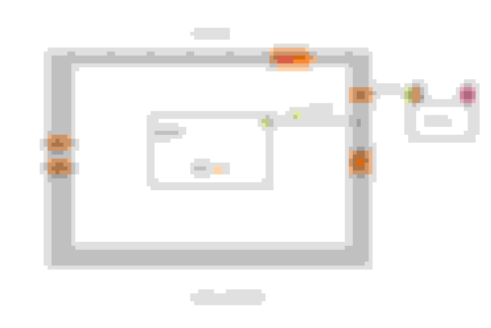
This is a simple but clear picture on how MB does its -12V aka Ground for Power and not noise control ground W11.
MB stick to the rule of STAR system.
Imagine that the whole car metal body is a Bus Bar, if in a home electrical panel AC system 110/220 60Hz or 230 50Hz countries, single phase.
So whole car metal body pictured in grey color is NEGATIVE Bus Bar, in a home it will be NEUTRAL Bus Bar.
So we have all except W11 as star connection. Sure, in the end W11 is physically connected to car metal or W16/5 or any of the star connection.
Battery negative>>>big wire to W10 which is car metal body.
W16/5 and all W2, W2/1 , W70 , W9 and all the Ws at car interior, are the STAR system.
W11 is I think best to call it as a Bonding point, if not ground noise control.
On yachts bonding has 1 extra advantage, that is to prevent galvanic corrossion on underwater metal components and its final destination is the sacrificial zinc anode under the water https://abycinc.org/blogpost/1839308...nt%20corrosion.
Bonding is also for lighting strike safety.
The COP.
COP pin 2 which is to W11 is also linked to COP small touch pin and the metal ring.
So even if you loose W11 wire to the COP, the COP pin 2 is already bonded/grounded to engine block.
Mercedes just want to be secure and added ground of W11 to pin 2 of COP.
I just measure it last nite. Good thing I keep photo of the COP in archive of 2021.
Just keep in mind, W11 is not for-12V power delivery.or true return path for the +12V power.
Last edited by S-Prihadi; Jun 15, 2023 at 12:54 AM.
Okey, I got my W16/5 stud on body as clean as it can get....finally.
My fingers can't fit into that tight space, my small wire brush can't fit there too.
So I deviced a DIY cleaner pad. Using size 13 socket, where that W16/5 nut is a size 10 socket.
I placed 3M green scouring pad as "sand-paper" on socket size 13 using electrical tape.
I then pushed the 3M green pad into the male stud of W16/5 and that 3M green pad will make its own hole...ha ha ha.
I then spin left right the cleaner pad manually as electric drill can't fit in that space.
WAS
NOW
The W16/5 wires lug/eyelet cleaned too, but can't be as shiny as the NUT and the MALE STUD at car body and I use brass brush on it as the 3M green pad will get stuck on eyelet protrusions.
This is a simple but clear picture on how MB does its Ground for Power and not noise control ground W11.
.....
The COP.
COP pin 2 which is to W11 is also linked to COP small touch pin and the metal ring.
So even if you loose W11 wire to the COP, the COP pin 2 is already bonded/grounded to engine block.
Mercedes just want to be secure and added ground of W11 to pin 2 of COP.
I just measure it last nite. Good thing I keep photo of the COP in archive of 2021.
Just keep in mind, W11 is not for-12V power delivery or true return path for the +12V power.
Damn... now I understand less than I thought I did an hour ago
We are dealing with the GND wiring of W16/5; W11; COP; ECU/Piezo.
Specifically the goal is to keep noisy spikes from COP & Piezo_Inj. away from sensors and low level ECU signals.
COP:
The tiny 0.5mm on COP is not a coil "power GND" with tall spikes. I understand it's a "signal GND reference" to trigger coils On/Off.... right?
Piezo_Injectors:
They are home-run straight to ECU with honestly sized twisted pairs.
I think the noisy circuits should stay GND to block W11 while the clean low-power should be on chassis GND.
What screw me up is my car COP wiring size.
The simple electrical fact. Positive and Negative feed to a DC device must be of equal wire size...PERIOD.
A single phase AC electric system, Live/Phase and Neutral conductor must be equal size, the grounding ( US speak ) or earthing ( UK/Europe speak ) has minimum recommended size but its is not as big as those 2 actual current conductors.
It is a closed loop. https://www.allaboutcircuits.com/tex...electron-flow/
If you measure current load at +cable or -negative cable, it will be 100% the same ( assuming no earth leak ), it is just the direction of how you clamp will show MINUS or POSITIVE reading.
Both wires are under the same stress.
So when I look at my COP, I readily assumed that the W11 is -negative power feed and W16/5 is the noise control or bonding wire so to speak, because the wire sizes chosen.
In reality when looking at M276 3.5 NA which is the wire for Pin #2 W16/5 or -12V is a good sized same size 1.5mm as its +12V pin #3 which is the PROPER wiring size
This is why I insist calling W16/5 as -12V Power as to not get confused with Ground as in Bonding use or noise control ground of the W11.
And then realizing MB is using star grounding system, that means W11 is not intended to be primary -12V supply, it is noise control, just like in M271.
M271 in fact uses capacitor to further reduce noise because its driver is in the ECM and not at COP.
Above is M271 3 wire COP, actually it is a 2 wire COP with 3rd additional wire as for noise control and that is the W11 duty.
This stupid 2 wire COP disguised as 3 wire COP really made me confused for a few days as I never mess with COP before.
See M271 capacitor C4 is between its W11 to Z7/35z2 which is the +12V supply for COP's pin #1.
The COP's pin #3 is the -12V power which is ALSO the trigger , because the driver is inside the ECM.
Z7/35z2 is direct from Front SAM fuse 24
Best to describe our COP as a 3+1 wire and not 4 wire COP.
===============
Modern Toyota uses a true 4 wire COP. the 4th wire is a signal confirmation of COP firing for the ECM, it is called IGF.
That pin 3 is the 4th wire IGF.
Now you would understand why I keep wanting to call W11 as noise control ground, otherwise many would mistaken it as true -12V power or return ground and failed to address W16/5 the REAL 100% true -12V/Ground workhorse.
I think only German cars uses double "ground" COP, be it 3 or 4 wires type, Bimmer and Audi and VW does the same.
I think why MB made specifically 3 inputs for +12V and -12V for ECM, below is my speculation :
ECM also connects to W11 , the noise control bonding wire. 31 in DIN speak is Return/Negative
The ECM has 3 zones or 3 separate duty/function in my speculation and the engineers wants to isolate them.
If I scope 5V sensors, I will use the sensor dedicated "ground" and not car chassis or engine block or battery negative, because I read some cars have filtered 5V system for sensors and that is the cleaner signal.
While in the end all -12V or ground will merge to battery negative post, we do not know what is the actual design inside the ECM.
My current thoughts to make my 16/5 a stronger but safer ground without tearing the entire car apart. 01.I have already accessed the 16.5 splice near the computer, why not just install a new wire from this splice direct to a body ground that I can access or maybe to the main body ground at the stud near the battery? 02.I could back this up with another wire from the stud to the engine block just as an insurance policy to make sure all 3 are grounded.
Assuming your car runs on 6 cylinders with your readings my car should be in great shape but it is not at least as far as the wires are concerned. 03.I will also state, every single place I go on this car someone has been there before me. Kind of tells me the prior owner had issues and a lot of work attempted to fix it.
01. Yes, you can do that and only to car metal body the W10 as you suggested and not any engine metal.
02. DONT, we do not want that new wire to fry your ECM when and if your un-named ground wire under the car body towards the starter motor bolt, which I call that wire as : W-TF get loose or bad contact.
03. Wow, that is a big problem as we do not know what could have been done wrong..
Now, when you shake-shake wires and get different voltage drop reading, aside from possibility female terminals weakening, the wire strands breaking or pin hole leak causing internal corrosion on the copper strand is a REAL issue and
I seen many such problems. Usually the BEND/CURVE/CORNER area of install and hot temperature area aside from friction rubbing.... is the high suspect region.
It will not be easy to locate such middle of wire run and internally the copper strands compromised.
If on a home power strip or cable extension set, usually the copper strand get broken at the most commonly twisted area, which is cable entry to the power strip body.
Or depending on the male plug design and wire routing of the user, that male plug is also one prone area of failure due to curve.bending of cable into male plug.
Some installation is best to use a 90 degrees bend male plug.
You know what I mean.
I did add a new ground from the body ground to the ground wire at the Computer and to the X26 connector. I think it was a waste of time but since it was all open I went ahead and did it. Almost have it back together so I can fire it up again but I am not optimistic since the load tests did not show much voltage drop. Would be nice to have tested things as I went along but could not with the car taken apart. Will report back after testing today.
What screw me up is my car COP wiring size.
The simple electrical fact. Positive and Negative feed to a DC device must be of equal wire size...PERIOD.
A single phase AC electric system, Live/Phase and Neutral conductor must be equal size, the grounding ( US speak ) or earthing ( UK/Europe speak ) has minimum recommended size but its is not as big as those 2 actual current conductors.
It is a closed loop. https://www.allaboutcircuits.com/tex...electron-flow/
If you measure current load at +cable or -negative cable, it will be 100% the same ( assuming no earth leak ), it is just the direction of how you clamp will show MINUS or POSITIVE reading.
Both wires are under the same stress.
So when I look at my COP, I readily assumed that the W11 is -negative power feed and W16/5 is the noise control or bonding wire so to speak, because the wire sizes chosen.
In reality when looking at M276 3.5 NA which is the wire for Pin #2 W16/5 or -12V is a good sized same size 1.5mm as its +12V pin #3 which is the PROPER wiring size
This is why I insist calling W16/5 as -12V Power as to not get confused with Ground as in Bonding use or noise control ground of the W11.
And then realizing MB is using star grounding system, that means W11 is not intended to be primary -12V supply, it is noise control, just like in M271.
M271 in fact uses capacitor to further reduce noise because its driver is in the ECM and not at COP.
Above is M271 3 wire COP, actually it is a 2 wire COP with 3rd additional wire as for noise control and that is the W11 duty.
This stupid 2 wire COP disguised as 3 wire COP really made me confused for a few days as I never mess with COP before.
See M271 capacitor C4 is between its W11 to Z7/35z2 which is the +12V supply for COP's pin #1.
The COP's pin #3 is the -12V power which is ALSO the trigger , because the driver is inside the ECM.
Z7/35z2 is direct from Front SAM fuse 24
Best to describe our COP as a 3+1 wire and not 4 wire COP.
===============
Modern Toyota uses a true 4 wire COP. the 4th wire is a signal confirmation of COP firing for the ECM, it is called IGF.
That pin 3 is the 4th wire IGF.
Now you would understand why I keep wanting to call W11 as noise control ground, otherwise many would mistaken it as true -12V power or return ground and failed to address W16/5 the REAL 100% true -12V/Ground workhorse.
I think only German cars uses double "ground" COP, be it 3 or 4 wires type, Bimmer and Audi and VW does the same.
Surya, I need to understand this whole W16/5 GND topic better.
I don't think we need to get confused with the 4-pin Toyota coil that's providing a feedback to ECU.
Our simple COP has :
POWER: W11.GND + 12V feeds coil
CTRL: Trigger by ECU
Mystery W16/5.GND...
That's the one in question
Our options to rework W16/5 GND Post is to split some of the existing wires separately
or leave W16/5 grouped as is
The ECU "Painted GND Post" needs usual cleaning plus flaten the troublesome eyelet pins.
If W16/5 ground mixed the piezo injectors return with the ECU... inbound noise guaranteed!
So additional COP noise may be drawn in by piezo noise
(I got to run out now)
Last edited by CaliBenzDriver; Jun 15, 2023 at 08:20 PM.
Fired it up today with the new spliced ground connections and again no joy. Same exact issues with #1 misfires. I wiggled the wires to no avail. Pulled the manifold again to start checking deeper. Unfortunately on the M276.9 engine you can't see much with the manifold installed. I did tighten up all the ground connections in the smaller connector at the PCM, ECM or computer connector.
Fired it up today with the new spliced ground connections and again no joy. Same exact issues with #1 misfires. I wiggled the wires to no avail. Pulled the manifold again to start checking deeper. Unfortunately on the M276.9 engine you can't see much with the manifold installed. I did tighten up all the ground connections in the smaller connector at the PCM, ECM or computer connector.
Not a good news
You basically have sorted out W11 and W16/5* ( *almost all ) related grounds.-
.
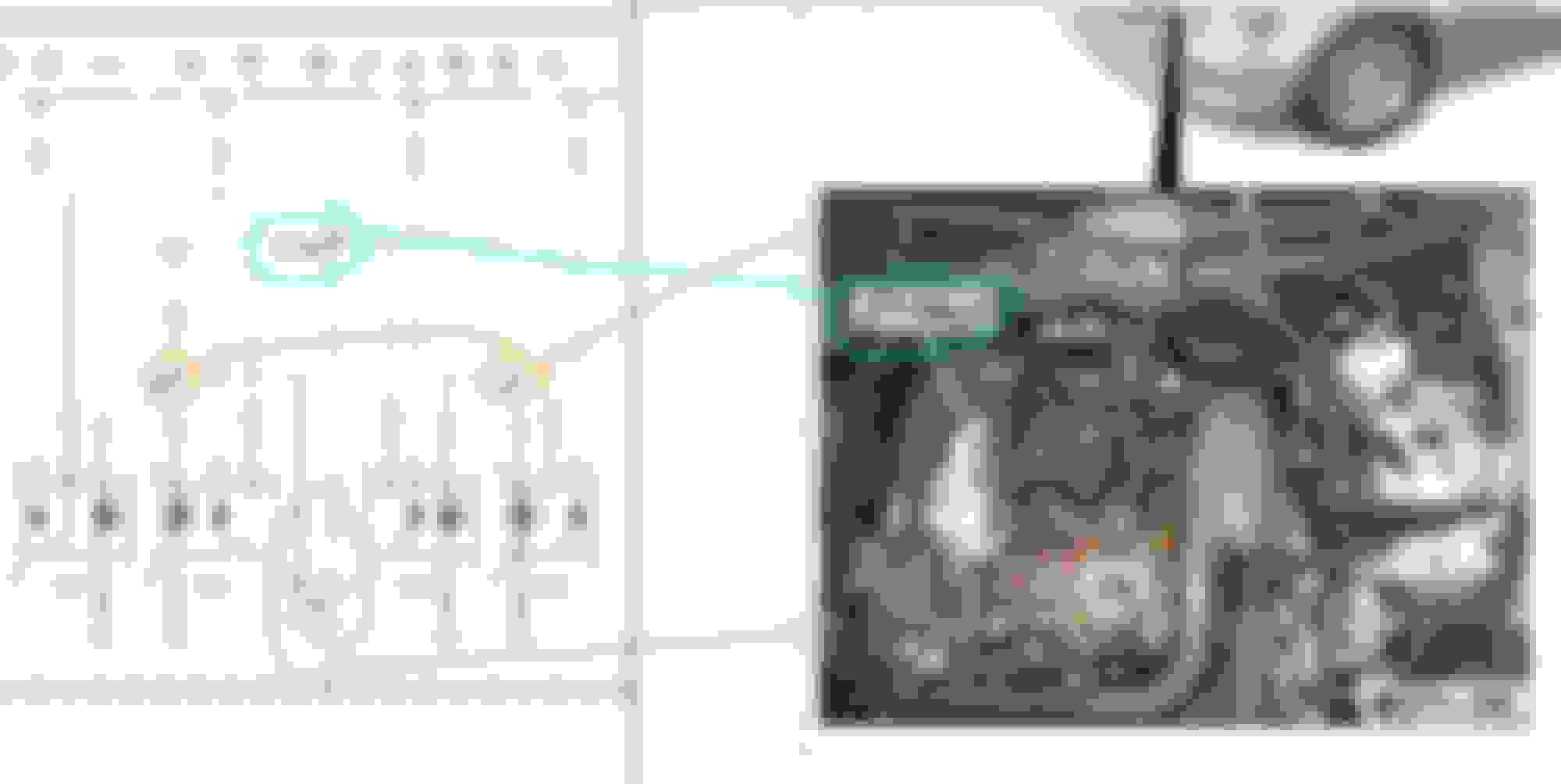
If you don't mind me asking :
Task number 6 : 153 MV @ #6 large pin in the small (F connector ) computer connector
Why only pin #6, how about pin# 4 and #2 ? These 3 are from W16/5 but all 3 are using individual wires which only get crimped together at the end, the W16/5 eyelet.
====================
I might have missed your post on injectors pin fitment and voltage drop test.
Your injectors pin number on the M connector is exactly the same as mine.
My M connector. I just tested pin fitment in detail today.
Note : My reference is brand new female MLK 1.2 terminals as VERY TIGHT.
From good to bad : Tight, medium, loose, loose-more and very loose
Weird, M50 is very loose but the voltage drop is not bad. I guess when load tested the male terminal sits well enough at the friction tongue, but when I do pin fitment test of 3 times insertion, I can feel the loose-ness.
Does MLK 1.2 MALE terminal get worn out ?
Not really, it is much much slower to feel loose when tested with new female versus new male and new female terminals feel.
Easily 100 insertions/mating is a non issue for the male, but not for the female one.
Too bad on M271 misfire case due loose female pin, I at that point in time do not yet have the correct male terminal to test, but that welding torch cleaner mini rods
at the least can provide comparison to the other female terminals on the ECM connector.
=============
Did you check F ( short ) connector big terminals pin 1, 3 and 5 pin fitment ? These are the power +12 from fuse 25.
Drop voltage test on these 3 is a bit tricky because of the front SAM is where you need to do the +12V injection.
Last edited by S-Prihadi; Jun 16, 2023 at 03:24 AM.
Once more, wow, a ton of information provided. Thanks for your efforts. Sounds like my engine should run great compared to yours based on the voltage drop comparisons.
I did check all 3 grounds at the m connector and they are the same. After adding the new grounds I have near zero voltage drop in my 5 amp test comparing all my grounds now.
I tightened my female connectors by taking a single strand of copper wire, my strand measured .025” right out of the wire strand. I took this round .025 strand and hit it with a hammer on flat steel. As you hit it you can see it widen, as it widens measure. For the large connectors I made this shim about .008 thick. It is easy to make it uniform by just watching how wide it is. Make it about 3” long so you have room to hold it and pound out about 1” at a time to make your shim. To keep the shim from falling out I bent a tiny part of the end into a J shape. Now I take the test connector male spade and use that to press the J shaped shim into the female slot. Press it fully in and then clip it off flush at the top. I took the connector with 3 shims installed like this and shook it upside down. They stay in place. The J hook seems to lock it in place. The shim is copper, should last many years. It was way too much work taking apart the pinned connectors to try an tighten them. I have to work a job today and probably will not get to this car again today.
Now
Last edited by Westlotorn; Jun 17, 2023 at 02:31 AM.
Once more, wow, a ton of information provided. Thanks for your efforts. Sounds like my engine should run great compared to yours based on the voltage drop comparisons.
I did check all 3 grounds at the m connector and they are the same. After adding the new grounds I have near zero voltage drop in my 5 amp test comparing all my grounds now.
I tightened my female connectors by taking a single strand of copper wire, my strand measured .025� right out of the wire strand. I took this round .025 strand and hit it with a hammer on flat steel. As you hit it you can see it widen, as it widens measure. For the large connectors I made this shim about .008 thick. It is easy to make it uniform by just watching how wide it is. Make it about 3� long so you have room to hold it and pound out about 1� at a time to make your shim. To keep the shim from falling out I bent a tiny part of the end into a J shape. Now I take the test connector male spade and use that to press the J shaped shim into the female slot. Press it fully in and then clip it off flush at the top. I took the connector with 3 shims installed like this and shook it upside down. They stay in place. The J hook seems to lock it in place. The shim is copper, should last many years. It was way too much work taking apart the pinned connectors to try an tighten them. I have to work a job today and probably will not get to this car again today.
Now
Dang, you and Cali has surgeon grade fingers/hands.
I can't handle something so thin and small
Dang, you and Cali has surgeon grade fingers/hands.
I can't handle something so thin and small
I am scared by those low-force female connectors... you make out with your patience to go after each these weak pins.
I can't imagine passing a few amps current through the tiny internal brush-fingers
Can someone with CHAT-GPT ask what is the best German-grade lubricant for electrical connectors.
I am interested to shield the oxygen away from oxidizing contacts
Last edited by CaliBenzDriver; Jun 17, 2023 at 04:45 AM.
On low voltage connectors, 5v and below I don't think you should use any dielectric grease. It does cause some voltage drop. Does not seem to bother the 12V connections.
On low voltage connectors, 5v and below I don't think you should use any dielectric grease. It does cause some voltage drop. Does not seem to bother the 12V connections.
Yes, true.
We want to protect oxidizing with a conducting coat of some long lasting heat-resistant goop.
You know about poor contacts of connector pins, right? Personally if I can help it, I'd rather prevent having to deal with this problem. Overheated toated pins, not good
It's exactly the sort of application need for salty marine use.
Deox is a well regarded product in the US but I am positive German chemical industry must have a whole family of effective products.
Last edited by CaliBenzDriver; Jun 18, 2023 at 06:41 PM.
I decided the electrical is fine and went back to the basics. Pulled the valve cover and trying to find what is unique about the #1 cylinder. Lot of work, yep, but I am thinking something is strange in this engine. I will certainly report back if I finally find an answer.
Mercedes SLR McLaren 722 S Is Extremely Rare Example Modified by McLaren
Slideshow: A one-of-one U.S.-spec Mercedes-Benz SLR McLaren Roadster became even rarer after a factory-backed transformation at McLaren's headquarters.