When you click on links to various merchants on this site and make a purchase, this can result in this site earning a commission. Affiliate programs and affiliations include, but are not limited to, the eBay Partner Network.
Thanks for the replies, I have ordered the connectors, am thinking they'll take 3+ days to get to me.
Re the AA and BB tests, I did some ohmmeter tests from the f25 receptacle (front SAM) earlier, pasted below...
<<< There are two connectors to the ECU, the one on the driver's side is marked F, passenger is M. With both connected insulation from the f25 fuse receptacle (side closest to engine) is between 0.7 and 1 ohm, this goes to open circuit when the F connector is unplugged, removing just the M connector has little effect. That value seems low given the fuse is only 15 A, so it looks like a hard failure downstream of the ECU or the ECU itself but probably unrelated to the devices that have been disconnected (they were discussed earlier, X26, etc). I'm assuming less than 1 ohm is bad, i.e. I'm seeing my hard failure.
>>>
Is this not saying the wires to the ECU are good (or freakily intermittent) and I'm either looking at a short in the ECU or the ECU is internally connecting f25 power to a downstream device that is shorted to ground? Doesn't this mean I can jump straight to DD? Am happy to do whichever tests you suggest.
I'm going to do some research on the refrigerant pressure sensor and rain sensor to see if their "failures" are somehow related.
Many thanks, it's not the basics of following wires but the hidden stuff (like where connector names are on diagrams and physically on the car) that are very helpful.
Oh oh.....I missed that post #13, sorry.
First let me verify something , because our Front SAM location is different, with my car being a Right Hand Drive and your is a Left Hand Drive.
Your Front SAM is located at the LEFT side of the car, mine is at the RIGHT side of the car.
Is your Front SAM orientation as seen from bumper to car windshield the same as mine ?
My fuse no 1 is at firewall side.
Since I do not know you Front SAM orientation with certainty, I will let you know the load side of the fuse, for my front SAM layout installed as a Right Hand Drive car.
This information from you : "There are two connectors to the ECU, the one on the drivers's side is marked F, passenger is M. With both connected insulation from the f25 fuse receptacle(side closest to engine) is between 0.7 and 1 ohm"
So for f25 fuse receptacle(side closest to engine) , are we talking of the same LOAD side ? ..... Position A of DMM test lead is the empty fuse F25 receptacle load side and position B test lead is the cylinder head metal ?
If your Front SAM fuse block installation orientation is the same as mine ( Fuse 1 at firewall ) but the front SAM plastic box is at the car LEFT side, that means your DMM test lead at fuse 25 receptacle if closest to engine,
it is at fuse input side or supply side, not at load side.
If we speak of the same load side of the fuse, cool
Now let me make sure I understand correctly the test you did, in blue. There are two connectors to the ECU, the one on the driver's side is marked F, passenger is M. With both connected insulation from the f25 fuse receptacle (side closest to engine) is between 0.7 and 1 ohm, My assumption for the test you did is, DMM test lead A (let say Red ) at empty fuse receptacle LOAD side and DMM test lead B(black) is to cylinder head metal.
I would call 0.7 to 1 ohm is a short but then again when the ECM is still connected by the connector F, it is not a guarantee.
I still prefer that you test zone by zone, since there are 3 total zones of suspect.
Front SAM wire harness to ECM which is F connector's wire harness, Zone 1
ECM itself, Zone 2.
Wire harness of connector's M, Zone 3.
Starting with least harmful test, starting with AA but revised to be more complete with Test DD combined. AA-Revised. Test connector F the 96 pins one . Test for short circuit of wire from connector 4i pin 10 to splice Z7/73 to ECM wire harness side F connector..... to ground or cylinder head. 1- Disconnect both connectors F and M of ECM. 2- Disconnect battery negative clamp. 3- Remove fuse 25 4- Use continuity first and then refine to Ohms when beeper sounds.
DMM lead positive(red) to Pin F-3 ( connector F pin 3 ) and later F-4, DMM lead negative(black) to cylinder head metal.
DMM test lead red to F-43, F-17, F-10, F-23 and F-11 . DMM black lead stay at cylinder head metal.
While doing step 4, shake-push-pull the wire harness which leads to the Front SAM. Resistance will be high for step 4 if any, would be few mega ohms if not OL ( out of limit ) or zero connection. If a near true short of say 0.7 Ohms, that would blow that 15 amps fuse. At 12.5 volts and 0.7 ohms = 17.9 amps load.
We skip Test BB for now, give ECM more love.
TEST CC - Connector M the 58 pin one
1- Disconnect both connector F and M of ECM.
2- Disconnect battery negative clamp.
3- Remove fuse 25
4- Use continuity first and then refine to Ohms when beeper sounds.
DMM test lead black to cylinder head at all times.
DMM test lead red (with help of MLK 1.2 male terminal as test probe ) , to each and every female terminal of M connector , marked with red circle.
Pin M-83, M-84, M-81, M-42, M-6, M-31, M-32, M-30, M-8, M-33, M-9, M-75, M-64, M-88, M-39, M-43, M-74 and M-45. Please re-verify all these are circled red, me eyes sometimes ****-eye hahahah.
No need to disconnect all sensors connected to above pin numbers, as none will ever be likely to read at under 1 ohm, unless its wire touched/short to ground.
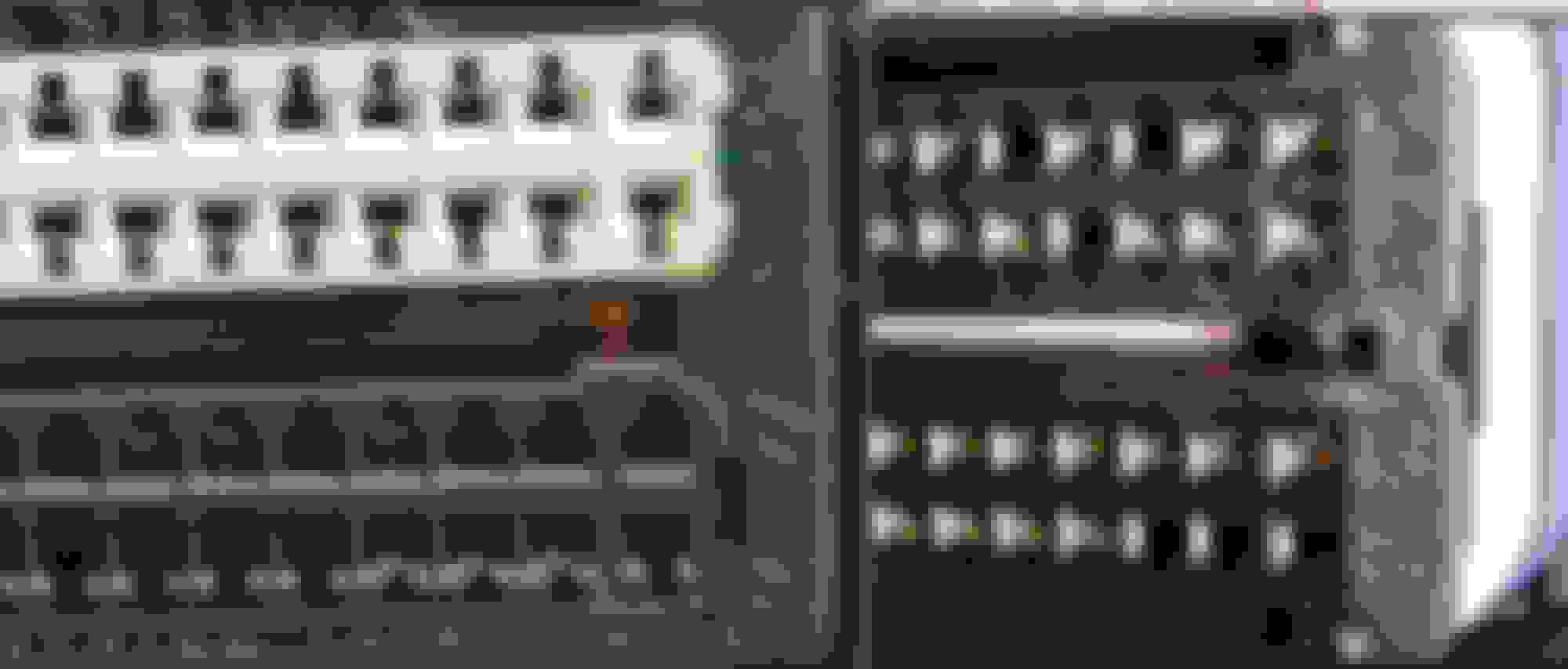
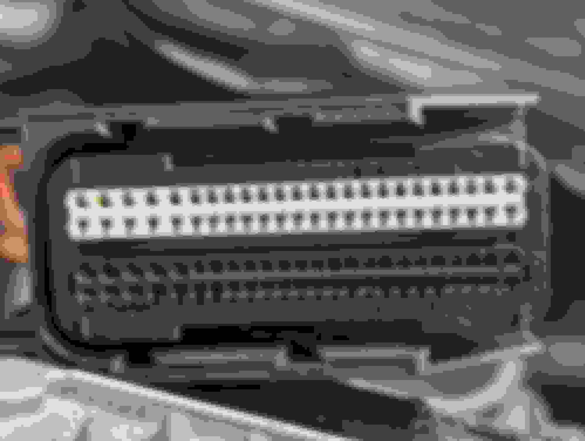
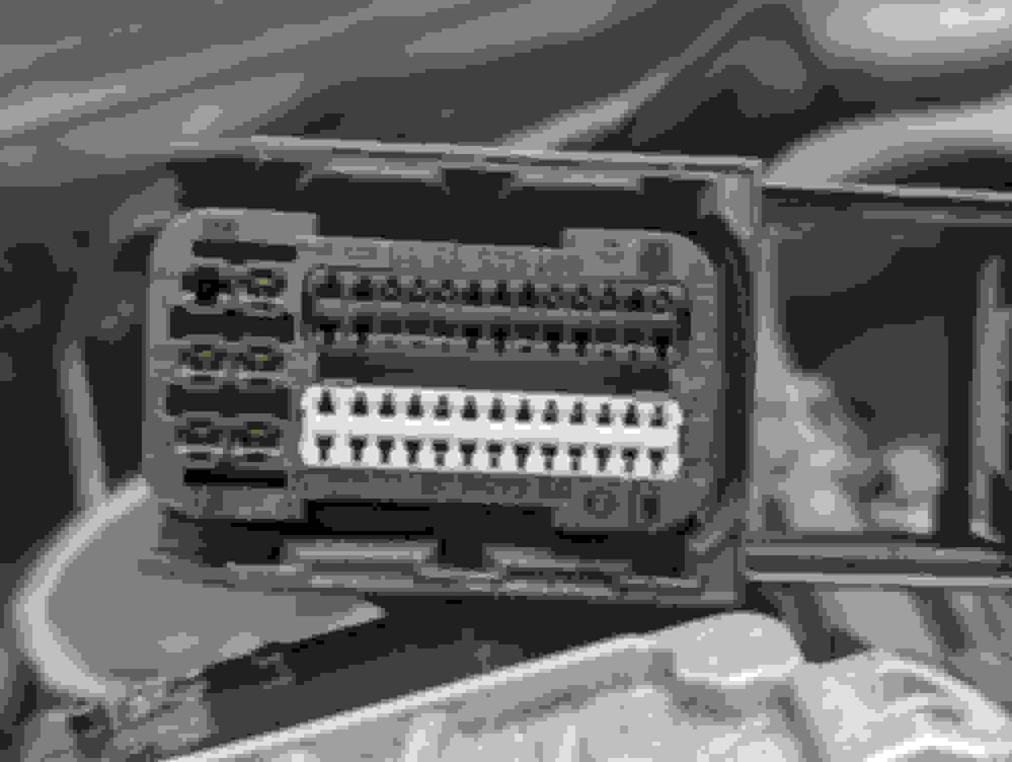
You ECM connectors you take a good photo and see if the number arrangement is the same as mine. If the same I can relate easier when later we speak of pin numbers on M or F connector.
Connector F
Connector M
From your initial test, it seems connector F wiring harness or a sensor or sensors could be the culprit.
I'll confirm later today but I think my front SAM is the same as yours but rotated 180 degrees, so the load side of the f25 receptacle is still on the side closest to the engine.
Furthermore, in post #22 I said i had accounted for all 80 terminals in the F connector, I've no idea where I got the number 80 from, in the vehicle wiring diagram for N3/10 the count goes to 58, that's the same as you show in the photo.
Here's where i got to without the SLK/MLK pins/sockets.
Re the orientation of the F SAM, pls see attached, as guessed above it looks like the same unit as in the RHS but rotated 180 degrees, so the output side of the fuse remains the side nearest to the engine.
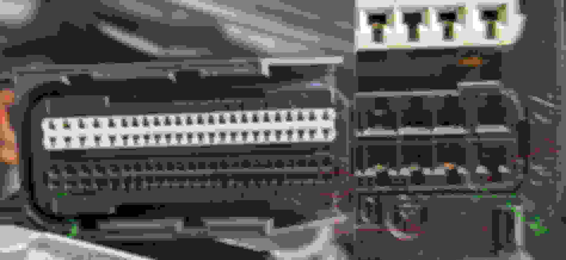
Pictures of the F and M connectors both at the ends of the harness and at the ECU are attached, no obvious damage, corrosion or oil.
Sweet, so Front SAM orientation for its fuse block now I know fuse #1 is to bumper, for Left Hand Drive.... thanks
Please take a look closer at your long 96 pin connector F, pin 96.
Magnifying glass is needed.
The female MLK terminal in pin 96 doesn't look right, pointer 1 in red. ( could be camera view angle, but please check )
Make sure the#96 female terminal is maximum inserted and there is no gap like all others and its square shape is not distorted.
Pointer 2 in red, someone been in this F connector, that looks like a screwdriver pry mark.
Pointer 3 in green, the black row ( pins 49 to 96 ) has more gap than white row ( pins 1 to 25 ).
When we see all this tell tale sign of someone been in there, we need to be extra cautious.
But M273 wiring diagram does not show pin 96 is in use Am I seeing blank hole shadow, but it does look yellow copper-ish
I have looked at the diagram 3 times
There are a few NC ( no connection information on the diagram ) as a mean to verify, one sample is shown below..... but MB sometimes make mistake too.
Highest number is pin 95 only, in use.
Why don't you do one by one visual check on the female F connector pins using zoomed photo, and go to wiring diagram to match/audit them one by one.
==============================
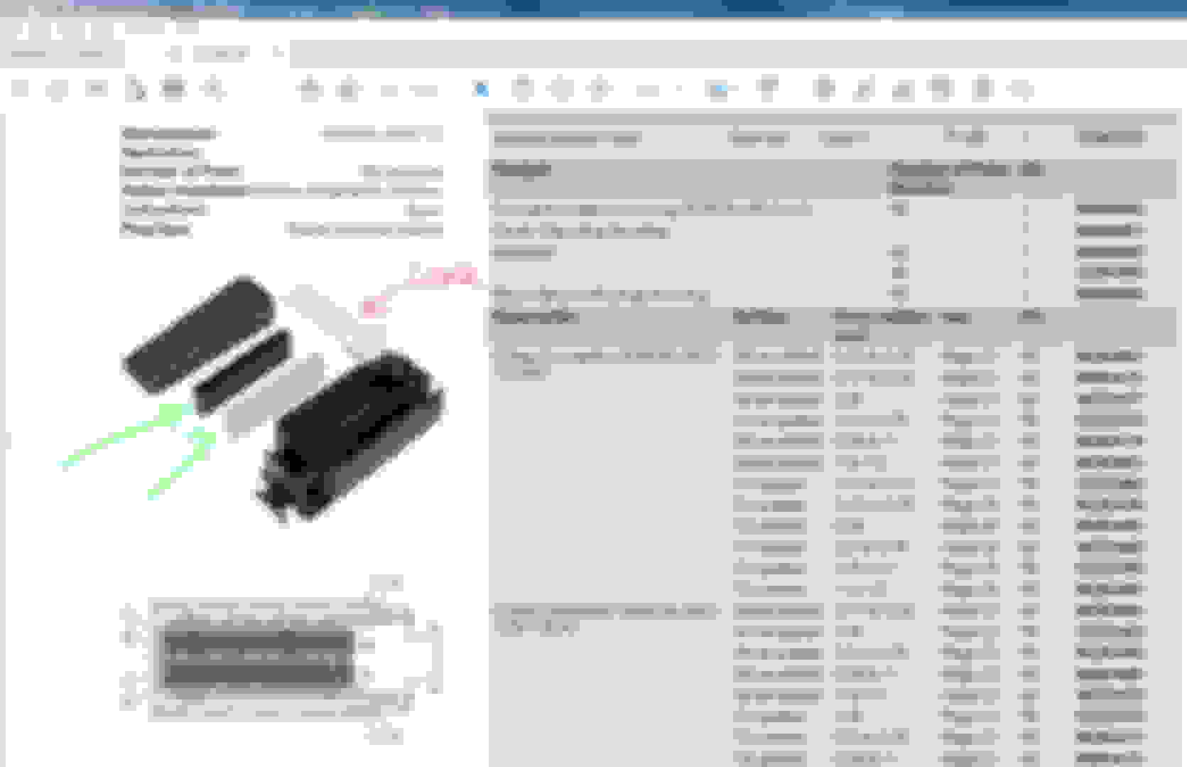
Now I see how the Kostal ECM connector have evolved for its design.
Your engine M273, M276 3.5 NA and M271 Turbo still get the replaceable insert for those pins bar white or black color, mine is not.
Kostal have improved dimensional accuracy for my connector by deciding to change to single piece design and on mine I can't change the insert pins bars ,
but the middle alignment groove been made smaller for less play. Its nice to see how the design evolved.
S-Prihadi and others who are still following this,
I can compare the documentation to the ECU plugs and check presence of sockets agrees with documentation, btw I did notice that your F plug has a socket in slot #1 while mine doesn't (which agrees with my documentation). I bought this car when it was less than 4 yrs old, I've no reason to think the ECU plugs have been removed, since then it hasn't been touched, nor has it been in to the shop.
I will put the ohmmeter on the load side of f25 (with ECU connected at F plug), wiggle wiring and see if there is intermittence.
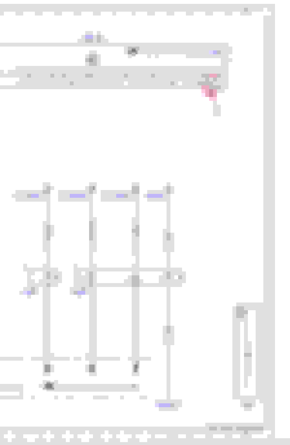
On document PE54.21-P-2106-97DAF I'll trace all load side wires of f25 to see if there's anything that could be causing an issue, but I feel the presence of the short only when the F plug at the ECU is connected is pretty damning. Without a diagram of the ECU it's impossible to see if there is an internal connection to failed device/harness issue on the same plug (I can check pin resistances to ground on the F plug when the pins/sockets arrive).
While waiting for pins and sockets to arrive to make test leads a couple of questions...
(i) Doesn't everything point to a failure of the ECU? Is the Xentry report saying it's alive?
(ii) Is there a reason not to open the ECU and do a visual inspection?
(i) looked through documentation, the other possible downstream connections for the f25 power are to other engine types, only the line going to connector 4I pin 10 is active, that's the one S-Prihadi flagged in the earlier replies.
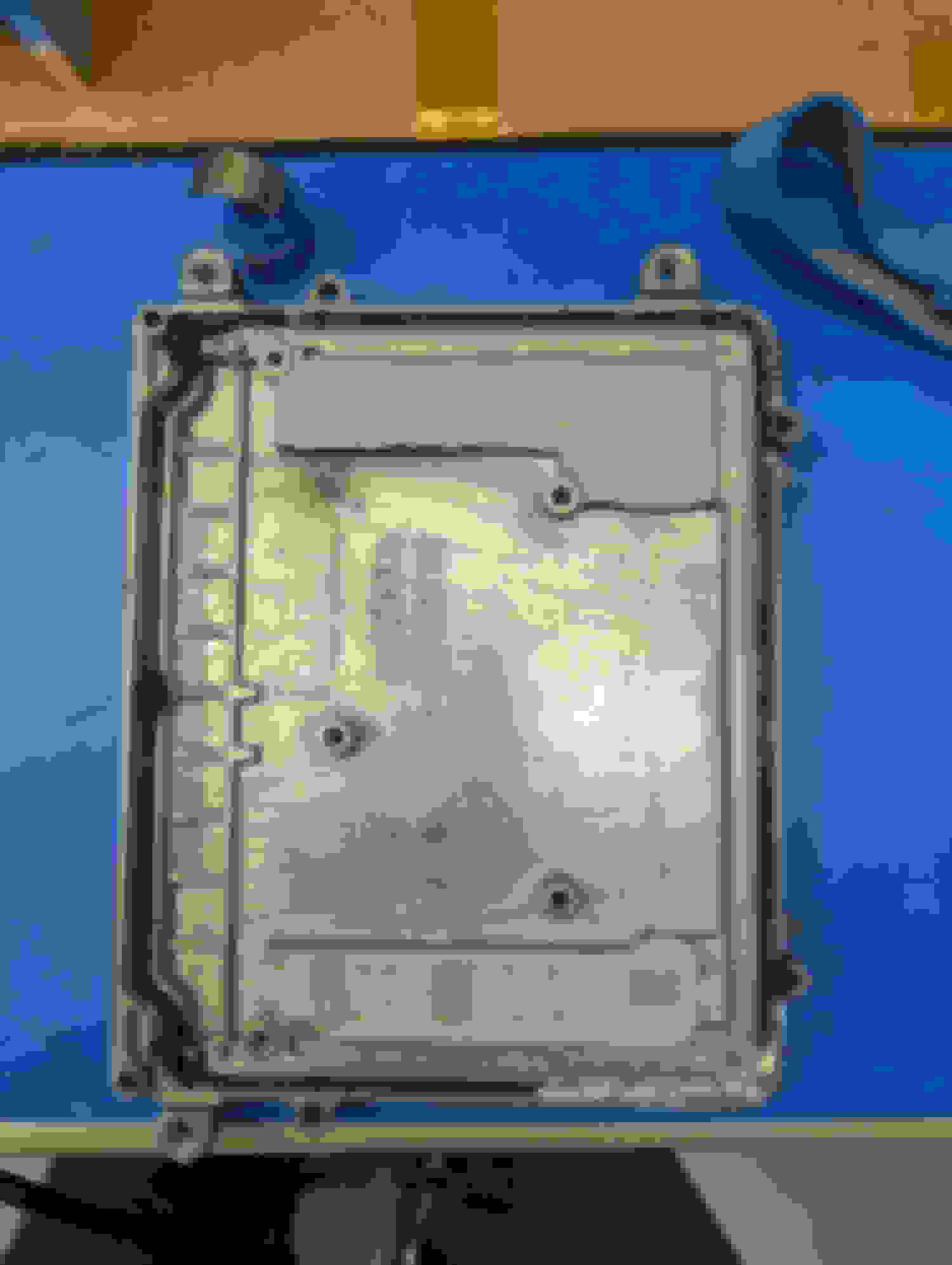
(ii) took a closer look at pin #96 on the M plug at the ECU, I agree there's a yellow shading, I've no idea why, I took the back cover off the plug and there's nothing there or junk trapped in the connector.
(iii) I attached a clip to pin #3 of the ECU and measured the resistance to ground, saw ~1.5 ohm, pin #5 showed the same, this agrees with the 0.8 ohms seen from f25 to ground.
For me this is pretty conclusive that there's an ECU problem, not to forget it might be caused by something else in the system. I removed the ECU and am attempting to pry it open, it's on tight, will make sure there are no other tricks to opening it up.
A big big thanks to everyone who has been part of this thread, at this point I'll see what's going on with the ECU and likely start a new thread.
(i) looked through documentation, the other possible downstream connections for the f25 power are to other engine types, only the line going to connector 4I pin 10 is active, that's the one S-Prihadi flagged in the earlier replies.
(ii) took a closer look at pin #96 on the M plug at the ECU, I agree there's a yellow shading, I've no idea why, I took the back cover off the plug and there's nothing there or junk trapped in the connector. (iii) I attached a clip to pin #3 of the ECU and measured the resistance to ground, saw ~1.5 ohm, pin #5 showed the same, this agrees with the 0.8 ohms seen from f25 to ground.
For me this is pretty conclusive that there's an ECU problem, not to forget it might be caused by something else in the system. I removed the ECU and am attempting to pry it open, it's on tight, will make sure there are no other tricks to opening it up.
A big big thanks to everyone who has been part of this thread, at this point I'll see what's going on with the ECU and likely start a new thread.
Peter
That is sad news.
If you got these : (iii) I attached a clip to pin #3 of the ECU and measured the resistance to ground, saw ~1.5 ohm, pin #5 showed the same,
while both connector F and M is not attached to the ECM, that is an odd value.
What I mean by ODD value is : My ECM metal cooling fin or its metal casing is not a ground. If I measure resistance from chassis ground to the ECM cooling fin,
the value will be a few kilo ohms while both F and M connector is still connected to it.
Well, our ECM model is different, I am using MED17.7 , yours is known as ME9.7 ( Xentry shows that data ) but the ECM actual full detail version I do not know.
Some ECM uses its metal chassis as ground.
ME9.7, In Spanish, but English translation works, how good the translation is I do not know...seems good enough.
So I checked, and yes I do indeed see 1.4 ohms from pins 3 and 5 to the case, BTW I also see ~ 1.4 ohms from 2, 4 and 6 to the case!!!, The meter reads ~ 0.2 when the wires are connected to each other. So I'm really scratching my head.
Opening the ECU was not easy, the goop used is very good, it's going to take some bending to get the sheet metal lid back into shape if this ever has to go back together. Looking inside everything looks perfect, the seals are all intact (no fluid entry), no discoloration, etc. I'll take a look under a scope later on. Will check out the ******* links.
My hope has been that I'd see some sort of 12V to lower voltage regulator with ugly burn marks and that I'd replace that and be done.
F connector Pin 2,4 and 6 are power ground from W16/5.
I wonder if your ECM metal case is actually grounded by design .... or something inside got cooked and ECM is actually not grounded type to its metal case....but the "jumped" happen.
0.2 ohms on DMM test leads shorted is normal.
I never tried opening any ECM yet, but I have an M271 ECM with defective ignition coil drivers, which I have always wanted to tear open but never got to do it, because I hate to un-do the gooey sealant used on the ECM.
So I checked, and yes I do indeed see 1.4 ohms from pins 3 and 5 to the case, BTW I also see ~ 1.4 ohms from 2, 4 and 6 to the case!!!, The meter reads ~ 0.2 when the wires are connected to each other. So I'm really scratching my head.
Opening the ECU was not easy, the goop used is very good, it's going to take some bending to get the sheet metal lid back into shape if this ever has to go back together. Looking inside everything looks perfect, the seals are all intact (no fluid entry), no discoloration, etc. I'll take a look under a scope later on. Will check out the ******* links.
My hope has been that I'd see some sort of 12V to lower voltage regulator with ugly burn marks and that I'd replace that and be done.
Peter
To trust a pass/fail decision on ECU VIP, you want trusted numbers, right?
Measure between the ECU pins involved with your F25 circuit. Resistance is always measured with all power removed because the DVM injects its own power to measure. (Do not measure Ohms in a partially powered/sleeping circuit!)
I think we calculated a 15A cutoff current would be a load equivalent to 0.86 Ohm, right...
So a 1.4 Ohm would work fine if indeed we decide to trust it's a valid resistance measure.
I use the word "trust" because it's super easy to measure invalid numbers for all of us without paying much attention.
IT'S LIKE... who do you trust with your front lug nuts.
HERE... the measurement is pretty much going to force a ressource commitment.
HALF FULL / HALF EMPTY:
If you'd found a low value from 0.1 to 1.0 Ohm, it would be conclusive but here with 1.4.... It's hanged on the fence in the grey area . Its doesn't scream bad and kinda "sounds good until proven bad" .
With that test being a hard evidence factor, the disconnected Throttle Body and Crank sensor do help point back at single consumer Mr. ECM.
Next post: failure analysis of this Bosch ECU. @S-Prihadi
Last edited by CaliBenzDriver; 06-28-2023 at 09:45 PM.
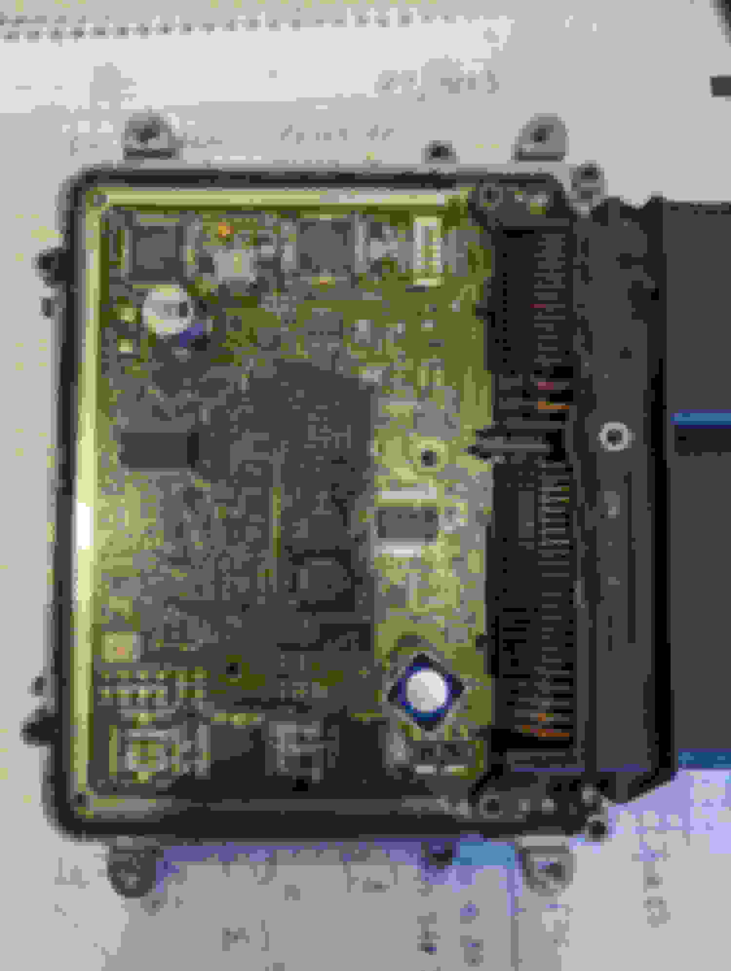
As noted above opening the ECU was difficult, really had to take my time and all but destroyed the sheet metal cover, only to find a board with no obvious issues. Furthermore, the PWA was recessed in, and well bonded to, the diecast heat sink. The bonding looked like thermal paste along with some of the elastomer used to seal around the connector, but that thermal paste was stiff like a non-rigid epoxy; in the photo of the top of the board it's the white stuff passing through the through holes. At this point my thinking was not being able to power the ECU meant cloning wasn't an option and so I was looking at either replacing chips with a donor ECU or opening my walled to Mercedes. Replacing chips would mean opening the donor ECU and that was never going to reseal in a way that I'd be confident in, so I'd probably be looking at a second cloning - not attractive. Despite the risks it made sense to cut the diecast and try to get the board out. I spoke to one of the cloning companies and they said they have removed the board to get the original ECU talking so they can download the information to copy to the clone.
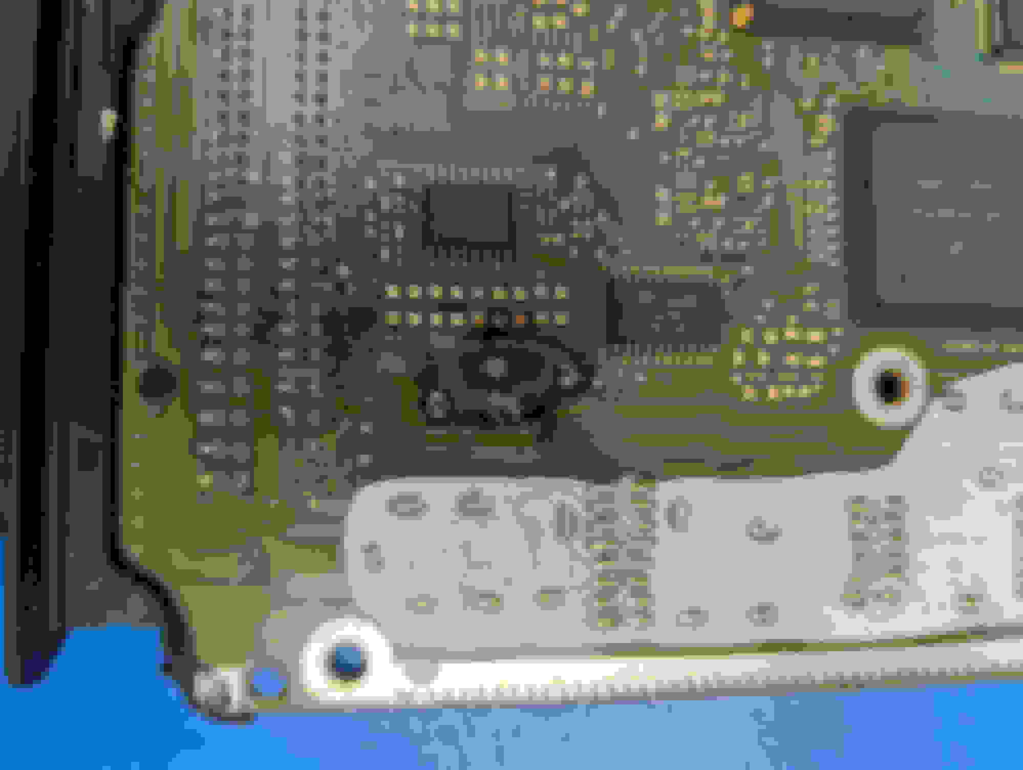
To remove the board I cut the lip off the diecast heatsink with a dremel and pryed the board starting at a corner, I did apply some heat but not sure it helped. The board came out easier than expected, yes you have to pry with way more force than you'd like to but there was never a risk of the board breaking. On the underside of the board the failure was obvious, see photo. The large capacitor with the square metal heat sink, see photo of top of board, had failed, this is known failure, it left a scorch mark on the inside of the diecast heatsink; so S. Prihadi it may well be that normally the ground is not connected to the ECU can.
After removing this capacitor, the resistance between the #3 and ground (pin #2, 4 or 6) on the F connector went up to ~3.5 ohms which sounds a lot more reasonable.
So I'm going to replace the capacitor, check the resistance from f25 and see if the fuse still blows, if all is good I'll see if Xentry can talk to the ECU. Fingers crossed that this will leave me with a system that can be cloned.
Again, big thanks for everyone's advice with this project.
this is great! You found ground-zero: the leaky cap shorting it's own shield.
I believe, I heard the trainer say that caps shorted to GND likely can not get repeared. Let me find the clip time .
Understand that capacitor is directly across the ECU power path. None of the undersized traces can support extreme heat stress...
Capacitor life performance are linked to:
environmentals (Temp, vibrations)
high noise ripples (need Low-ESR specs!)
unstable power
construction expertise
soldering wave duration
> Forward:
- Remove dead cap then power up the ECU board with a bench power supply at F25 inputs.
- The Point being you don't need a replacement filter cap now to test F25 blows or survives.
There are ecu replacement covers available...
TREAT THE TOPIC OF THERMALS WITH ATTENTION:
- Keep existing silicone, just apply additional thin layer of your favorite "white thermal compound" or "silver-arctic" before powering up for 12V testing.
When the ECU Temp sensors are not properly well connected to ECU heatsink, uncontrolled overheat can reduce life.
Last edited by CaliBenzDriver; 06-29-2023 at 01:49 AM.
This is a multilayer PCB board. Minimum 3 layers I guess.
The Spanish ME9.7 video have pointed out also the capacitors are top troublemakers.
If you are changing that blown CAP, might as well replaced the other soon to be bad CAP.
The engineer said if the leak is so bad and the corrossive liquid has entered the middle layer of this multilayer PCB, the PCB board is a total loss because the short there can't be fixed.
It is sad to see ECM being placed in engine bay.
Capacitor life being at 85C to 96C ambient temperature at engine bay for me while in traffic jam , imagine what is the working temperature of the capacitors ? https://www.xppower.com/resources/bl...at%2085%C2%B0C.
Until today I still can't find an elegant solution to cool my ECM with extra component assist.
My PC Corsair 1,000 watts power supply, its capacitor very much probably was no more healthy in about 7 years and the 5V and 3.3V supplies sometimes can't be stable and
end up my PC crash. Replaced new power supply, all good. My PC is never OFF almost, I keep it sleep mode too often. That 1st power supply life, 75% of it was in a
non air-conditioner room and that is 30C/86F minimum ambient temp, so it was in quite a hell.
My apology.
I ran a test again to be certain. My ECM metal case is indeed grounded. I was wondering what I was smokin' when I recalled seeing a few kilo ohms
My ECM physically is floating above cylinder head metal.
It uses 4 plastic stand 7 to 12cm long, so no contact of its metal case by touch to cylinder head.
So for what it is worth Westlotorn (misfire nightmare thread) bought another ECU for the car he was working on so there may be a spare available for purchase. Yours is a facelift car and the one he was working on was preface lift so that might make it a non starter.
My apology.
I ran a test again to be certain. My ECM metal case is indeed grounded. I was wondering what I was smokin' when I recalled seeing a few kilo ohms
My ECM physically is floating above cylinder head metal.
It uses 4 plastic stand 7 to 12cm long, so no contact of its metal case by touch to cylinder head.
ECU case GND:
Now you see why I mentioned earlier we always "sanity check" measurements - We get weird test results all day long, so we wonder why/how... before trusting results with actions.
We know have solid evidence the W212 hot ECU is subjects to capacitors likeage. Fixing that requires a extremely reliable replacement electronic.
These Bosch capacitors have to be "extended heat range" to survive a while but because the ECU is carefully located in the hottest place, ECU caps must fail.
It's like roasting marshmallows over slow fire....
The 3.5NA V6 has the ECU conveniently located by the engine side over the exhaust pipes.
A lot of electronics parts can handle severe heat including military tantalum caps (link!) but not garden variety parts. Finding an upgrade path is not simple.
We can learn the ECU failures points (caps and drivers) and learn to recognize them.
Basically all heat related!!
Lets try to provide something useful to w212 "care takers"...
symptoms
circuits
fuses
How: links!
..../....
Last edited by CaliBenzDriver; 06-29-2023 at 12:42 PM.
It seems I can find a used, as-is, zero warranty unit for ~$200 and with 30 day warranty ~$350 - am I feeling lucky?
I will connect the F plug and verify Xentry is able to read the ECU, if good will purchase replacement.
If it was easy to open the ECU I'd be tempted to replace the capacitors on a replacement, having the cover gets you a long way there (BTW CaliBenzDriver - do you have a reference to ECU covers? ) but you're still left needing to pull the board to unsolder the cap and that doesn't seem like something you want to do for a part you're going to be relying on.
A (dumb) capacitor question - given that the cap that has blown appears to sit directly across the 12V feed could the load on the device inside the ECU not be assisted with an external capacitor? Recognizing that any added capacitance would need to be physically close to the ECU.
It seems I can find a used, as-is, zero warranty unit for ~$200 and with 30 day warranty ~$350 - am I feeling lucky?
I will connect the F plug and verify Xentry is able to read the ECU, if good will purchase replacement.
If it was easy to open the ECU I'd be tempted to replace the capacitors on a replacement, having the cover gets you a long way there (BTW CaliBenzDriver - do you have a reference to ECU covers? ) but you're still left needing to pull the board to unsolder the cap and that doesn't seem like something you want to do for a part you're going to be relying on.
A (dumb) capacitor question - given that the cap that has blown appears to sit directly across the 12V feed could the load on the device inside the ECU not be assisted with an external capacitor?
Recognizing that any added capacitance would need to be physically close to the ECU.
Peter
Uncle Peter, I like your clean-cut problem solving.
Charcoaled PCB 😳
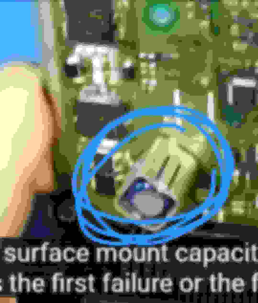
> Picture: notice the red and blue circles...
- The blue circle is blacked out all around one of the capacitor melted solder.... super-heated black!
- The red circle is the cap outline that includes both (+/-) pins inside the circle. Not bad.
- The two other nearby solders are the passive metal shield itself. Not bad.
--This means one of the blackened traces feeding the pin is likely compromised
-- Try it anyway, see if the short is still there or not then decide to chance it or not.
The way your ECU circuit board looks, it's not worth putting new parts on it.... it's history as noted in Spanish video. The epoxy mixed in with fiberglass with multiple layers of etched copper traces can waste into charcoal given extreme heat.
Short term: bush-fix capacitor to be tested
Long term: you do need a reworked ECU swap.
> Fixed better than new:
Send both donor/original ECU out to rework all new caps plus programming from your old ECU reading data or desoldering serial memory chip.
Ask for before/after pics showing your board ID's.
If there is one thing that I am glad is they did solder everything properly, no solderless lotery inside this particular ECU.
> Cap killer protection:
Now we have seen how overheated caps leak electrolytes inside conveniently unprotected via-drillings that then start an amazing 15Amps short-circuit charcoal between traces - - Bosch loves this but we don't!
- Caps work by ironing out riples: less riples, less work, less heat.
- Caps don't like voltage swings from failed voltage mgt.
- Adding external cap will help iron riples. This is what's done with the light duty "AUX batt" turned Farad Caps... these caps don't last too good. External caps would require testing to make sure we don't create a fire hazard to fix troubled ECU.
.../...
Last edited by CaliBenzDriver; 06-29-2023 at 08:50 PM.
To check we're on the same page, the external cap is not to somehow revive my FUBAR unit, I'm thinking of how to avoid the same issues on a replacement ECU.
Well, reading the ECU did not go well. I am now looking at option B which is to replace the chips with the identify information from my ECU onto a first donor - does anyone know which chips that is? Depending how much damage was done opening the first donor then maybe transfer again to an unopened second donor. I can get the fine soldering done.
To check we're on the same page, the external cap is not to somehow revive my FUBAR unit, I'm thinking of how to avoid the same issues on a replacement ECU.
Peter
Yes, I am with you about undoing the chaos out of this car! So far we've met some successes with more to come. The opportunities that are planted by designers gradually degrade the performance of their host. After a while things progress with warnings then complete failure. Make failures happen gently in a guided way, requires the "best in the world" German expertise.
I can say WE want to protect these hardworking ECU. They are some of the very best automotive chip architecture mixed with couple time-bombs to warrant business.
3-Nuggets against MB chaos:
Fix these in the following order
-- 1st discovery belongs to our master @S-Prihadi : the Painted GND posts. This creates power surges as the crappy poor connections become more oxidized.
-- 2nd discovery is the "solderless pins". (Fix your SCM/EIS as soon as convenient!!). - This generates glitches over the power pins and CAN buses. It generates soft crash that bottleneck with amazing software cooperation. Queues overflows are ignored: how convenient! SAM's + ECU require simple REBOOTS against that madness.
-- 3rd discovery is crazy voltage yoyo swings. That's a rudiculous under cover killer for the hot caps and both batteries. ECU gone wild... simply unplug ALT LIN.
Every car comes with a different set of options and related crafted chaos. As modules beging to interact and disfunction... you experience may vary, right Some cars hit 150KMi with just oil, gas and brakes - Sure !
> Now for the flip side: not bad...
It's better to engineer parts retirement in a gentle way than get complete random failures... (Limp-Mode in rush hour traffic 🤙
- When Bosh thinks your modules needs to go gently, I want to hope its to protect you from what would have been around the corner.
Imagine a catastrophic fuel pump failure, electric steering, TCU conductor plate...
- Think of it as a $3k "dealer wallet byte" vs. Hospital Emergency troma center....
> Open enrollment now:
Join the gang of MB grumblings hunters at MBWorld forum. We help one another make these tic well
If i dont develop the details everything is lost and most people don't get it.... that's why we are a friendly team aiming gentle efforts against non-sense.
++++ Why caps do get hot: R for resistor!
A capacitor is equivalent to a power tank with an inline resistor.
Thw older cap gets the higher redidtir goes
The more riples there are to ride up and down, the hoter gets the internal equivalent resistor.
> How to win:
- Lower Equivalent Serial Resistor ie. "Low ESR" caps
- Less riples, less work, less heat.
.... more capacitor: more heat!!!!
Now you know why we don't simply add more caps here right near the ALTernator with infinite ability to dish out killer voltage and current spikes because of very low R.
Don't fight with crazy ALT yoyo, manage it properly.
✌️
Last edited by CaliBenzDriver; 06-30-2023 at 02:59 AM.
Reason: crafted chaos is sweet
We know the ECM goes bang, aka kapoot.
But one should not assume that this is purely ECM aging capacitor. You still need to inspect as planned all the possibilities of any load side wires to sensors/devices if they do have a mild short
circuit to ground or not ...which can accelerate ECM electrical overload.
ECM consumes power to run its logic boards and also drive sensors and devices, among them are the injectors which are directly powered & triggered by the ECM
So, to be safe you still need to carry out the planned test/inspection on them wires/sensors/devices for the longevity of the soon to be replacement ECM.
 06-26-2023, 10:45 AM


 Am I seeing blank hole shadow, but it does look yellow copper-ish