When you click on links to various merchants on this site and make a purchase, this can result in this site earning a commission. Affiliate programs and affiliations include, but are not limited to, the eBay Partner Network.
Could be the sensor, but I have a growing suspicion there's an ECU issue. With the crankshaft sensor disconnected, as well as left camshaft exhaust hall sensor (B6/6), I read no conductivity between the two corresponding signal pins (#59 and #83) on the ECU connector. However, with the ECU connected, I read ~1Ohm, or basically a short between the two leads. As the wires are not connected to the sensors, this must be an ECU issue. Comparing this to any of the signal pins of the other camshaft hall sensors, I see no conductivity in those cases.
Meanwhile waiting for a return call from the company that did work on the ECU to find out more. I already spoke to them yesterday, but as their serial number label missing on the ECU they have a bit of a hard time tracking the history. But the logical next step would probably be to have them test the ECU once more, as there is no logical reason, at least to me, why the ECU would bridge these 2 signal pins.
yes, this totally makes sense: The hot exhaust cam sensor sent oil in the ECU that's now shorting with the nearby crank input.
Sounds like ECU did not get properly repaired or tested during service - This is not an easy job at any rate.
++++
It's too bad the ECU connector pins are not sealed to prevent external contamination.
I was just thinking about painting a layer of high-temp PCB protection at the base of input pins... but then my left brain said "If it works, don't f*** with it!". I don't have the urge to temper with that particular VIP box
I rationalized that with little chance of oil coming up my harness then no need protection...
The cam PCB pins laying near the crank pins provide a well executed failure. Crankshaft signal drives the whole engine timing calculations
Last edited by CaliBenzDriver; Oct 13, 2023 at 04:03 PM.
yes, this totally makes sense: The hot exhaust cam sensor sent oil in the ECU that's now shorting with the nearby crank input.
Sounds like ECU did not get properly repaired or tested during service - This is not an easy job at any rate.
++++
It's too bad the ECU connector pins are not sealed to prevent external contamination.
I was just thinking about painting a layer of high-temp PCB protection at the base of input pins... but then my left brain said "If it works, don't f*** with it!". I don't have the urge to temper with that particular VIP box
I rationalized that with little chance of oil coming up my harness then no need protection...
The cam PCB pins laying near the crank pins provide a well executed failure. Crankshaft signal drives the whole engine timing calculations
The magnet sensors on mine have thick gooey glue like substance sealing the pins negating the need for pigtails, the sealant is still soft but not sticky. I had put dielectric grease around the pins of my ECU to somewhat seal those in the same fashion even though no real signs of oil there. but from what I've read, it's not so much of oil in the ECU, but once ECU connector is flooded with oil, it wicks through other wires to other components, most noted were the oxygen sensors taking them out. But the same, I'm certain, could take place with the crank sensor.
I wish I knew what the sealer was, I would seal every sensor that touched oil, coolant, or trans fluid on my car.
However, due to heat on the crank sensor from it's location, several earlier model engines are recommended replacing crank sensor as a preventive maintenance much like the cam and magnet sensors on the later engines.
Here is measurement for you, of the CRANKshaft pos sensor
My tester wire kit number 1, 2 & 3 is the exact same as device/sensor connector number 1, 2 and 3
As I wrote on last post : I modify a bit
==================UNLOADED TEST ================================= 01. Do not connect connector M the 96 pins one to ECM. 02. Only connect the F connector, the 58 or 56 pin one to ECM.
With ignition ON, engine OFF, read pin 44(-) and 19 (+) at ECM male terminal, connector M.
================================================== ================
You can also do loaded test by not disconnecting connector M of wire harness to ECM.
UNLOADED TEST
If connector M wire harness side is removed, and you get say 5.5V or higher at pin 44(-) and 19 (+) at ECM male terminal, that is most likely issue with ECM.
Often ECM can loose its 5V power supply/driver. However you case is unique, the Exhaust CAMshaft Pos Sensor signal contaminating CRANK-Pos-Sensor.
I do not know if our MED177 ECM uses single 5V power supply or more than 1 channel. Some ECM can use 2 channels 5V power supply for better reliability,
not as back up but more for load/risk sharing.
Thanks for those measurements S-Prihadi! They are way different from mine, where I mainly see to measure 0V on pin #83, or a duplicate of a camshaft sensor. So today I decided to wire things up so I could measure only the signal lead coming from the sensor, without it being connected to the ECU.
In this setup, I was able to scope pin #83 (yellow lead), while I ended up providing +5V from the ECU (not connected in the picture, connected later on). Took a lot of trying around, cause I kept keeping way to much noise on the picoscope to measure anything useful. So I learned not to leave the battery charger connected while trying to scope anything With that out of the way, I could see I got a steady 0V on #83, even while turning the engine by hand. That kind of confirmed the crankshaft sensor is broken.
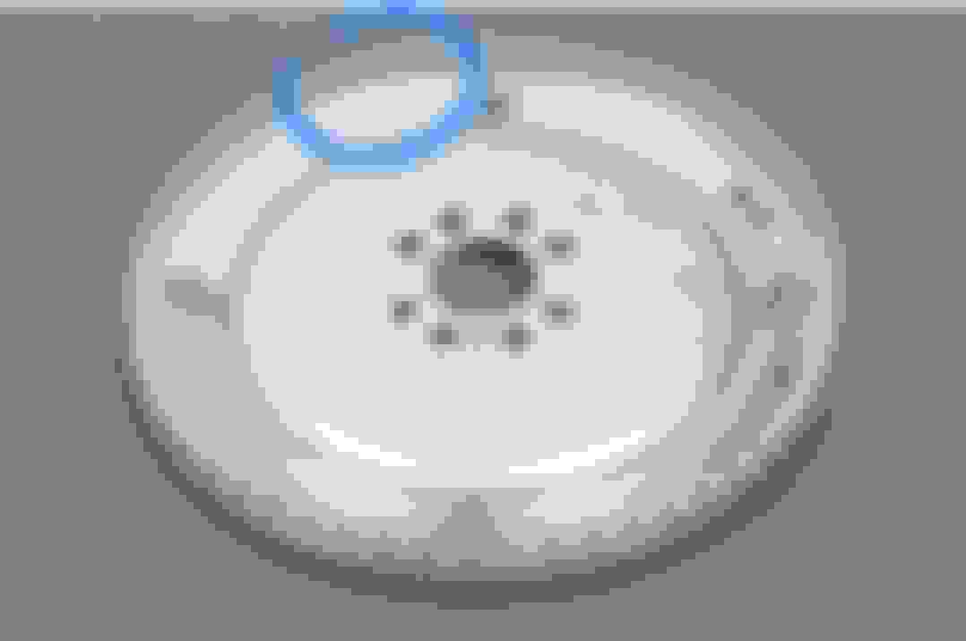
This is a picture from underneath the car of the crankshaft sensor, with connector attached, installed at the rear of the engine. The heat shield is partially bent open to get access. It was fiddly, but doable to get the sensor out. Bench testing the sensor confirmed the 0V signal on pin #2, so next step is to get a new sensor and install it. The sensor is an original MB part, the bit sticking inside the engine was surprisingly oily, not sure what to think of that yet. I wouldn't expect any oil present that high in bell housing.
Once I get a new sensor, I'll probably be able to get a descent crankshaft signal on the ECU. Then of course there's the question why this sensor failed within 400km. Did the oil interere with its working somehow? I'll have to leave this one upside down as well for a while, see if anything drips out.
Right, so this morning I got a new crankshaft sensor from the local MB dealer. It's a continental part, just like the one that I got out of the car. I decided to bench test this one before mounting it on the car. And no matter what I try, I cannot get this one to give a decent signal during bench testing.
5V to pin 3
GND to pin 1
Signal on pin 2.
Whatever I do, I keep getting 0V at pin 2, just like the old sensor. (0V difference referenced to either pin 1 or 3). This looks like a duff sensor. I'll order a cheap aftermarket one as reference, as this is starting to do my head in a little.
I'll be away for a few days so next update will take about a week.
Tap/touch, the end of sensor with ferrous metal or magnet, while reading voltage at signal wire.
Yeah, I've tried both magnets and iron cutlery to trigger something. This is the test setup.
But franklu, looking at your scope data in post #41 from a known good crank sensor, it looks to be a pull down sensor. So I would expect 5V with no metal close to the sensor, and a pull-down to 0 with something close. Though the WIS document describing how the ECU gets engine positions points at a pull-up type sensor:
Well, whichever type it is, the 2 sensors I have in front of me right now stay fixed at 0V. Which cannot be any good.
What are the chances you got a bad brand new MB brand sensor... Dang, this is not good.
Looking at the tone generator at the flywheel, and the waveform from WIS , it does fit the description of Pull Up of WIS since the 2 missing tooth at flywheel is a VOID and waveform by WIS shows zero/low volt. https://www.ebay.com/itm/165438271622
M276 3.0 has intercooler blocking the crankshaft pulley, so me can not spin engine by hand.
Yeah, I've tried both magnets and iron cutlery to trigger something.
But frankly, looking at your scope data in post #41 from a known good crank sensor, it looks to be a pull down sensor.
So I would expect 5V with no metal close to the sensor, and a pull-down to 0 with something close.
Though the WIS document describing how the ECU gets engine positions points at a pull-up type sensor:
Well, whichever type it is, the 2 sensors I have in front of me right now stay fixed at 0V. Which cannot be any good.
then it would make sense this being a magnetic pick up coil that works with motion opening and closing its magnetic field.
let's say 360 teeth per flywheel turning at 750Rpm divided by 60Secs equals 5kHz ticks near idle - it's hard to emulate that by hand.
The way the sensor runs off of 5V says it has a built-in electronic amplifier to help cleanup signal and drive the output line to ECU.
This sensor could be a distant cousin of serial LIN minus networking protocol - Trust Bosch for innovations!
Best here may be to trust the new MB sensor as a reference.
Last edited by CaliBenzDriver; Oct 16, 2023 at 06:24 PM.
Back home! I received the cheap aftermarket sensor and immediately put it on my multimeter, and again zero results, it's not responding to anything. Well, I'm not willing to believe they all happen to be broken, so here comes the scope for further probing on my bench.
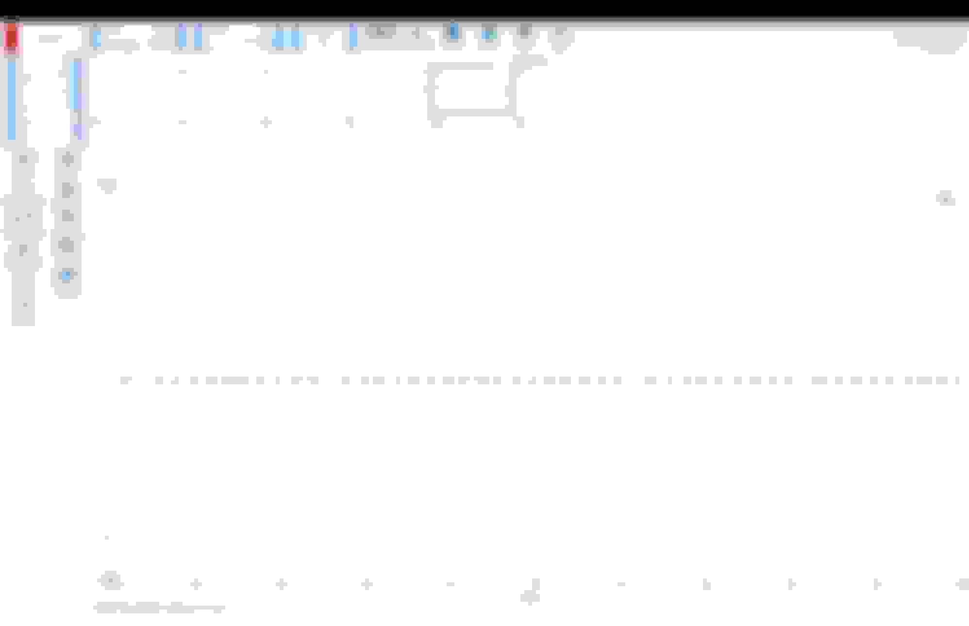
And, hanging head in shame here, with the scope I do get a signal. From all 3 CPS I have laying around by now. The thing is, these sensor give only give a short pulse on any changes in the magnetic field.
This pulse takes about 4ms from start till it gets below 1V again. I generated these pulses by inserting a metal allen key into my drill and spinning this in front of the sensor, hence the steady pattern. The pulse length is independent from the drill speed, even if I move the sensor manually towards a piece of metal, it generated only a single pulse once I get close enough to the metal.
The pulse is only measurable between pin 3 (+5V) and pin 2 (Signal), I see no pulses if I measure between pin 1 (GND) and pin 2. This last bit is very important, as I limited my measurements of the CPS on the car between Signal and GND. I have to measure this between +5 and Signal instead, which I just never tried. So it's time to put the sensor back in to the car and do my measurements on the car again, now knowing what to look for.
Learnings here, I have to know more specifically what the pattern of a known-good sensor should look like before I can conclude whether anything on my car has an issue. And I have to thread more careful in further troubleshooting, to avoid replacing random parts that are not faulty.
So we learned the crank sensor output is an open collector pulse . Taken out of circuit it's missing a bias to "+5V Sensor Ref. circuit". (Check that nothing colapses this +5V... shared line?)
Most conventional DVM are limited to 50/60Hz AC/DC and are totally out of their field with exotic signals ... that's where scopes shine in low voltage applications.
When you plug everything back together, what next step does this lead you to?
Everything back on the car. When I power the CPS from the Ecu, with the CPS signal pin #83 disconnected from the ECU, I can detect the pulses from the CPS (with the scope). That confirms that the sensor and sensor wiring works in the car, as far as I can see.
So next, everything connected to the ECU, ignition on / engine off, I can no longer detect the pulse from the CPS by back probing the ECU connector. The only thing I (once again) see on the CPS pin on the ECU (#83) is a copy of the intake camshaft hall sensor. This even goes so far, as connecting / disconnecting the left intake camshaft hall sensor just gives a similar 5V difference on pin #83.
Furthermore, I did the 53� test with the cam tone wheels to see if that all ligns up, and on the right intake, and left exhaust (these are easiest to access) everything lines up perfectly.
I checked the various common issues once more, with regard to the CPS sensor. There is no short between the 3 wires, the 5V gets to the sensor, ground is connected to ground etc. etc. Not much else I can think of except for the ECU itself right now.
CRANK pos sensor uses 5V and probably 1 amp max power supply.
CAM pos sensors uses 12V and outputs 5V signal. This is direct 12V power from Fuse 23 and 24 of front SAM 15 and 20 amps, depending on which bank.
So, if indeed ECM internally goes banana, it wont be a surprise that CAM pos sensor higher power supply could be the "attacker" of the 5V channel or CRANK pos sensor
Quick update, after talking to several companies regarding ECU tests and repairs, it all seemed a bit risky. When I explain the symptoms to them, they quickly become hesitant in their ability to fix such an issue. At the same time, I've found a replacement ECU, advertised as 'New', for a reasonable fee, comparable to most fixed-price repair offers. Hopefully this is really a virgin ECU, so that it can be a straight-forward install, where hopefully my baby Launch scanner is able to code it.
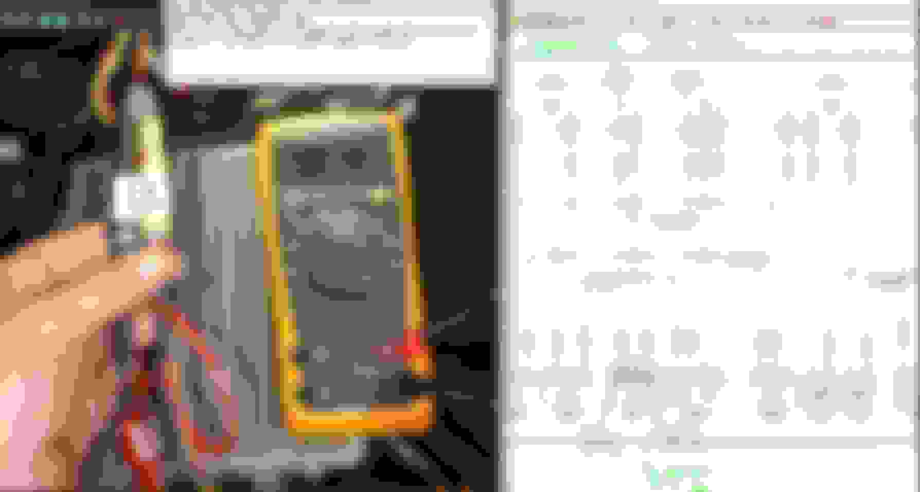
If you watch Pine Hollow Auto Diagnostics, look up "Beached Benz AMG" In Part 4, it shows how he programed a new ECU, He used a Launch X431 PAD V to do it Because the Thinktools Pros was not capable, I think the Autel MaxiSys Ultra or the Maxisys IM608 can too, If I'm not mistaken. But the lesser ones like mine just say, "This process is not available on this device"
I think he also references Super Mario Diagnostics, I think he gives a more in-depth play by play on the programming and how to connect to MB for the program files on a TopDon Phoenix Max.
Side note Topdon and Thinktool uses the Launch X431 program, the Autel is it's own program.
If you watch Pine Hollow Auto Diagnostics, look up "Beached Benz AMG" In Part 4, it shows how he programed a new ECU, He used a Launch X431 PAD V to do it ....
Side note Topdon and Thinktool uses the Launch X431 program, the Autel is it's own program.
Ooh, that was interesting to watch! The baby launch has exactly the same software (mine has versie 50.something, slightly newer). I'll have to check if the need options are available in this version though, not sure if the OBD connector which comes with the unit supports all necessary protocol. J2534 or something similar is needed I think for the programming.
But if I'm lucky, it's really an untouched, brand new, ECU that's underway, and my baby Launch has the options... I'll check on the car what's available!
Still waiting for the new ecu to arrive. Meanwhile I tried to find the options for control unit programming in the baby launch, and alas, it seems that option is not in there. So even though the little unit can do a lot, this is beyond its abilities. Once the new ecu has arrived, I have to find somebody to clone it for me.
Mercedes SLR McLaren 722 S Is Extremely Rare Example Modified by McLaren
Slideshow: A one-of-one U.S.-spec Mercedes-Benz SLR McLaren Roadster became even rarer after a factory-backed transformation at McLaren's headquarters.


 With that out of the way, I could see I got a steady 0V on #83, even while turning the engine by hand. That kind of confirmed the crankshaft sensor is broken.


 What are the chances you got a bad brand new MB brand sensor... Dang, this is not good.