When you click on links to various merchants on this site and make a purchase, this can result in this site earning a commission. Affiliate programs and affiliations include, but are not limited to, the eBay Partner Network.
The new ECU has arrived, it looks indeed to be a brand new unit, which is good news. Next step is cloning or programming the unit, I'm looking into my local options to see which route to take.
Meanwhile, I've managed to install WIS in a Windows 11 ARM VM on my Macbook M1 (phew) and I found this interesting snippet:
So it seems that the corrupt crank signal would automatically disable the high pressure pump. That would explain the exact behaviour I'm seeing, where there is pressure building during craning, but a sharp drop on ignition. Still good hope that the new ECU fixes it all!
Yesterday I got the ECU back after programming and coding. Unfortunately, after mounting the new ecu the issue is still there, where the rail pressure is ~4 bar after ignition of the car. I've yet to measure the crankshaft sensor on the new ecu, but it's probably similar to the situation before.
I had a chat with the actual guy that did the programming of the ECU yesterday when picking up the ECU at the shop. He suggested to start unplugging all sensors and actuators on the engine if the problem persists. Logic being that a short in a sensor/actuator can overload the power circuit in the ECU, leading to spurious readings on unrelated sensors. I think S-Priihadi already pointed towards this issue in post #96.
Next course of action: get the probe connected again to the ECU, first checking all 3 pins going to the crankshaft sensor referenced to ground. Maybe there is already a signal on the +5V driver or the GND wire referenced to the actual chassis ground. Once I can repeat the issue, I'll start disconnecting as many sensors/actuators as I can easily reach, and check if this has any impact on the crankshaft sensor signal.
When trying to think of the problem, I run into the issue that I don't have a solid background in electrical engineering. It's hard to understand the effect of say a bad chassis ground connection on one of the ground connector sleeves. Take for example Z6z2 into account, the common ground to the coils. If this has a bad connection, could this influence the ECU internal +5V driver? Or if a short occurs in one of the sensors/actuators driven by the ECU, would this influence the +5V driver? I realise I'm not enough up-to-speed to deduce the expected behaviour in these fault scenario's, hindering troubleshooting. Anyway, it's a learning curve and I am enjoying it (most of the time).
This is sad news, the new ECM not giving the solution expected.
Don't worry, me too do not have education background in electrical engineering.
We all can learn some.
Bad grounds can have weird effect, not because of only low voltage but sometimes zero voltage becomes higher-positive simply because it is not
a complete circuit and hence no return path to ground it to become zero volt.
Defective sensor/s can take down other sensor/s is very possible, however do note which sensors are direct Front SAM supplied 12V , which sensors are
from ECM 5V supplies.
How frustrating, it's like the issue is staring me right in the face but I cannot recognise what it is that I'm seeing.
For a few minutes tonight, I was able to read the crank signal on pin 83 on the ECU. Test conditions were: car was switched off for about 20 hours, I only pressed the start button once to wake up the car. Intake manifold was disconnected, including various sensors (intake temperature, air flow etc) as well as actuators (throttle valve). I turned the engine slowly by hand and could see the ~5V Crank sensor signal regularly dipping to 0V for very short pulses. However, after fannying about a bit with ignition and wiring, and not keeping track of what I as doing, I got the old behaviour, a copy of the cam signal on pin 83. Hmmm..
Then I disconnected the left exhaust cam sensor (this seems to be the signal that's being copied), and the 5V signal on pin 83 showed some noise. No wait, carefully wiggling the connector on the cam sensor give me the ability to rise the voltage on pin 83 to 10V. What??? So a specific set of connected / disconnected pins on the camshaft hall sensor influences the voltage on pin 83?? Would this be a disconnected ground on the hall sensor, leading to a current drain over the signal pin of the hall sensor into the ECU?
I decided to measure, with the scope, the voltages on the hall sensor connector (disconnected from the actual sensor). It's fed by 12V (from the front SAM?), there's a 0V on a pin, and the signal pin carries 5V. That's probably the bias voltage from the ECU, to check if the sensor is connected? That would at least imply that the hall sensors, even though fed 12V from the SAM, also get 5V from the internal 5V circuit inside the ECU.
Anyway, it's there, right in front of me, and I cannot recognise what it is that I'm seeing. Meanwhile I'll continue checking sensors and grounds.
S-Prihadi, you mentioned before that the hall sensors (as well as others) are fed directly from fuses in the front SAM. On the WIS document describing the ECU engine connector, I can see that these sensors get their positive voltage from Z7/35z2 and Z7/38z1. This points at 'Circuit 87 M1e connector sleeve'. Does this Circuit 87 point at a specific fuse in the SAM? This would help to check those wires as well.
Now its a good time to map out all you sensors/components power source.
Which one are from Front SAM and a 12V .
Which one are from ECM via its 5V driver/s.
You will then create something like my table below, but my table below has not included the 5V sensors supplied by the ECM, you must make that 5V sensors/device list.
After this, you need to make a list of the ground wiring for all 12V sensors and 5V sensors , where are they from ?
This way you can see better where "cross-contamination" can occur between 12V and 5V sensors.
One thing for sure, your crank pos sensor gets its ground from ECM and not cylinder head.
Z7/43 is the ground for the 3 above 5V sensors.
To why ECM does not use engine metal/cylinder head as ground for these 3 sensors, is probably because this 5V sensors are "filtered" sensors, they get cleaner signal
hence it is on purpose designed to have ground from ECM and not engine metal.
===================
All camshaft position sensors Bank 1 and Bank 2, all 4 of them. Let's trace its ground connection.
So, this Z7/44 ground splice is actually connected to ECM and not engine metal, the W-s type of ground. Pin 70 of M connector, labeled as NWG_M2
Power source of these 4 camshaft pos sensors are those splices Z7/35z2 and Z7/38z1
Some higher amperage device will get ground from W-s type of ground , engine metal or chassis metal.
Understand all the wiring first, and then you can troubleshoot better and faster.
Have fun cataloging your wiring.
Last edited by S-Prihadi; 11-10-2023 at 04:52 PM.
Reason: ADD INFO
In light to Jeddie ECM issues.
I have upgraded my own documentation for the ECM to show all sensors ground source/s, just in case Uncle Murphy play naughty on me
Here is what I made and Jeedie should do something like this, for easier troubleshooting.
Find attached, PDF. I revised it again. A more complete one.
Last edited by S-Prihadi; 11-11-2023 at 12:45 AM.
Reason: ADD INFO
I think you are leaning back towards poor GND, right? One of the circuit (12v? or 5v?) is floating with missing reference... we can try to test that assumption quickly.
🤞
Remember the special screw post on firewall near cowl. It is ECU dedicated, right?
We can not Ohm out live circuits but we can scope them! Look at its voltage for floating and being non-zero reference.
Go ahead and bypass questionable GND with a spare strap at ECU connector (no need to deal with cowl PITA for testing).
Once you know you have a good GND strap for test, you can see if your sensor signals are still getting mixed up.
Last edited by CaliBenzDriver; 11-11-2023 at 01:01 AM.
Reason: shortcuts for testing
It would be wise for Jeedie to start from new clean slate.
01A. Clean up the un-listed W-TF ground under the car to starter motor bolt and the one at suspension strut , from battery negative, called W10.
For the unlisted W-TF ground wire : https://mbworld.org/forums/e-class-w...ital-wire.html
01B. Other high power grounds of the ECM are : W16/5 and W11. Test using load test of 10 amps,
01C. Equivalent grounds of M276 3.5NA to my 3.0 , see 2 tables below. Test using load test of 10 amps,
.
02. Test using load test of 10 amps, all power wires which are from Fuse 22, 23, 24, 25 and 27.
Lots of great info! Thanks again guys, this is really of great help. I've been searching in WIS for over an hour to understand those Z connections and relation to fuses, and I totally overlooked the vehicle connector diagram showing exactly what's going on 😄. And that undocumented ground will get proper attention as it seems to be really close to the crankshaft sensor, which suffered from heavy corrosion due to a coolant leak. That coolant may have found its way to that ground connector as well.
For sensor grounds where they are from ECM Con-M, pin 70 and 19, 2 amps is more than enough. Sorry, I copy-n-paste 10 amps LOL
However, since there are splices, you need to load test to each and every sensors.
The ECM small pins are MLK 1.2, these are their male terminal dimensions, so that you do not over-expand the female one at ECM wired connector.
This is , just in case you have not bought the MLK 1.2 and SLK 2.8 male terminals which are the bigger ones at ECM wired connector.
I did a lot of careful measurements over the last 2 hours. From what I can gather, there is an intermittent short between #83 and #59 on the ecu engine connector, bridging the signal wires from the camshaft sensor and the crank sensor. It's not always there, hence the earlier conclusion that the short is within the ECU, as I couldn't detect it with the ECU disconnected. But in the current state, the short is there without the ECU connected.
This might also explain the behaviour I noted in post #129, where a specific position of the camshaft hall sensor connector leads to 10V on the crankshaft sensor signal wire (#83). The specific position is probably where only 12V and signal are connected to the sensor, and the GND pin is not connected. This could lead to the hall sensor acting as a simple resistor between the 12V and signal wire, instead of acting as a voltage divider. The resulting 10V is then passed on to the signal wire of the crankshaft sensor due to the short. Anyway.
I peeled back the first 15cm of the wiring loom to check for any damage there. As the wire to the camshaft sensor is on the first branch from the main loom, it's only a limited bit of the loom where a short can occur. As far as I can tell, the wiring is in perfect condition within the loom itself.
So I'm getting the idea that the short is within the connector itself. To confirm (or exclude) this, I have to de-pin either of pin #83 or #59.
See this (bad) photo of the pins in the connector.
Has anyone ever tried to de-pin the ECU connector itself? There seems to be this big red ring around the pins, that can be pulled towards the front of the car. From other connectors I worked with (Bosch 2 pin?) I recall this to be an extra seal as well as an extra lock for the pins. Would it make sense to remove this red ring and then try to de-pin #83?
The ECU connector getting an internal short would be pretty extreme - So I am going to guess there is likely a wrong assumption along the way misleading to next step, right?
===============
---> Pls describe the test that leads you to conclude the cam and crank wires are shorted (inside ECU con.)
===============
- This we know is the MAIN ISSUE: BOTH SIGNALS ARE INTERMINGLED (no question on that!)
- We are trying to figure how they appear to be intermingled.
- Make sure you're not ohming a live circuit. Bring power down first.
It's a good great thing you are able to reproduce root causing short-circuit... let's locate it!
🤞
Last edited by CaliBenzDriver; 11-13-2023 at 08:16 PM.
This is the setup I have right now. I back probed the camshaft hall sensor on the signal wire:
As well as back probing the ECU connector on the crankshaft signal wire (the pink one):
The ECU is not connected, the camshaft hall sensor is not connected, however the crankshaft sensor is still connected.
In this setup, I'm reading 0.4Ohm between the 2 leads.
If it's easy to de-pin the ECU, I'd like to remove either #83 or #59 and see if the short is gone. Do keep in mind that #83 and #59 are next to each other, #59 is in the second row, right behind #83. However, if I'm going to mess up the connector by unpinning it, I have to look into other options. Things I can think of right now that might cause this issue, besides a short in the connector:
- I'm not back probing the ECU correctly, and the needle is going in sideways, connecting to another pin.
- There's a shield in the connector somehow, and I'm hitting that shield instead of the wire.
- There is a short between the two wires in the bit still covered by tape.
You have this well defined! 👏
There is a straight 0.4Ohm short between crank and one cam signal without ECU connected in circuit.
This is a near perfect short value...
> Mixed up positions:
-- Are you sure the people who rewire things before you did not mixup some of these pinouts ??
-- DOUBLE CHECK the right leads position at ECU connector endup at the right position at crank and cam connectors.
-- Don't trust or follow the colors, instead beep between ECU con. to cam + crank cons 6 distinct positions.
You want to be sure the pin at ECU beeps with the pin at sensor. Then you can trust that solid. I'm afraid the 0.4. Ohm short is between pins that are misplaced....
> Initial 0.4 Ohm test:
-- What happens to 0.4 Ohm short when you unplug crank sensor... still appears shorted?
> Move cam probe:
-- Right now one of the probe is down the line near cam sensor - Move this probe near the ECU con. ie. near where the crank probe is located. See if changing cam probe location makes a difference.
Eng GND as reference > no-no
> Do not reference engine GND for sensors!!
-- These noise-free inputs have their own floating GND not directly related to engine/chassis GND screw.
-- To measure cam + crank supply voltage or output beware of what special Reference point is in use by ECU.
-- when scoping live: do not short Sensor GND with engine GND through scope GND connections.
Hopefully something helpful comes up from these steps
Last edited by CaliBenzDriver; 11-14-2023 at 02:06 PM.
Well, whatever it is I did, the short is no longer there. I went probing things in various way, I may have moved something inside of the connector, or, worst case, I've been probing diagonally all the time, ending up at the wrong pin. If that last bit is true, I hang my had in deep, deep shame. Good news is, that there is a crank signal now readable at the ECU connector.
So back on with the manifold and all disconnected sensors/actuators, and I tried a startup. I get a solid crank pulse:
Bad news: low fuel pressure is still there, including the rough idling etc. It idles for maybe 2 seconds before the engine dies.
To really pinpoint a fueling issue I decided to squirt some brake cleaner into the air inlet and then start the engine. This improves things massively, I get a solid idle for at least 10 seconds. That confirms the fuelling issue, so we're roughly back at post #81. As the engine runs a bit longer, I can get some useful data om my scan tool. The fuel pressure on the rail drops to ~1.8 bar and error P008700 is raised (low fuel pressure). And of course there is a strong unburnt fuel smell.
There are really only two options that I can think of right now. I already probed all camshaft hall sensors (they give correct data) and now the crank signal is there as well. So the ECU knows the engine timing/position, further proofed by a reasonable idle running on brake cleaner fumes. Further, I measured a sound low pressure fuel system, and there is of course the unburnt fuel smell, hinting at an over fueling situation.
So either the HPFP is controlled with bad timing on the PWM signal, which could be caused by cam timing being off. Of course, there is a solid ramp-up of pressure during cranking, so this only occurs after startup. Which could relate to the VVT unit on the cam driving the HPFP lobes?
Or there is a massive fuel leak through one or more injectors as soon as ignition starts (but not during cranking, and there is no pressure loss on the system if the engine is off). Would this make sense?
01. Assuming camshaft tone ring does not shift out of its laser alignment marking
You can first scope the intake cam pos sensor on both banks.
If both are the same or only 2 degrees apart, we know the Bank 1 intake camshaft where the HPFP fuel pump is at, is in time.
What we try to do is to see peak pressure variation being off-time, in the case of a camshaft tone wheel being shifted.
Here your 2 channel scope is a handicap as you need to see crank pos sensor, ignition trigger and that pulse pressure sensor , total 3, as minimum data input, surely better a 4th channel to see intake camshaft tone wheel to see how many degrees is the shift
Or you can buy the 3 injector seal kit, special tools related to seal change and injector pull out, proper sealant yada yada.......... to open up the cylinder head cover of Bank 1 and inspect
visually the intake camshaft
or raise the white flag and use the service of Diagnose Dan who is also in the Netherland. https://maps.app.*******/FgNUwWRQyC4GVgav6 <<< crap, this forum block google map link
I'll see if I can give him a call today for a tele-consult..
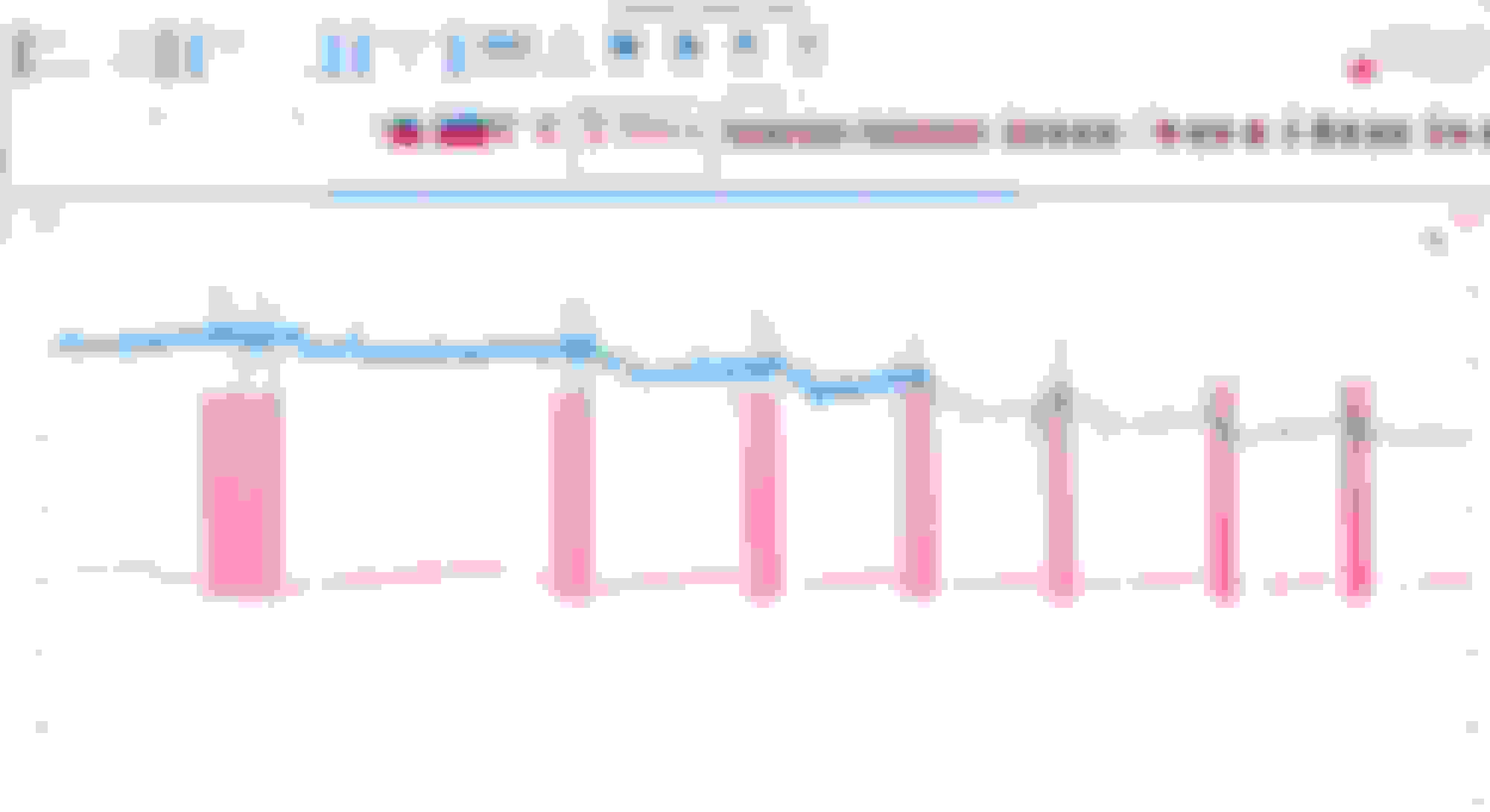
Meanwhile, I captured the PWM signal of the HPFP solenoid versus the rail pressure voltage. It's a bit noisy as the 2 signals don't share a common ground. I was actually expecting the rail pressure to increase during the PWM signal, however there hardly seems to be any influence at all.
Blue line: pressure sensor voltage, red line: PWM signals to qauntity valve.
Also, the pressure ramp-up seems to be unrelated to the PWM timing (!):
Blue line: pressure sensor voltage, red line: PWM signals to qauntity valve.
Your pico is not the automotive one with floating ground to -30Volt, so sometime u can not use more than 1 channel at a time if the sensors do not share the same ground for reason of noise control or what not
In fact caution must be practiced when using shared ground scope
I agree, it's difficult to get good readings with the cheap scope I have on combined data. You can seen the ground drift on the red line between the pulses. The PWM and pressure sensor are themselves not grounded outside of the ECU, however the '-' of the PWM signal does not equal ECU ground I think.
Some interpretation and care is needed to make sense of this data. However, the increase of pressure, independent of the operation of the solenoid, is clear from this data.
I tried giving Diagnose Dan a call today, however he's not in the workshop today. I've dropped him a message, see if he can be of help, I realise I'm really clutching at straws right now. I also really need to better understand the workings of the quantity valve. According to the 'Introduction into Service Manual' from Mercedes, the M276 and M278 the quantity valve should default to open: 'Quantity control valve is reenergised and therefore open', both at limp-home mode and shutoff. This does not match the increase in pressure after shutoff, where pressure can remain at 25bar.
Just found the drawing of the HPFP shows a check valve after the pump piston into the rail. So even if the quantity valve is open, pressure is still held in the rail.
Did not get a really helpful response from DiagnoseDan, just a referral to their subscription based technical support platform aimed at workshops. Not really aimed at the enthousiast I feel.
Right, current plan of attack after pondering on this for a few days, and getting lost in various Youtube diagnostics binge sessions..
Things ruled out:
- It seems the buildup of fuel pressure after shutoff of the engine is expected behaviour for a GDI engine with a check valve in the HPFP. It indicates that there are no stuck-open injectors.
- Timing of the right intake cam, as inspected through the sensor opening, is spot on. So no suggestion of a jumped phaser or reluctor.
- HPFP is new, and I can hear the solenoid ticking away if I put a screwdriver on top of it. So solenoid is working it seems.
- Low pressure flow and pressure still seems to be okay and not the cause of the issue.
Unexplained behaviour for now:
- Why does the HPFP not seem to build any pressure during running, as witnessed with the scope?
- Why does the rail pressure increase during cranking, independent of the control of the solenoid?
Thinks to check:
- Once more, with all hall sensor now working, get a scope reading of cam/crank timings.
- Disconnect the HPFP solenoid and run the engine in that state. Validate if the initial pressure rise is still there, if so the pressure rise is not an indication of a working HPFP.
- Check the solenoid sound not ticking with the solenoid disconnected, to confirm that the ticking I can hear indicates a working solenoid.
If the above all checks out (solenoid sound gone, pressure still being build up during cranking, cam/crank timing in good order), I will probably conclude that the HPFP is not pumping. So then I would have to check the cam follower and the position of the 3-lobe cam driving the pump, to see if that has moved on the cam.
Did not get a really helpful response from DiagnoseDan, just a referral to their subscription based technical support platform aimed at workshops. Not really aimed at the enthousiast I feel.
Right, current plan of attack after pondering on this for a few days, and getting lost in various Youtube diagnostics binge sessions..
Things ruled out:
- It seems the buildup of fuel pressure after shutoff of the engine is expected behaviour for a GDI engine with a check valve in the HPFP. It indicates that there are no stuck-open injectors. In a normal running engine, heat rise after engine kill can make the 188 BAR fuel pressure at the rail to exceed 200 BAR from heat soaking.
- Timing of the right intake cam, as inspected through the sensor opening, is spot on. So no suggestion of a jumped phaser or reluctor.
- HPFP is new, and I can hear the solenoid ticking away if I put a screwdriver on top of it. So solenoid is working it seems.
- Low pressure flow and pressure still seems to be okay and not the cause of the issue.
Unexplained behaviour for now:
- Why does the HPFP not seem to build any pressure during running, as witnessed with the scope?
- Why does the rail pressure increase during cranking, independent of the control of the solenoid? If you meant the pressure increase is only up to 7BAR, that is the low pressure fuel pump pressure which can enter the HPFP because it is a normally open
quantity valve.
Thinks to check:
- Once more, with all hall sensor now working, get a scope reading of cam/crank timings.
- Disconnect the HPFP solenoid and run the engine in that state. Validate if the initial pressure rise is still there, if so the pressure rise is not an indication of a working HPFP.
- Check the solenoid sound not ticking with the solenoid disconnected, to confirm that the ticking I can hear indicates a working solenoid.
If the above all checks out (solenoid sound gone, pressure still being build up during cranking, cam/crank timing in good order), I will probably conclude that the HPFP is not pumping. So then I would have to check the cam follower and the position of the 3-lobe cam driving the pump, to see if that has moved on the cam.
That's the work planned for the weekend!
( I do not want to scroll up 100+ pages )
BTW, did you see the cam follower condition when you install the HPFP ?
I believe during cranking, on a normal healthy engine, the HPFP is operated by ECM, to prepare for good fuel pressure....more so when engine kill has been a day ago or more, where
fuel pressure may have fallen below 120BAR. Idle fuel pressure at the rail is usually 120BAR.
I actually replaced the cam follower when I renewed the HPFP. I checked the cam lobe visually through the little hole when the pump is removed, though I did not spend to much time on it. If all of the above checks out, I'll remove the pump and the pump housing so I can get better access to inspect the lobes.
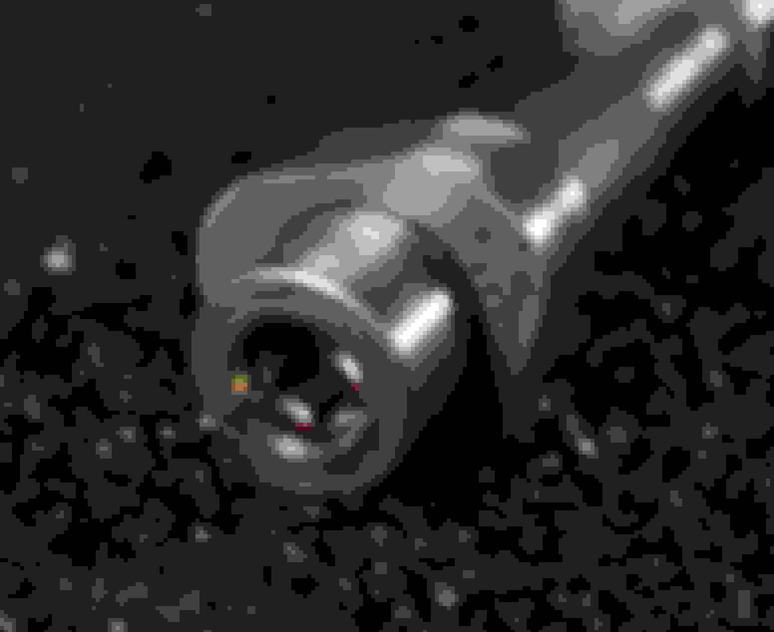
Small change, but does anyone happen to have a picture referencing the pump cam lobes to the actual camshaft position? This would be useful in checking whether the position of the lobes has shifted. As in the below picture, it seems the lobes are pressed onto the shaft, it's not a milled item:
I have asked the same question for my 4 lobes HPFP camshaft, where are the 4 peaks in degrees ?, in respect to a healthy non-shifted camshaft tone wheel or lobes.
I would find that out only next year as soonest, when and if I replace all the plastic timing chain guides, as per my 10th year refurbishment program.
The prospect that our camshafts are *not single piece machined billet ( *seems so as you explained ) but rather pressed fit lobes, it scares me too.
Even with a scope, what I do not know yet is :
01. Is the HPFP Y94 valve always starts and end its activation within the 60 degrees window valley to hill peak in a 3 fuel lobe camshaft with 120 degrees x 3 lobes ?
There are two ways to control pressure/volume by Y94, in my mind.
AA. Pulse power only a fraction of the 60 degrees window , but always within valley to hill, the compression.
Where within the 60 degrees, let say a 45 degrees Y94 signal ACTUALLY start and stop ?
or
BB. Pulse power all of the 60 degrees window valley to peak ( compression ) for maximum pressure and then reduce pressure a bit by pulsing a bit more while peak to valley occurs which is the decompression mode.
If we can inspect visually and measured those 3 or 4 fuel lobes position in degrees, only then we can confirm properly the operating window of 60 degrees (your engine ) and
my engine 45 degrees.
.
02. The other factor I am still uncertain is the VVT sprocket acceleration of angle change.
VVT being dynamic is an added calculation algo the ECM need to calculate for Y94 activation/pulsing.
I am sure predictive algo is involved here and not wait for angle result from Cam-Pos-Sensor and then pulse the Y94, it will be too late as Y94 will have lag, and so will VVT sprocket.
From Y94 point of view, cam-pos-sensor must be its reference.Regardless of VVT angle of change, Y94 peaks at the fuel lobe stay the same X degree difference to the camshaft zero degree.
From VVT point of view, the CRANK-Pos-Sensor must be the reference , as ECM would use it as primary angle reference for sure. ECM zero degree is based on CRANK-Pos-Sensor
==============
Actually you can measure your 3 hill peak of the fuel lobes as is now, but you wont know if that is the correct one or not.
First you must get a proper template for the vibration damper/main pulley to see how many degrees you are spinning it by hand from the known zero or cylinder 1 TDC.
Use this to print : https://www.blocklayer.com/timing-tape
You must compensate for a non-activated VVT retard/advance, aka locked position.
You then see visually inspect the peaks of the 3 fuel lobes visible from the HPFP mounting hole. I think if the main pulley printed template is good, you can be 5 degrees accurate.
I once used a pencil or sort to define the lobe peak, just like one using a screwdriver rising on a piston to see TDC
.
========add========
Come to think about it, let say you managed to log the positions of the 3 peak lobes.
At the least you can later see if the Y94 activation does fall on the 60 degrees vallet to hill peak (compression ) or not, regardless there is a possibility
your camshaft say has shifted its zero degree. If the timing of Y94 is wrong, you can see it.
Last edited by S-Prihadi; 11-18-2023 at 05:50 AM.
Reason: add info
Oh, good idea to get a reference, and it�s pretty straightforward actually.
I can run the engine with the vvt solenoid disconnected, forcing the cam in a known good position.
Through the cam hall sensor window, I can visually reference the cam position.
I can easily read the line positions using a dial gauge, especially if I leave the cam follower on the lobe.
that, combined with the degree scale on the pulley, will give readings accurate to at least 1 degree.
From my previous measurements of Y94, I conclude that the pressure control is dictated by the total duration of the pwm signal to Y94.
The duty cycle of the pwm signal seems to be fixed, the signal seems to be predetermined to be enough to keep the solenoid in the closed position.
In my screenshots, you can find examples where the total time of the pwm signal equals the total time without a signal. In other places, the total time of the pwm signal is shorter than the total time without a signal.
This would equate to a maximum valve closing of 60 degree (valley to top of lobe) if you see what I mean.
 11-02-2023, 06:51 AM