When you click on links to various merchants on this site and make a purchase, this can result in this site earning a commission. Affiliate programs and affiliations include, but are not limited to, the eBay Partner Network.
First time posting here in x164 forum. I am active in the w164 forum. This post is for my missus’ GL320 2007. Before anyone mentions searching similar threads in the forum, I have already done that. This issue I have might be unique. I am trying to make my reverse camera and rear parktronic work. My scanner showed no fault codes for PTS (Parktronic System)
Section ONE: Rear parktronic
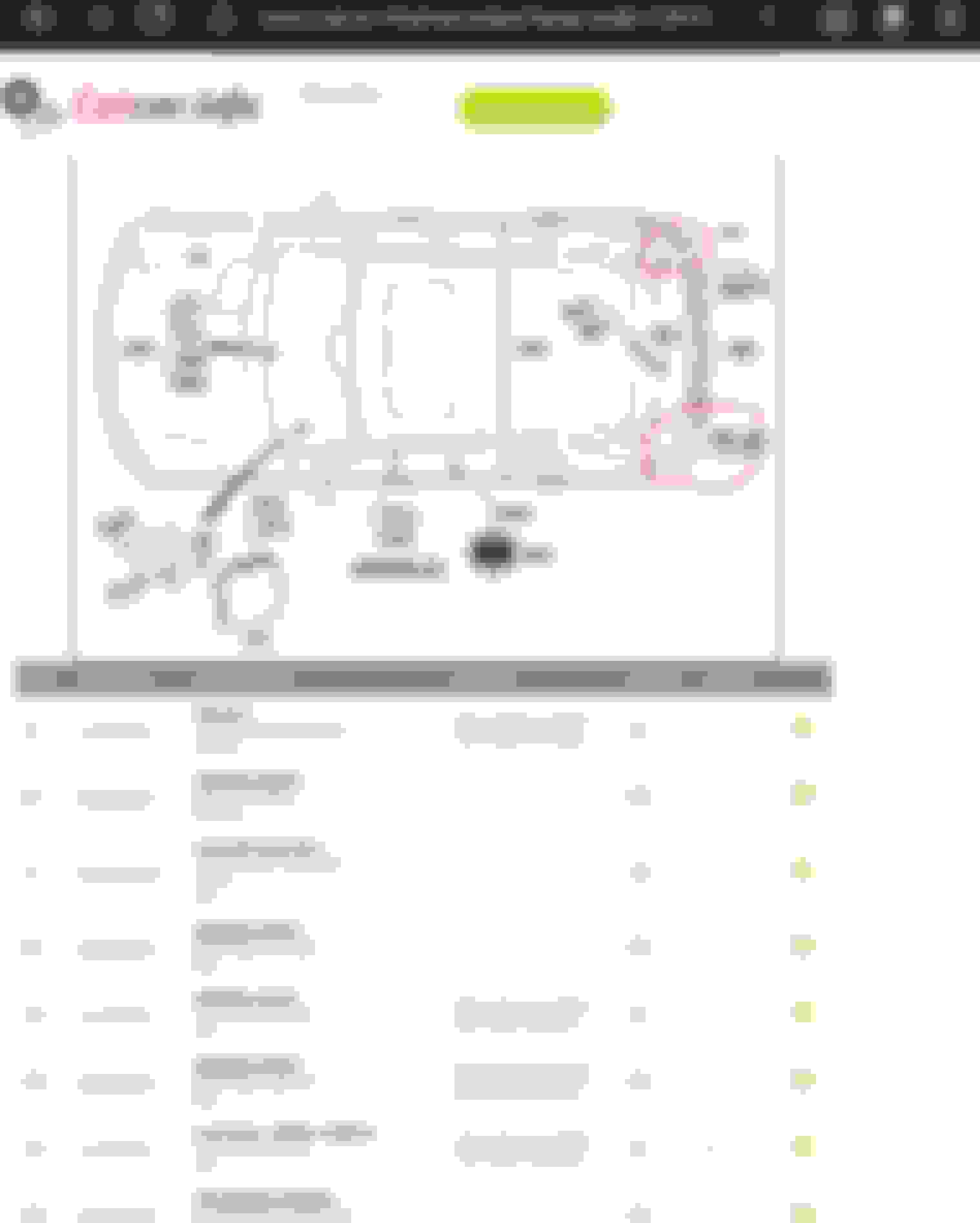
Rear sensors inoperable, might think nothing special here. It is a 16 year old vehicle and parktronic has plenty of drama with it. Here is what I found with my scanner. Pictures below. Pic1 and Pic2 taken with the gear in park. By depressing the brakes, the readings change. This tells me voltage is being fed into the wires. Pic3 and pic4 are the voltage readings. Same conditions, gear at park and brake depressed.Pic5 are the possible points of shorting with brake lights.
Pic1: Footbrake off, sensor readings Pic2: Footbrake ON, sensor readings Pic3: Footbrake off, voltage reading Pic4: Footbrake ON, voltage reading Pic5: Possible points of contact with brake lights
Section TWO: Rear camera
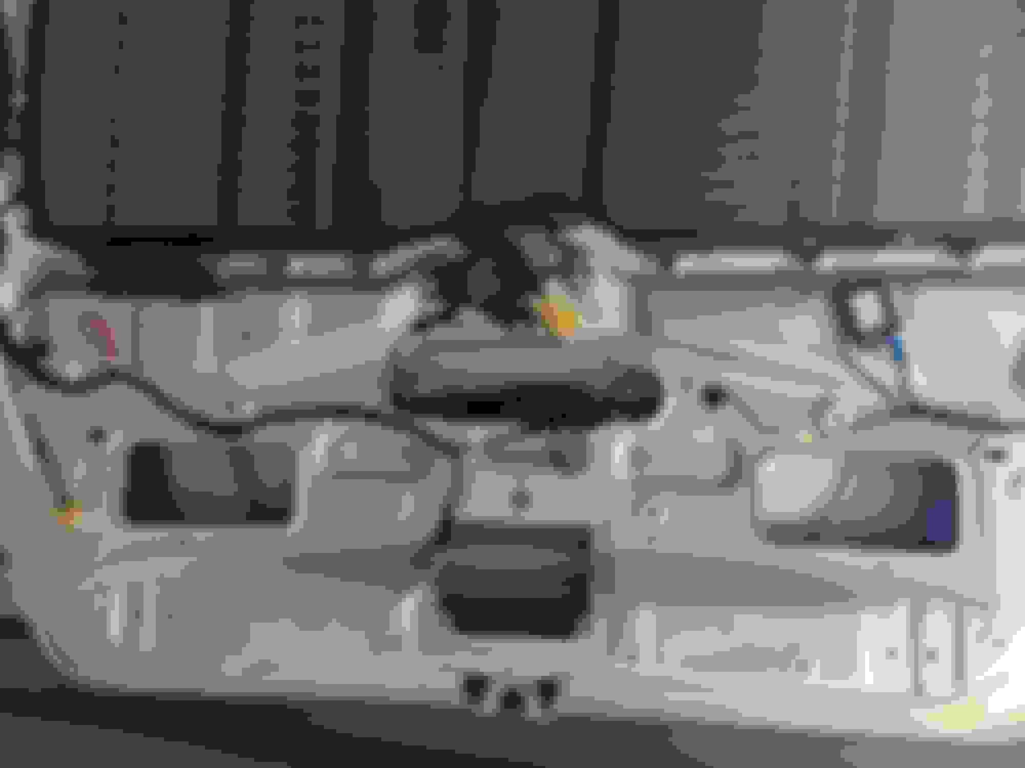
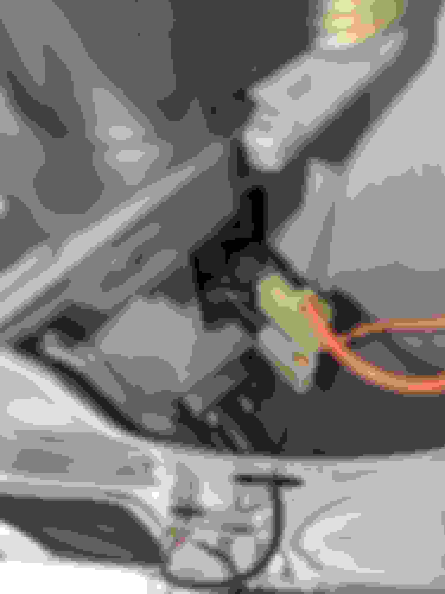
The rear view camera works intermittently. I noticed it will stop working after a rain downpour. Decided to open up the tail gate trim and seal the camera gasket which was split. Good so far and will ibserve until next rainy days. Pic6, pic7, and pic8 shows an accumulation if a brown-like substance over the years. Pic9 showing the tail gate setup with trim removed. Pic10 showing the water ingress.
Pic6: unknown wax-like substance Pic7: unknown wax-like substance Pic8: unknown wax-like substance Pic9: rear tail gate innards Pic10: camera with water ingress
Questions:
Most possible point of shorting with brake light circuit? Pic5
If the short is at parktronic display, will it be possible for the voltage to reach all the way to the sensor. To mess wih the sensor readings. Pic2
Ok, I have issues with my parktronic and it's on my list to look at. I tend to get a false close alarm that seems to be moisture related. My is front of car.
However, parktronic won't work while in park gear. Can you repeat the test while in reverse or neutral? Rears will also be deactivated if the car thinks a trailer is plugged in.
Unlikely to be a short as it is affecting all sensors. The power and ground is common to all sensors, but the signal wire is not. You need power for the sensor to work, and it returns a signal based on the result of the distance (maybe ultrasonic). For all distances to be the same, it can't be shorting signal wire, so you assume that the voltage to the sensor is being changed. It would probably need the 12V to run (knowing car voltage varies a bit so can't be sensitive between 10 and 15V).
Parktronic control box is not located in the boot, so unlikely to be related to rear water ingress (that is usually the rear SAM).
Good to see you hear in the x164 forums.
Putting gear in reverse will display red lights and a long beep. Thatin itself is a diagnostic code which some thread here explained. It is a malfunction of sorts.
i said it was a short somewhere since pressing the footbrake would instantly change the distance readings from the scanner. That meant that the ?brakelight? circuit was influencing the sensor readings.
the Parktronic lights nor the tonal beep changes differ even though I place objects directly behind the car.
Sorry, didn't even realise it was you. I'll try and head out your way some time. Can't promise to be helpful, but at least we can check whether same thing happens on a working system.
Doubt it is a short, as your supply voltage to the sensor remains the same. I would have thought this would have been an issue if common power/ground had issues. Otherwise you are shorting all sensor wires. This seems a bit more unlikely, unless it's at a connector.
help me out for a sec?
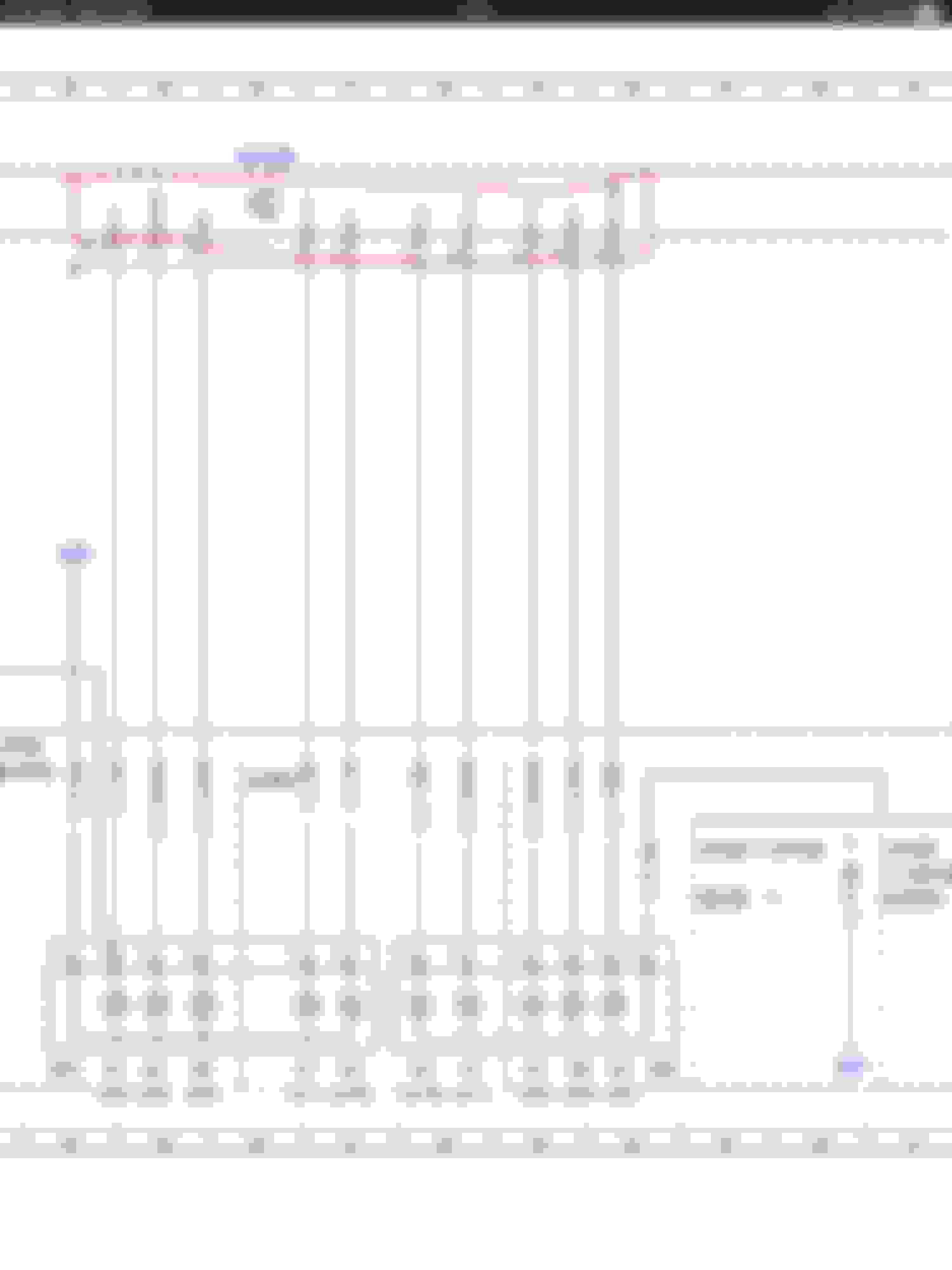
i have started viewing the file and looking at E3e3 for left reverse lamp connections. I am still trying to sort out my visio viewer. However, screenshots will suffice for now. I am looking for screenshots at rear SAM all the way to E4 receptacle connector.
EDIT: i found this thread and this seems helpful. Will let you know.
I am going to hijack my own thread. Anyone know what these numbers are inside the red annotation?
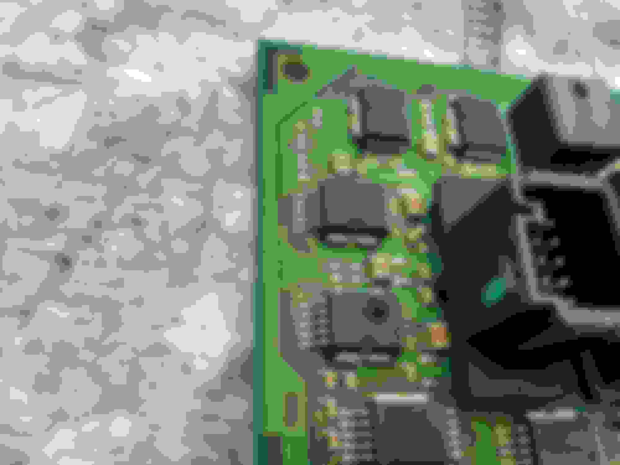
I know the bottom ones are for the pin numbers on Connector D (rear SAM). I am asking for the ones inside the rear SAM (N10/8). Are they perhaps the semiconductors on the PCB?
I am going to hijack my own thread. Anyone know what these numbers are inside the red annotation?
I know the bottom ones are for the pin numbers on Connector D (rear SAM). I am asking for the ones inside the rear SAM (N10/8). Are they perhaps the semiconductors on the PCB?
I am confused about why you are looking at the rear SAM. The wiring diagram for my 07 indicates Parktronic mostly involves the Parktronic module, with the front SAM connected. Is that why you said "hijack"?
Are you going down this path because you see voltages changing when you press the brake pedal?
In any event, those annotations are probably some reference to SAM internals. If you feel like sitting there with an ohmmeter, you could probably trace from the connector pin to the chips on the board. Not sure what you'd do with that info, though. Just make sure to do this with the SAM out of the vehicle!
Yep, I have hijacked my own thread. Rear SAM has nothing to do with PTS. But alive19 is a good friend of mine and the previous posts were directed more for him.
Anyhow, I have identified the two points in my previous pictures. I just need another weekend to open them up and see where the brakelight voltage is shorting with the PTS wires. I have a good idea it will be in the PTS display at the rear gate since I have seen pinch points on the harness (where the gate closes). I simply need a free day to do proper tests. FYI, the rear gate will have the PTS display circuit and gate brakelight circuit in close proximity.
I am curious to see what you come up with. A pinch point would not surprise me. The electricals are fragile and underbuilt. I tore the ribbon cable in my driver door; other people have fried a fuse box trace that is fused to 30A.
I am confused about why you are looking at the rear SAM. The wiring diagram for my 07 indicates Parktronic mostly involves the Parktronic module, with the front SAM connected. Is that why you said "hijack"?
Are you going down this path because you see voltages changing when you press the brake pedal?
In any event, those annotations are probably some reference to SAM internals. If you feel like sitting there with an ohmmeter, you could probably trace from the connector pin to the chips on the board. Not sure what you'd do with that info, though. Just make sure to do this with the SAM out of the vehicle!
Now that you mention the PTS wiring diagram. Can you uplod it here please?? I am still trying to sort out a dwf viewer for @alive19 suggestion in the previous post. I found the files but cannot open it. Hopefully you can share whatever information as well for the PTS block diagram.
It's a free download and can open dwf and other CAD files. Doesn't integrate into browsers and is unnecessarily bloated.
If you have a short on the brake wire and sensors, you should be able to measure some resistance between the two. I still think it's unlikely, but then again my clunking driveshaft of doom was solved by a software update. EDIT - just noticed the -ve goes back to the control box, so maybe it has it's own relative ground, so possible a short will pull a voltage. Unfortunately the control box is under the passenger seat floor, so it is likely to be easiest to pull the rear bumper off to access the connector to measure resistance to the brake like circuit.
I don't think any of the PTS wires run through the rear hatch/gate. The sensors run through the bumper from the left side and the display runs up inside the car (from the right through the pillar).
you might be right. I had a wuick look yesterday and the PTS didn’t look like coming from the gate wiring loom. Anyhow, a free day and I will look into this.
It's a free download and can open dwf and other CAD files. Doesn't integrate into browsers and is unnecessarily bloated.
If you have a short on the brake wire and sensors, you should be able to measure some resistance between the two. I still think it's unlikely, but then again my clunking driveshaft of doom was solved by a software update. EDIT - just noticed the -ve goes back to the control box, so maybe it has it's own relative ground, so possible a short will pull a voltage. Unfortunately the control box is under the passenger seat floor, so it is likely to be easiest to pull the rear bumper off to access the connector to measure resistance to the brake like circuit.
I don't think any of the PTS wires run through the rear hatch/gate. The sensors run through the bumper from the left side and the display runs up inside the car (from the right through the pillar).
Did you ever post exactly what was the solution to the clunkity clunk?
FWIW I have noticed that MB likes to construct circuits in which the ground, not the supply, is completed.
Note my clunky was very specific to feathering the throttle while driving. Just at that point where the drive line would unload and effectively be almost coasting.
So I had this error today, frustrating as heck until I went around the back and realize that I’m still carrying my bike rack around. This defeats the system and it rolls around in error mode for the rest of the drive.
So in your case you were getting spurious inputs from the sensors, thinking that something is back there during the initialization phase.
Do you have your photo back to front on the sensor voltage (ie pic3 and pic4)?
I've had a look at mine and I have 8.4V when it is operating and infinite distance (greater than 255cm).
Is it dropping to zero volts when the brake is pressed (noting that if you put the handbrake on, it disables the parktronic).
No objects on the rear during these tests. So readings should be greater than 255cm always.
Pic3: park brake on, gear on park and footbrake not pressed. This is when i get zero volts.
Pic4: park brake on, gear on park and foot brake depressed. This is when i get 8.4V. The reading is correct and same as yours but the sensors shouldn't be active since gear is in park and park brake on. This is where I have a idea that the brakelight circuit is activating the sensors and giving false reading.
So I’m going to save you the time.I’ve just tried to replicate your test with car in R and park brake on. When I play with the brake pedal, sensor voltage drops of towards 0. Decayed to .2 with a second or so.
Weird behaviour, but yeah your brake isn’t shorting with the sensor.
Probably doesn’t really help you much in solving the problem.
Edit - ok slightly different to you but same same. Try in reverse with no parkbrake - yeah without crashing.
Some help is better than no help.
I was about to say your readings are the opposite to what I have. My sensor voltages goes 8.4V when i press the footbrake. I will do some tinkering on the long weekend.
Last edited by DLB_Adelaide; 06-08-2023 at 07:14 AM.
I might have an update for this. Never got the chance to look into the wiring technically. But the PTS is now intermittent operation. When it works, rear PTS goes from one yellow light then full lights wih no transition periods. I have posted having problem with the camera as well. I noticed when my camera display is faulty, this is when the PTS works (barely). I noticed my COMMAND head unit has a role to play with my camera and ?PTS?
I saw a thread in w164 forum where a member placed a relay to ensure proper voltage.
DLB_Adelaide - did you ever resolve your Parktronic issue? I am having what seems to be exactly the same issue on my 2008 ML320. No obvious shorts where I've seen the rear sensor wiring so far (I deleted the sensor connector in the boot fairly early on to rule out corroded pins).

 05-21-2023 | 06:42 AM