When you click on links to various merchants on this site and make a purchase, this can result in this site earning a commission. Affiliate programs and affiliations include, but are not limited to, the eBay Partner Network.
During an oil change today I planned on checking my solenoids. Three were dry, the driver side, cam shaft solenoid, not the magnet one, looked clean, but when I stuck a qtip in there, there was a bit of oil. The engine has about 60k miles on it. I am going to replace the two front ones with the new version that is supposed to be better made.
Also had the coolant over flow hose snap at the intake. Need that too.
Ah dude, that's what happened to me last Summer. My Wife said there was a coolant leak and I found that three (3) legged coolant line from the reservoir to the radiator to the intake broken. I then proceeded to break (accidentally) the other four (4) plastic turbo lines & fittings while replacing that one! Get ready to replace them all, lots of talk on these forums about turbo coolant lines breaking. Believe them, they are real. I did the work myself and it cost me over $500 for the lines and the fittings, but that beats the **** out of $3000 the dealer wanted and $1900 that an Independent Shop wanted.
We love the car, but keeping up with the maintenance on it is somewhat disappointing, never would have believed there were this many things on the car that needed maintaining other the normal maintenance. Luckily I can turn wrenches so I can stay on top of it for a minimal price, but I'm still a little disappointed in it. My Mother had an '83 MB 280E that she sold when it had 340,000 miles on it and after I wrecked it. Car was fast, reliable and maintenance free.
I thought the '13 GL450 would be as good or better but sadly, I'm not sure.
Yeah, these are pretty much garbage. The problem is there is nothing comparable. The X7 is a bit smaller. the GMs are garbage.
Anyway, i have to believe the leak in the CPS is the path from inside the sensor to the pins. I am thinking about taking one of my leaking ones and silicon as much as possible of the plug side and see if that matters. On the other hand they are only $38 and its not worth messing with. More of a matter of curiosity because there are no obvious cracks, it must be internal of the outer column of the sensor, if that makes sense. Unfortunate that a sensor is a maintenance item.
Is the temporary repair pulling the connectors apart and cleaning them? Good idea. That's what I would do.
That is the only option you have until new sensors and magnets are installed.
If you replace the cam position sensors, and are willing to spend some time to find the source of the leak, many people on the site would be grateful. So far no one has posted the true root cause as to why the sensors leak, only that they do in fact leak. My hypothesis is that the black plastic injection molded sensor body is compromised by a crack or thermal/chemical attack, letting oil into the electronic portion and into the connector. It remains an hypothesis until a detailed study is done on a sensor known to have leaked.
A rubber hose clamped on the sensor connector socket with some air pressure applied to the hose, combined with soapy water is a test I would like to see done on a failed sensor. Bubbles would indicate air passing through the sensor body.
Mr. Chassis, I went back to the start of this thread and read in a post about replacing cam cover seals. I have a couple of questions about this resolution and others;
1) How many cam covers are they?
a. If just two (2) are they in the front of the motor?
2) Are there more than four (4) camshaft sensors?
Would it be wise to change the Cam Cover Seals to help combat this oiling issue? Assuming there is only the two (2) in the front of the engine, that shouldn't be a big deal, is that a paper gasket or a rubber seal?
Thank you sir!
Chad
Chad, cam cover seals are not related to oil in the harness. Cam magnets and cam position sensors are related to oil in the harness. There are 4 position sensors and 4 magnets for a total of 8 devices that could potentially leak into the harness.
There are two cam covers, they are sealed with liquid sealant to my knowledge. I haven�t had mine resealed because they aren�t leaking.
There are two cylinder head covers, not the same as cam covers. The cylinder head covers are at the front and are the plate to which the cam magnets are attached. Leaking cylinder head covers are a common factory defect on the M276 engine. I had mine resealed under warranty by the dealer after three requests. So far no leaking.
Awesome, just wanted to make sure I was on the right page.
It seems to me that if the oil is being forced or pressured into the Sensors and into the harness, could this be the result of excessive crank case pressure? Do these cars have a PCV valve or an Oil Catch Can? Or some other way to relive pressure that could be pushing oil thru the sensors? Perhaps a Crank Case breather?
Chad
I believe there is a breather at the back of the engine if i recall
Awesome, just wanted to make sure I was on the right page.
It seems to me that if the oil is being forced or pressured into the Sensors and into the harness, could this be the result of excessive crank case pressure? Do these cars have a PCV valve or an Oil Catch Can? Or some other way to relive pressure that could be pushing oil thru the sensors? Perhaps a Crank Case breather?
Chad
You are onto something!
Crankcase pressure is forcing oil out of these engines from every weak joints. Some people report popping their dipsticks by driving.
Besides air-oil "centrifugal pan" allows massive amount of oil in the M276 intake that MB added a collection cup near the throttle body to prevent oil leaking back out of the engine intake. The never washed valves on this direct injection engine love the fuzzy oil coating.
Awesome, just wanted to make sure I was on the right page.
It seems to me that if the oil is being forced or pressured into the Sensors and into the harness, could this be the result of excessive crank case pressure? Do these cars have a PCV valve or an Oil Catch Can? Or some other way to relive pressure that could be pushing oil thru the sensors? Perhaps a Crank Case breather?
Chad
My view is the plastic injection molded sensor and magnet housings are cracking, allowing oil into the sensor internals, from where it migrates to the connector pins and into the harness via capillary action. Not crankcase pressure related.
It is a relatively easy test to confirm the leaktight-ness of a failed sensor, but so far no one has done the test. Take a rubber hose of sufficient size that it fits around the sensor connector. Secure the hose to the sensor with a hose clamp, thereby sealing it. Secure the other end of the hose to an air pressure supply, sir example a bicycle pump or air compressor. Spray soapy water on the sensor and apply air pressure, and look for bubbles. Also the sensor could be immersed in water and the air pressure applied, again looking for bubbles.
Until some tests are done the true root cause remains unconfirmed.
Thread made me take a look at mine on a GL450. Having no issues, but all 4 cam sensors had oil inside connector. Just replace and be thankful I found them before there was an issue? It doesn't look like there is oil on the wires out of the sensor.
I'm also replacing O2 sensors. Are the front sensors called a lambda probe? I can't find an aftermarket for them, was going to use Bosch for the rear.
Thread made me take a look at mine on a GL450. Having no issues, but all 4 cam sensors had oil inside connector. Just replace and be thankful I found them before there was an issue? It doesn't look like there is oil on the wires out of the sensor.
The oil isn't visible on the outside of the wire, it's inside the insulation and wicks along the metal wire. You need to pull the ECM from the top of the engine and unplug those connectors and check for oil on the pins. I had oil there. What I also did was prop up the ECM vertically for a couple days with the connector side down, and paper towels stuffed in between the connector pins. Gravity and the wicking action of the paper towel will get some of the oil out. Then plug everything back together, drive it for a few days, then unplug and clean again. After a few cycles of this, I didn't notice any more oil on the connectors. Everyone's experience will be different because the amount of oil and how far along the wires it migrated will be different from engine to engine. Good luck!
My view is the plastic injection molded sensor and magnet housings are cracking, allowing oil into the sensor internals, from where it migrates to the connector pins and into the harness via capillary action. Not crankcase pressure related.
It is a relatively easy test to confirm the leaktight-ness of a failed sensor, but so far no one has done the test. Take a rubber hose of sufficient size that it fits around the sensor connector. Secure the hose to the sensor with a hose clamp, thereby sealing it. Secure the other end of the hose to an air pressure supply, sir example a bicycle pump or air compressor. Spray soapy water on the sensor and apply air pressure, and look for bubbles. Also the sensor could be immersed in water and the air pressure applied, again looking for bubbles.
Until some tests are done the true root cause remains unconfirmed.
I figure I’d post here since this thread is pretty active. This maybe a wider spread issue than imagined. (at least for me). I have a few cars I maintain for “friends and family”. Out of my small sampling of a dozen cars with M278 from 2013-2017, so far I’ve found oil leaking from the cam sensors into the plug/harness on 7 of them! The lower position, drivers side, camshaft reference sensor always seems to be the worst (and first) offender. None of the cars threw codes in XENTRY either….
The latest is a ‘13 SL550 with 44,683 miles. I’ve found cam reference sensors leaking on 2013-2016’s with as little as 30,000 miles. The camshaft magnetic adjusters in the front appear to leak much less than the camshaft position/reference sensor on top of engine. Coupled with the sacrificial harness, The camshaft magnetic sensors don’t appear to be as big of an issue. I’m also wondering if some of these engine failures may have this issue as a contributing factor. I’m surprised there is no sacrificial harness for the reference/position sensor but Mercedes probably figured those are easy to replace.
I still have the ones I recently took off in the pics below. ( btw The plug was soaked, I should have take a picture of them) I’ll give them a “leak down” test tomorrow to see what happens…..
It is not a gravity pull for oil, more like crankcase pressure - your ECU connector is in a higher position than most of sensors.
The bigger question why they leak. I tend to think it is because of gasoline runoff from injectors diluted into engine oil and then evaporated through vent system.
The vent system is positive pressure itself.
This is very interesting. The CPS that was leaking, much less so than the above was the drivers side front. If there is a crack, it has to be internal, in that column inside of the outer cylinder. I spent a good amount of time trying to find a leak, no luck, other than confidence that it is not in the outer cylinder of the CPS.
All this being said, probably easier to just replace them for $40. I still need to do the ones in the back, will do the air filters at the same time. I am curious if there is a place to add a catch can in the system. Would this type of engine benefit from that?
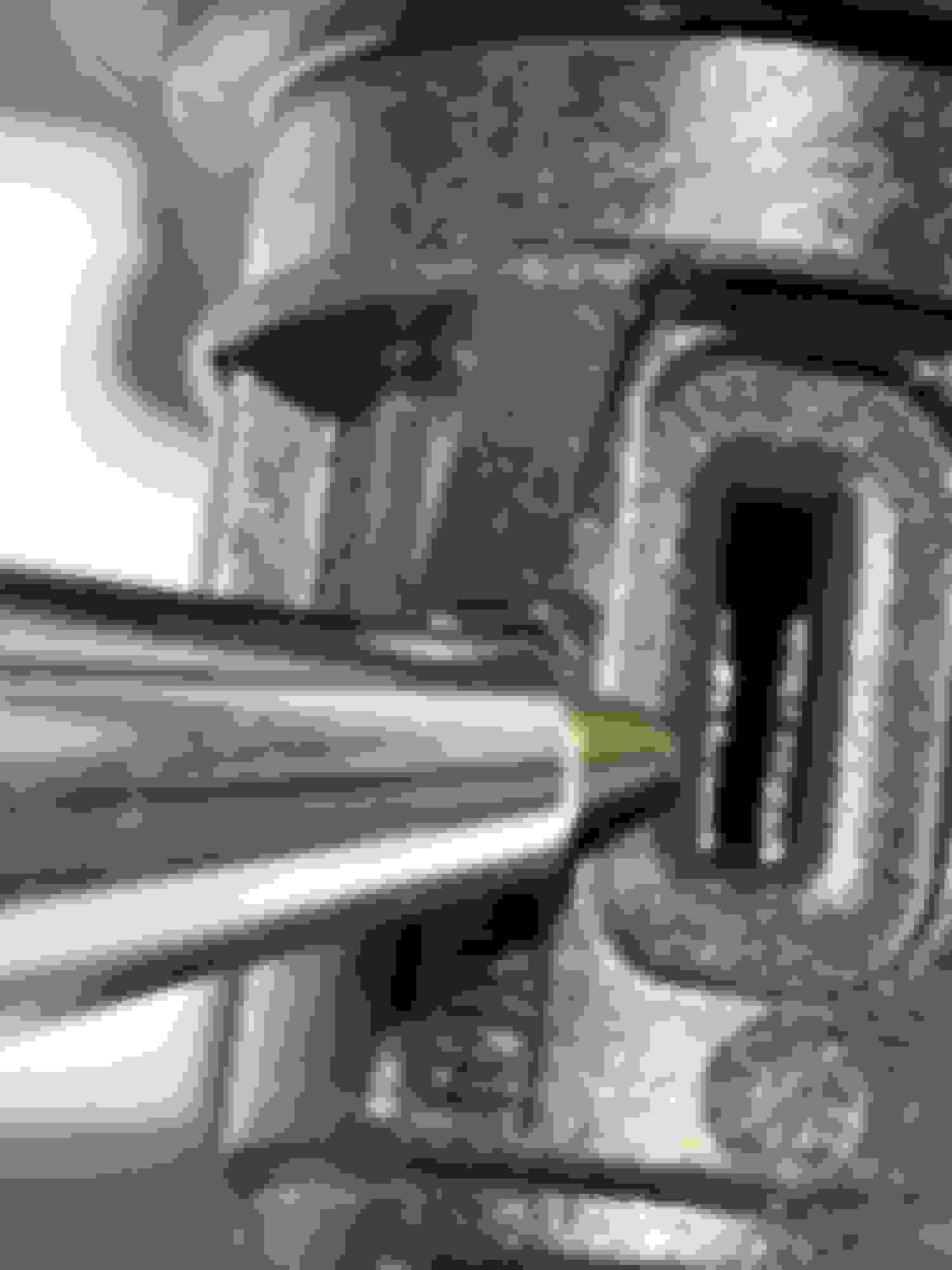
I'm not sure it's a crack, but rather expansion and contraction over so many cycles hardens the plastic. At some point the pin connectors (and maybe the internal structure of the sensor) at the top of the cam position sensor separate from the sealed surface and creates a gap where the oil can escape. The pins/wiring have to connect to the magnet somewhere. I noticed there is a slot in the cam PS and think thats where the oil ingress probably happens. (see pic). My guess is theres an inner part and an outer part to those cam sensors. which may also separate with age hardening. After all, these did not leak when new but rather this condition started over time/heat cycles.
Think of the wire sheath as a small straw. The thinner the straw the easier the fluid moves thru it. Also the temperature differentiation between the engine and outside temperature may help this action.
Pressure has to enter the equation at some point in order for it to get past the sealed pins on the Cam PS to reach the ECU. I'm not sure it's capitulary action BY ITSELF. But it may also play a part. Gravity must also plays a role, as it appears to start with the lower Cam PS. I think in theory, there shouldn't be much positive crankcase pressure but in actual operation, there will be positive pressure in there.
Basically it's an error propagation of sorts, that add up to create this condition.
I'm going to try to cut one apart on my mill when I get some time (hopefully this week) to inspect construction to see just where/how the oil is getting to the pins.
Unfortunately I don't have a new one to cut apart to compare but it should at least reveal how the oil is getting thru the sensor into the wiring. It may be just the new ones use a different material that is less prone to hardening, But my guess is they changed the internal design too.
Last edited by crconsulting; Mar 24, 2022 at 11:05 AM.
I'm not sure it's a crack, but rather expansion and contraction over so many cycles hardens the plastic. At some point the pin connectors (and maybe the internal structure of the sensor) at the top of the cam position sensor separate from the sealed surface and creates a gap where the oil can escape. The pins/wiring have to connect to the magnet somewhere. I noticed there is a slot in the cam PS and think thats where the oil ingress probably happens. (see pic). My guess is theres an inner part and an outer part to those cam sensors. which may also separate with age hardening. After all, these did not leak when new but rather this condition started over time/heat cycles.
Think of the wire sheath as a small straw. The thinner the straw the easier the fluid moves thru it. Also the temperature differentiation between the engine and outside temperature may help this action.
Pressure has to enter the equation at some point in order for it to get past the sealed pins on the Cam PS to reach the ECU. I'm not sure it's capitulary action BY ITSELF. But it may also play a part. Gravity must also plays a role, as it appears to start with the lower Cam PS. I think in theory, there shouldn't be much positive crankcase pressure but in actual operation, there will be positive pressure in there.
Basically it's an error propagation of sorts, that add up to create this condition.
I'm going to try to cut one apart on my mill when I get some time (hopefully this week) to inspect construction to see just where/how the oil is getting to the pins.
Unfortunately I don't have a new one to cut apart to compare but it should at least reveal how the oil is getting thru the sensor into the wiring. It may be just the new ones use a different material that is less prone to hardening, But my guess is they changed the internal design too.
Good ideas. It would be great to see a cut open sensor.
My view is the plastic injection molded sensor and magnet housings are cracking, allowing oil into the sensor internals, from where it migrates to the connector pins and into the harness via capillary action. Not crankcase pressure related.
It is a relatively easy test to confirm the leaktight-ness of a failed sensor, but so far no one has done the test. Take a rubber hose of sufficient size that it fits around the sensor connector. Secure the hose to the sensor with a hose clamp, thereby sealing it. Secure the other end of the hose to an air pressure supply, sir example a bicycle pump or air compressor. Spray soapy water on the sensor and apply air pressure, and look for bubbles. Also the sensor could be immersed in water and the air pressure applied, again looking for bubbles.
Until some tests are done the true root cause remains unconfirmed.
Well I can see no leakage/air bubbles at room temperature using my jerry rigged leak down test. (at least on MY cam position sensors).
I can guarantee two of them were soaked with oil (as pictured above).
I tested all 4 twice. I clamped the hose at the very top of where the sensor seats in the engine (see pics below). There should have been plenty of pressure applied to the body of the sensor. I used a clear hose with my air nozzle clamped to one end and the sensor clamped to the other end. Applied air pressure from my compressor as high as a sustained 75psi. I saw absolutely no bubbles in mine, submerged under water. btw these are marked part number A2769050143
Higher temperatures must be a catalyst.
Originally Posted by chassis
Good ideas. It would be great to see a cut open sensor.
I'll try to cut one up.
But after that leak down test, I think it may only help to see both older and newer revised part side by side.
As I mentioned above I can't help but wonder if this isn't the catalyst for some of the engine failures. While some may indeed be cylinder coating related, some of the broken piston/ring land issues may be a result of ECU getting inaccurate data leading to ignition timing issues. And who knows, running rich can wash oil of the cylinder walls and plug Catalytic Converters. One things for sure it's not going to help anything...
Last edited by crconsulting; Mar 24, 2022 at 02:49 PM.
Well I can see no leakage/air bubbles at room temperature using my jerry rigged leak down test. (at least on MY cam position sensors).
I can guarantee two of them were soaked with oil (as pictured above).
I tested all 4 twice. I clamped the hose at the very top of where the sensor seats in the engine (see pics below). There should have been plenty of pressure applied to the body of the sensor. I used a clear hose with my air nozzle clamped to one end and the sensor clamped to the other end. Applied air pressure from my compressor as high as a sustained 75psi. I saw absolutely no bubbles in mine, submerged under water. btw these are marked part number A2769050143
Higher temperatures must be a catalyst.
I'll try to cut one up.
But after that leak down test, I think it may only help to see both older and newer revised part side by side.
As I mentioned above I can't help but wonder if this isn't the catalyst for some of the engine failures. While some may indeed be cylinder coating related, some of the broken piston/ring land issues may be a result of ECU getting inaccurate data leading to ignition timing issues. And who knows, running rich can wash oil of the cylinder walls and plug Catalytic Converters. One things for sure it's not going to help anything...
Excellent and well done. Interesting there were no bubbles.
If the oil is inside the engine and it escapes outside of the engine into the harness and inside the wire insulation, what leak path exists besides through the internals of the sensor?
I agree heat is a contributor. Probably also vibration. Not easy to reproduce with a DIY test bench.
If you are willing to explore a bit further, how about conducting the same test but with the sensor immersed in near boiling water? Boil the water with the sensor immersed (hose attached), remove from the heat source and apply air pressure.
A cut open sensor will also be interesting. An axial cross section from sensor tip to connector pins would be a suggestion.
Excellent and well done. Interesting there were no bubbles.
If the oil is inside the engine and it escapes outside of the engine into the harness and inside the wire insulation, what leak path exists besides through the internals of the sensor?
I agree heat is a contributor. Probably also vibration. Not easy to reproduce with a DIY test bench.
If you are willing to explore a bit further, how about conducting the same test but with the sensor immersed in near boiling water? Boil the water with the sensor immersed (hose attached), remove from the heat source and apply air pressure.
I was thinking of pre-heating the sensors in the oven. Along with submerging in hot water. I’ll have to wait ‘till the wife goes shopping and away from home for a while Lol 😆
Originally Posted by chassis
A cut open sensor will also be interesting. An axial cross section from sensor tip to connector pins would be a suggestion.
That was my plan (Axial cut). That material may be brittle
We’ll see…
Last edited by crconsulting; Mar 26, 2022 at 05:47 PM.
A bandsaw might give a clean cut. You mentioned a mill, I would think the sensor internals might be snagged by the mill flutes. Your call at the end of the day, and thanks for digging into this.
Welp, So today while the wife was out I had access to the oven
Heated the Cam Sensors to 300 degrees for 40 minutes. Boiled hot water, submerged the part and and applied air pressure.
Resulted in.....
No air bubbles/leakage. Unbelievable! Maybe it has to be more constant pressure, but I couldn't get them to leak no matter what I tried. Any of them!
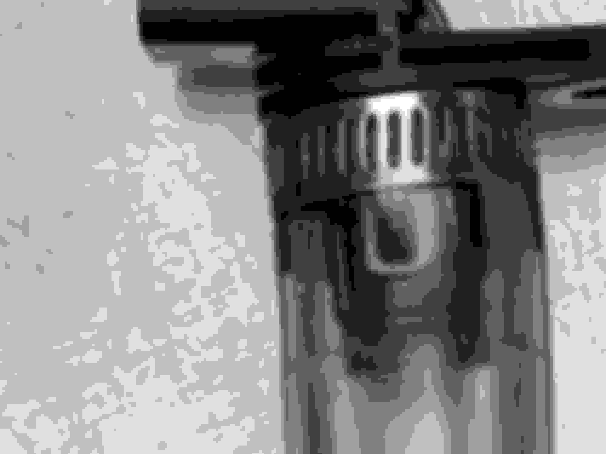
So I proceeded to mill them down to various depths. Lo and behold, I found one of them has a cavity between the inner wiring cross section and the outer housing. Not sure actual manufacturing technique used, but whatever the case, there is definitely and air gap in there. See picture 4.
It would appear to be some sort of injection molding process, but it didn't completely fill. Whether this is where the oil ingress is developing is inconclusive, but suspect. It would appear to be some sort of capillary action with the oil seeping into that air cavity and maybe a porosity materials issue of that inner molded area. That inner polymer material appears to be somewhat porous and slightly softer than the outer shell. I'll see if I can find another cavity in the other sensors. It may be a luck of the draw as to where they appear. So far it's the only one I found milling from the front. I'm somewhat limited by the way I have to hold the part in the vice.
My conclusion, for what it’s worth, is that the inner polymer must be porous, allowing the oil to travel thru the connectors, into the wiring.
It would be interesting to compare the new part number with these.
Varying depth cuts
Last edited by crconsulting; Mar 28, 2022 at 11:23 PM.
Thanks for taking the time and effort for this. Very interesting. If you are up for one more step, it would be interesting to see a cut 90 degrees to the cut you made. In other words, an cut down the middle of the connector throat showing where the pins leave the sensor and mate with the harness.
Reminding ourselves that oil leaves the engine and enters the harness by way of the sensor. Need to determine the leak path. Clearly the connector is involved. And clearly the portion of the sensor immersed in/exposed to oil is involved. This means the part of the sensor after the mating surface to the engine cover is where to look for the leak source.
it would be interesting to see a cut 90 degrees to the cut you made. In other words, an cut down the middle of the connector throat showing where the pins leave the sensor and mate with the harness.
I was still in the process of cutting one down further when I posted.
Here's the result. I believe the inner material to be porous. Look at the air cavity between the two bottom connector too. It has a different density compared to the outer shell. It feels "softer". It cuts different too. You can see it has a different surface finish after the end mill cut.
Mercedes SLR McLaren 722 S Is Extremely Rare Example Modified by McLaren
Slideshow: A one-of-one U.S.-spec Mercedes-Benz SLR McLaren Roadster became even rarer after a factory-backed transformation at McLaren's headquarters.