When you click on links to various merchants on this site and make a purchase, this can result in this site earning a commission. Affiliate programs and affiliations include, but are not limited to, the eBay Partner Network.
I just did my dashcam on the GLE and ended up not running any wires to the back of the car. I just used the Rain/Headlight sensor behind the rear view mirror as it is always on. I used a small hardwire kit (https://www.ebay.com/itm/28269199807...8AAOSw70xZ3x~d) that perfectly fitted inside the housing where the Augmented Reality/dashcam should have been (I do not have that option, blame the chip shortage!). I just tapped on the back side of the harness using RC board male jumper pins (https://www.ebay.com/itm/40343536954...oAAOSwe8ph8QXr) so that if I want to remove it I'll just pull em out and no harm done. There is a lot of space behind that cover and I am sure if you have the Augmented Reality cam you will still have space to hide the hardcam wiring kit and cables. Just make sure it is taped properly so that it won't get loose and rattle behind the cover. I used the existing wiring clips to secure some of the wires to tidy it up a bit as well. I have the voltage cut-off at 12v just to make sure it won't drain the car battery. The dashcam should be recording 24/7 right now unless voltage drops to 12v then it shuts-off. So I'll see how long it will run before I get a message from the Mercedes Me. The dashcam I am using is using a capacitor type so I won't have to worry about swelling batteries.
Usually Dashcams require ACC (i.e. hot when car is running), BAT+ (constantly hot to enable parking mode) and GND.
@shotgun_banjo Can you pls elaborate regarding the Rain/Headlight sensor? Is it constantly hot (i.e. BAT+) or only when the car is running (i.e. ACC)?
I suspect it is the latter as I do not see any point to have constant +12V going to that sensor? Am I wrong?
[QUOTE=gls-fan;8901732]Usually Dashcams require ACC (i.e. hot when car is running), BAT+ (constantly hot to enable parking mode) and GND.
@shotgun_banjo Can you pls elaborate regarding the Rain/Headlight sensor? Is it constantly hot (i.e. BAT+) or only when the car is running (i.e. ACC)?
I suspect it is the latter as I do not see any point to have constant +12V going to that sensor? Am I wrong?[/QUOTE
It is always hot. Other aftermarket dashcams also taps to the rain sensor as well.
It is always hot. Other aftermarket dashcams also taps to the rain sensor as well.
Got it thanks.
Is there any ACC signal then? Always hot wont work as the dashcam will stay powered on all the time when there is no ACC to signal when engine is off.
I finally manage to get the cable routed so that it is hidden.
Thanks to tinman831 for helping me in removing the trims
The clips that holds the trim piece are those below, and with the black rubber washer:
There are a total of 7 clips holding the entire piece in place, 2 of each side, and 3 in center. Once you know the location of those clip, its very easy to pull out.
And final product
@zengshengliu did you end up routing your wire a different way to get that install? I ended up running the cable from the front dashcam to the passenger bottom side, back seat bottm side then up to the trim and had that hideous extra cable hanging down when the door's closed (just like how you did it the first way). This fixed second way that you have, did you keep the same route or you went a different route to get that really shortened effect from removing the back trim?
@zengshengliu did you end up routing your wire a different way to get that install? I ended up running the cable from the front dashcam to the passenger bottom side, back seat bottm side then up to the trim and had that hideous extra cable hanging down when the door's closed (just like how you did it the first way). This fixed second way that you have, did you keep the same route or you went a different route to get that really shortened effect from removing the back trim?
You are talking about wires hanging at the top of the trunk window when the hatch is closed right? On the car side, I just remove the weatherstripping of the hatch and push the cable in (from fuse panel cover side up), I opened the trim piece (shown on one of the image, on car side, not hatch side), open the rubber connecting "tube" and push my wire through.
As for the trim piece on the hatch (the one between the hatch side "tube" and the back glass), I did not remove it. I just open up the rubber "tube", use some wires I have laying around (I think I actually use one of the metal band from an old windshield wiper) to fish the wire through that panel. I am sure there is a way to remove that trim piece also, but what I did works for me.
This is what I have currently which is what I think you had originally. Now I just need to make it neater and fix it� how long did it take you to fix the last section?
This is what I have currently which is what I think you had originally. Now I just need to make it neater and fix it… how long did it take you to fix the last section?
Aww I see.
It took me close to 2 hours to fix that, but that is probably because i was taking time removing the trim piece (yellow circle), and trying to fish the cable through the other side (blue line). It also takes some time to fish the cable through the rubber tube (red circle).
For rubber tube (sorry don't know the name), it would be easier if you pull the tube out from both end, and collapse it as much as you can in the middle before trying to get the wire through.
For the trim piece, that took me the longest, partially because I didn't want to damage it, and didn't know where the clip location is. I have a picture below with green circle showing where it is so you know where to "pull" from. (make sure you don't lose the "rubber" washer on the clip on the back side of the trim piece.
For the final set of cable, I did not remove the trim piece (since it will take a long time to try to do it safely). Instead, I use a plastic pry tool to open up a small gap, then use a piece of metal I have laying around (on most wiper with open "frame" model, it has two metal strip on each side of the wiper rubber, I use that) and push the metal through (from window to the rubber tube opening), tape the cable to it, and pull it back.
Make sure you have enough length of cable before doing all that. I have extra and tug it inside the fuse box panel
It will take you some time to get it done properly, but you will definitely like the end result.
Last edited by zengshengliu; 02-04-2024 at 06:56 PM.
Aww I see.
It took me close to 2 hours to fix that, but that is probably because i was taking time removing the trim piece (yellow circle), and trying to fish the cable through the other side (blue line). It also takes some time to fish the cable through the rubber tube (red circle).
For rubber tube (sorry don't know the name), it would be easier if you pull the tube out from both end, and collapse it as much as you can in the middle before trying to get the wire through.
For the trim piece, that took me the longest, partially because I didn't want to damage it, and didn't know where the clip location is. I have a picture below with green circle showing where it is so you know where to "pull" from. (make sure you don't lose the "rubber" washer on the clip on the back side of the trim piece.
For the final set of cable, I did not remove the trim piece (since it will take a long time to try to do it safely). Instead, I use a plastic pry tool to open up a small gap, then use a piece of metal I have laying around (on most wiper with open "frame" model, it has two metal strip on each side of the wiper rubber, I use that) and push the metal through (from window to the rubber tube opening), tape the cable to it, and pull it back.
Make sure you have enough length of cable before doing all that. I have extra and tug it inside the fuse box panel
It will take you some time to get it done properly, but you will definitely like the end result.
@zengshengliu thanks for all the tips and pictures. very helpful - having a long cable is a must as I'm just using the factory rear connecting cable and not sure whether that's going to do the trick. appreciate all your help, you must be a master at this now.
@zengshengliu thanks for all the tips and pictures. very helpful - having a long cable is a must as I'm just using the factory rear connecting cable and not sure whether that's going to do the trick. appreciate all your help, you must be a master at this now.
If you attempt to do it, please do tale additional photos and notes to update the thread to help others in the future.
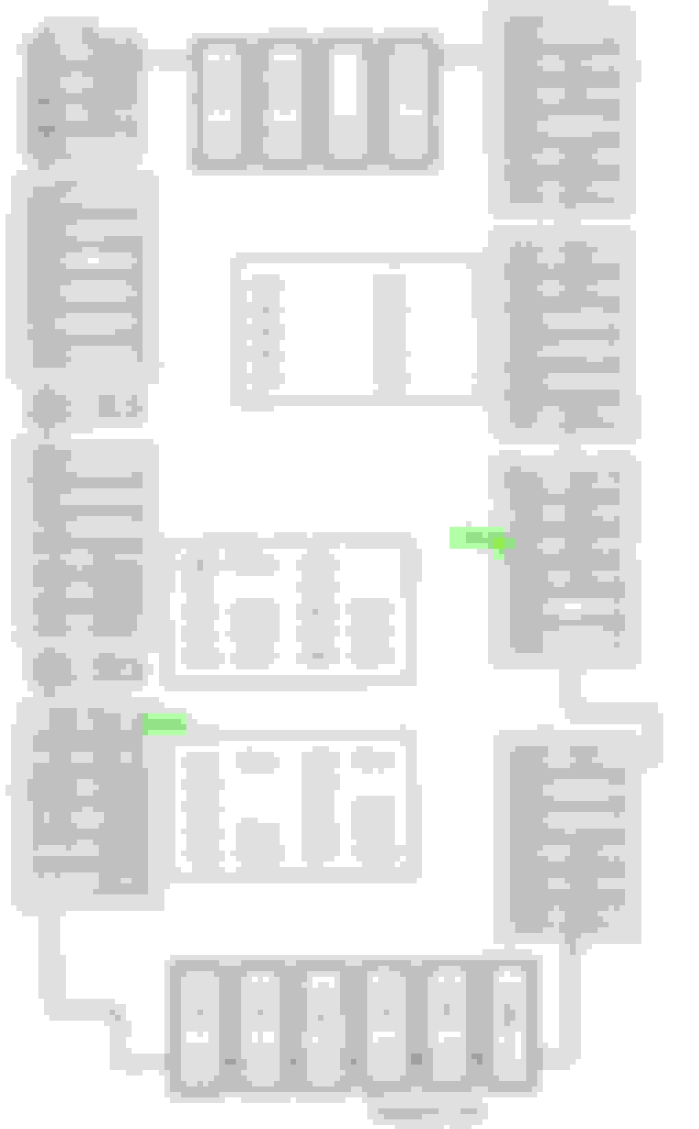
If I were to install dashcam via hardwired fuses, would those be the places to fuse tap for 2024 GLE 450?
(Type : Fuse Number - Function)
Constant : 406 - Door Functions
ACC : 457 - Socket 12V in center console
If they are incorrect, then could someone help me point to where ACC and Constant are? I have attached the GLE fuse allocation chart for reference.
I use the cargo 12v for ACC, but I don't see why you can't use the center console one.
As for constant power, I didn't connect mine and only use ACC power as source (to my battery pack). I would recommend getting a test light and check and see if the fuse remain on after car is off (remember you need to wait a bit since some fuse like those ACC one have a "delay" off)
That makes sense for 12v for ACC. Since you have a battery pack, do you recommend it? I didn't see the need at this moment to install battery pack at this time, unless it is a huge benefit.
If anyone else can confirm if 406 Door Functions are constant fuse or otherwise I would like to know what yall chose for constant, that would be helpful. I will forward that information to my installer the next time I visit for dashcam installation.
That makes sense for 12v for ACC. Since you have a battery pack, do you recommend it? I didn't see the need at this moment to install battery pack at this time, unless it is a huge benefit.
For me, personally I would like to keep the car 12v battery out of the equation (for the parking mode). Having the battery pack means you can still have the dashcam running while car is off without using the car battery. But you also have to factor in the battery size and install location if you do go with that route.
I have 2x battery pack installed, and with it fully charged (usually after 1 to 2 hours of driving), I can get around 30 hours of parking mode recording (I have constant recording on during parking mode). Wiring to the car battery will most likely give you a longer parking mode run time, but if the voltage cutoff doesn't work correctly (should be very low chance), you could run the car battery low.
This is how I wired the 12V plug in the back to the permanent live. Picture is from the rear fusebox. Feed comes from the left, the original fuse was on the right. Generally Mercedes seems to lay out its fuse boxes so there are "rails" with the same feed, so a rail with switched 12V, a rail with permanent 12V, ...
I just grabbed the multimeter and probed where there was 12V with the ignition off. I'm sure you can do the same in the other fuseboxes.
Incidentally, the manual is a book of lies, at least the English version. That took a bit of headscratching:
That's pretty funny. Looks like my 2024 GLE manual revision fixed that mistake.
Thank you for a photo of your rear fusebox. I noticed two wires tapping into the fuse in your photos. Is my assumptions correct?
Could you also please mark where you've mentioned the rails are located?
What you've marked is correct, in a way. My wiring isn't for a dashcam, just to change when the rear 12V plug is on, so I'm not actually tapping into the ACC, just providing that circuit with a constant 12V instead of the ACC switched 12V it originally had, through a separate fuse (the black box the red cables are going to).
If you wanted to tap into the ACC there, you'd use the left terminal for that fuse, as that's the power rail.
I did a bad job marking things here:
Yellow is the permanent rail, red the ACC. Those coloured holders you see clip onto the fusebox, the inside terminal is the power feed (what I call a rail) and the outside terminal goes to the circuit.
Where I tapped the permanent power is the same type of rail, but without one of the coloured holders (I guess only used on the GLS or something).
Where I tapped the permanent power is the same type of rail, but without one of the coloured holders (I guess only used on the GLS or something).
Thank you again for the quick response! If I read this correct, the permanent power rail where you've marked yellow is 443 to 448 in the manual. On mine it says reserve, so maybe it does not even have a use in GLS yet.
I understand your intent to provide permanent power to a fuse that was previously only on ACC. I think that is pretty clever solution for your use case.
Though I'mma cover all bases here just in case it is easier to tap into an existing fuse during my upcoming installation. So I will ask, if you or anyone else happen to know if any existing colored holders are the permanent power? That way, I can use something like add a fuse tap and tap into an existing fuse already in place.
I'm attaching my fuse box here again for reference.
Otherwise I think the multimeter solution will work as well. Just hoping to see if anyone else has the answer before I try to manually find one in a few days.

 01-02-2024 | 02:03 PM