When you click on links to various merchants on this site and make a purchase, this can result in this site earning a commission. Affiliate programs and affiliations include, but are not limited to, the eBay Partner Network.
350 SL, R230 - 300 SL, R129 - 1964 Corvette Sting Ray Sport Coupe - Porsche 911 Twin Turbo (sold)
FIXED.1992 300SL. The connector came off the wiper,combi relay so the wires are loose
Any here of my fellow forum members that have a schematic that shows where each of the wire goes where on the wiper/combination/N10 relay in the main fuse box on the left side in the engine?
Since the right side front park light stop working now and then i decided to take off the wiper relay to check if the contact points was dirty either on the connector or more likkely on the relay.
And off course when i pushed the tabs towards each other to loosen the large connetctor evertything popped off including the harness connector, Grrr...
And now this i must say irritates me quite a lot
I have tried to check relays for sale where the connector and a bit harness have been cut off but the colors of the wire does not match my car.
So now i am in desprat need of a wiring diagram/schematics that shows where each of the wires go on to the relay
I can off course try to put the connetor over the wires and try to put on 1 by 1 wire at the time, But if i mismatch any of the wires i am afraid i will ruin the relay.
Here is a coupe of pictures of the wire harness for the wiper relay on my car
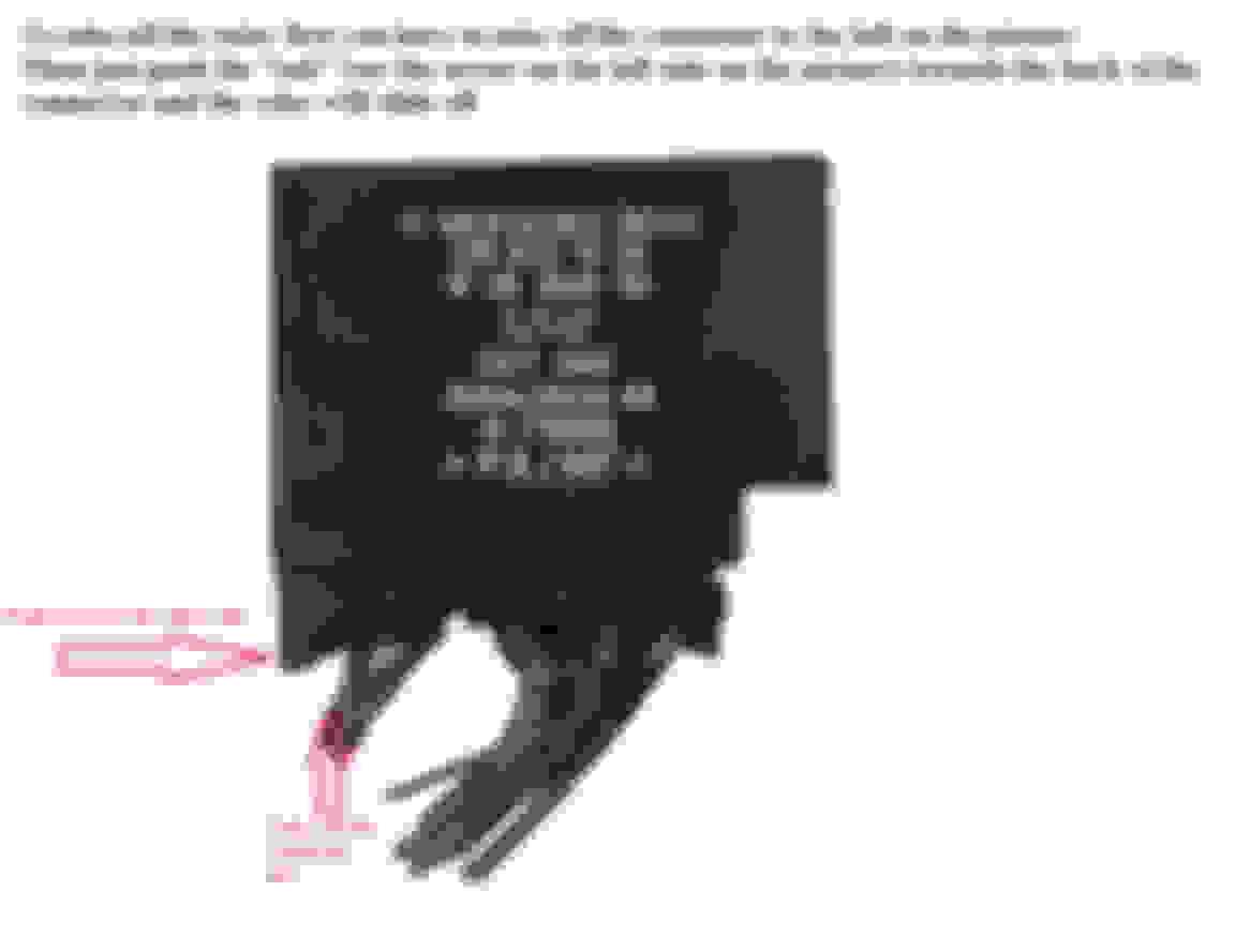
I am talking about the 129 820 10 26 relay (See the picture below)
The wires that goes in the connector seen from the left side of my 1992 300 SL (See the picture below)
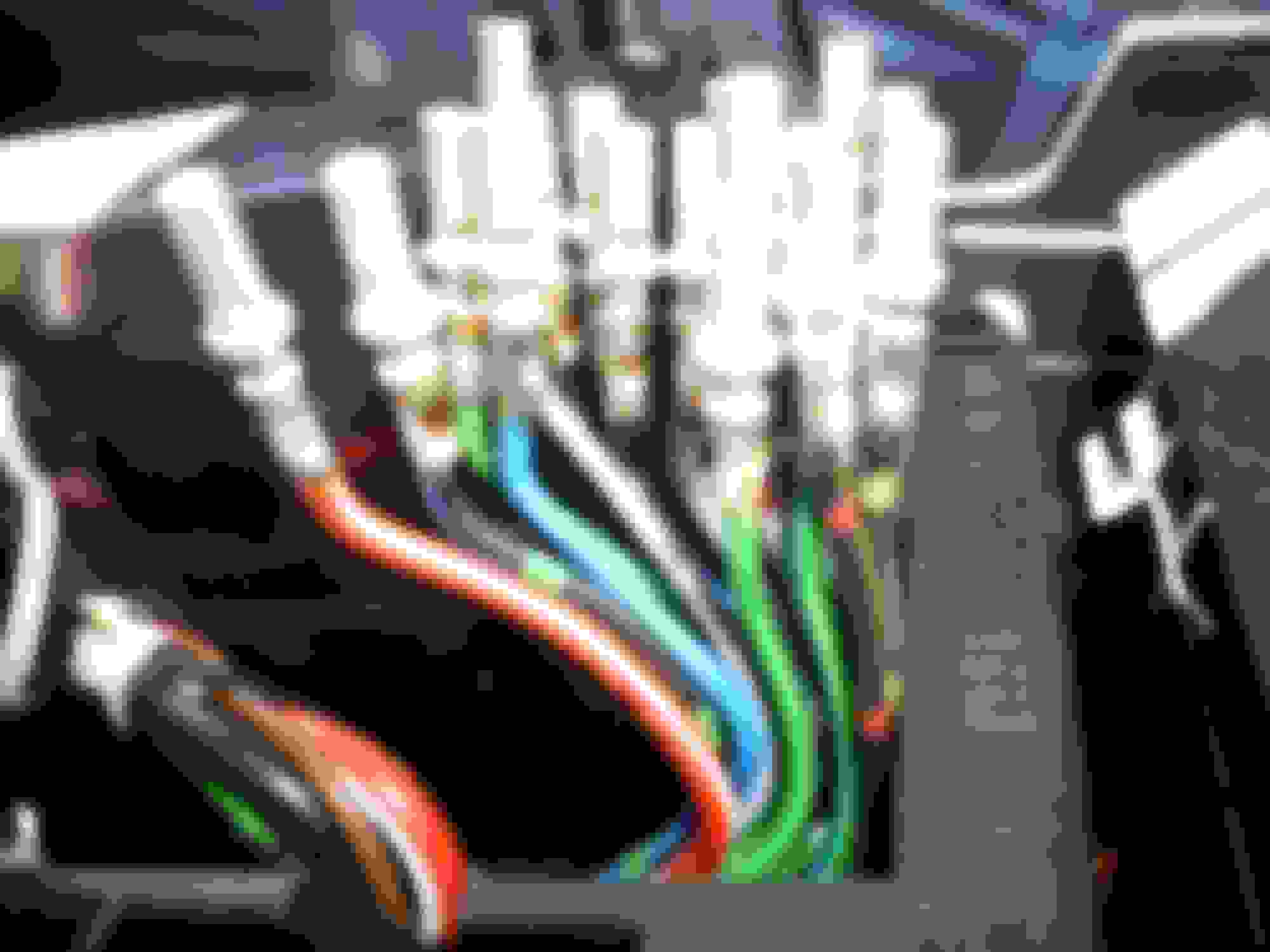
The wires that goes in the connector seen from the right front fender side of my 1992 300 SL (See the picture below)
The wires that goes in the connector seen from the front of my 1992 300 SL (See the picture below)
The wires that goes in the connector seen from the rear (windshield side) of my 1992 300 SL (See the picture below)
Last edited by TheSaint; Aug 20, 2022 at 06:05 PM.
I hope you have disconnected the battery already. It looks like the light control module.
I would look up the pinout of the module from the related wiring diagram. MB is very accurate with its colour coding.
If you share your VIN maybe someone shares the diagram or points you to the online source.
I have only the German version.
Cheers, Frank
350 SL, R230 - 300 SL, R129 - 1964 Corvette Sting Ray Sport Coupe - Porsche 911 Twin Turbo (sold)
Thanks for helping me out here
Took the small part of the 21 wire connector a threaded every wire thru it according to the diagram and locked the connector onto the small part of the connector
Put the turn signal, wiper, combination, N10 relay back on and everything is working as it is supposed to
I have made a drawing that shows which colour wire goes where on the 21 wire connector if anybody here needs it. I think it is the same for 1990-94 Mercedes SL, R129
Thanks a lot to Boat Waco for posting the link to the drawings. I downloaded the DFW files and convered them to PDF online To convert the drawings from DFW to PDF It is done in a couple of minutes
From this
To this
And finally to the finished result Everything is working as it is supposed to
Last edited by TheSaint; Aug 20, 2022 at 06:23 PM.
350 SL, R230 - 300 SL, R129 - 1964 Corvette Sting Ray Sport Coupe - Porsche 911 Twin Turbo (sold)
Why the wires came loose on my car is because i opened the "lock" for the wires since i thought it was a lock for sliding the relay off of the connector
So do not open the the part that the red arrow points towards if you are have any plans to take off your relay
Do not slide the part with the red arrow back! It is the part that locks all the wires to the connector! You can see on the picture how it "locks" the 2 "tabs" that sits on each side of the connector
Last edited by TheSaint; Aug 20, 2022 at 06:34 PM.
350 SL, R230 - 300 SL, R129 - 1964 Corvette Sting Ray Sport Coupe - Porsche 911 Twin Turbo (sold)
Frank_S500 i forgot to answer your first question, I did not take off the negative pole on the battery when taking off the relay.
But as soon as all the wires came loose off of the connector i took off the negative battery pole at once
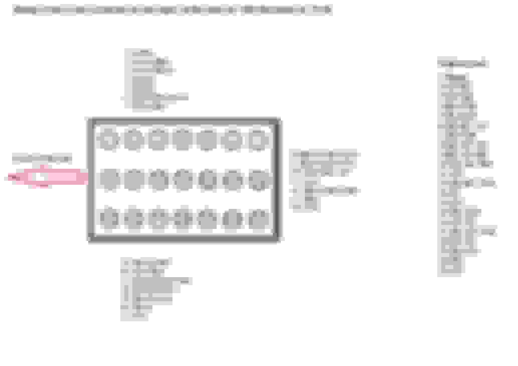
This drawing shows how the the wires is connected to the connector
To take the relay off take off the small connector first and slide the part with grooves on it (close to the red and white wire) towards the other side/the red arrow in the picture.
When you slide the connector toward the red arrow the 21 wire connector comes off
Do not push back the part of the connector that is marked with the red arrow since that is the part of the connector that locks the wires in place in the connecor. You can see how it locks the 2 tabs marked with yellow arrows (It is 2 tabs on each side of the connector)
Last edited by TheSaint; Aug 21, 2022 at 05:41 AM.
350 SL, R230 - 300 SL, R129 - 1964 Corvette Sting Ray Sport Coupe - Porsche 911 Twin Turbo (sold)
Frank_S500. Sorry for the late reply
First of all do not touch the part marked with 2 yellow arrows on the picture because that is what locks all of the wires in the connector. I did as you have read here
To get the relay off you first have to take off the connector with 6 wires (closest the fuses on the picture above)
Push the "tab" close to the red and white wire towards the "tab" on the other end of the connector and the relay will slide off
The relay with the most wires slides off of the connector when you push the "tab"
I hope this picture makes sense. Push the "tab" towards the other side of the connector. This is how i took off the relay
Last edited by TheSaint; Aug 21, 2022 at 05:17 PM.
Hi �saint� did the very same thing and have spent days trying to find a new/used intact unit. Then I came across your post and �bingo�. Sorry to be a pain but how do I find your colour coded diagram please. Many thanks. Adam
350 SL, R230 - 300 SL, R129 - 1964 Corvette Sting Ray Sport Coupe - Porsche 911 Twin Turbo (sold)
Originally Posted by Adam249
Hi “saint” did the very same thing and have spent days trying to find a new/used intact unit. Then I came across your post and “bingo”. Sorry to be a pain but how do I find your colour coded diagram please. Many thanks. Adam
Hi Adam249.
Which year is your SL?
Below is the color coded drawing i made for my 1992 SL, R129
I think this is for the 1990- 1993 SL, R129 and it might be different for a newer SL, R129 from 1994
I found every wired numbered from 1 to 21 on another Mercedes so thanks to the original poster
Anyway the drawing i made you can see below. I just post the drawing to help out but i do not know if it is correct for your car
I used several evenings over several weeks to find how the 21 pins is suppsed to be wired so i hope this helps you out
But i know where to find electric diagrams for the wiper, N10/2 connector
Note what it says below!
Mercedes list pin 11 as GY WH GN (Grey/White/Green) but on my car that wire was grey. Pin 11 had a grey wire on the original posters 1991 SL, R129 as well.
This is what i made the drawing from so thanks to davissl500 who posted this on another forum several years ago
The drawing is for a 1992 SL, R129. I can noy guarantee that this is correct so if any use this drawing they do it at their own risk
Last edited by TheSaint; Sep 14, 2022 at 11:43 AM.
Below is the color coded drawing i made for my 1992 SL, R129
I think this is for the 1990- 1993 SL, R129 and it might be different for a newer SL, R129 from 1994
I found every wired numbered from 1 to 21 on another Mercedes so thanks to the original poster
Anyway the drawing i made you can see below. I just post the drawing to help out but i do not know if it is correct for your car
I used several evenings over several weeks to find how the 21 pins is suppsed to be wired so i hope this helps you out
But i know where to find electric diagrams for the wiper, N10/2 connector
Note what it says below!
Mercedes list pin 11 as GY WH GN (Grey/White/Green) but on my car that wire was grey. Pin 11 had a grey wire on the original posters 1991 SL, R129 as well.
This is what i made the drawing from so thanks to davissl500 who posted this on another forum several years ago
The drawing is for a 1992 SL, R129. I can noy guarantee that this is correct so if any use this drawing they do it at their own risk
THANK YOU for this!! bought my 300sl and the previous owner changed the module out but turned all of the wiring to spaghetti and he wondered why it didn't work, so now i'm trying to sort it all out 😂
350 SL, R230 - 300 SL, R129 - 1964 Corvette Sting Ray Sport Coupe - Porsche 911 Twin Turbo (sold)
Hi
I hope this post helps you out
That for sure looks like spagetti for sure. I hope he have not cut a bunmch of wires.
I guess the instrument panel/gauges are lit up like a christmas tree on you car if you have not sorted it oout already
Take off the battery before you start and if your car is within the years i wrote just use the diagram and put on 1 wire at the time.
Since i was standing by the side of the left front fender i did the middle line of the wire connectors first, so the the line towards the right front fender and then the line with 6 wires towards the left fender last.
If you do the middle line last it will be difficult ti "thread" the wires in among all of the other wires.
When you have placed alll the wires correct lock the connector with the locking part that sits on the connector (There is a picture of the part of the connector that holds the wireslocked to the connector earlier in this post)
Yeah no lol, There were many different size torpedo fuses put everywhere so i have those put to factory spec and now the headlight washer pump wants to run 24/7 and the driver turn signal bulb and tail light is dead so gotta figure that out, do you by chance know the connector order for the connector closest to the front of the car on the module? that is also missing and turned into spaghetti or is that part of your diagram?
vvv
Last edited by 92-300sl; Feb 17, 2023 at 01:14 PM.
Mercedes SLR McLaren 722 S Is Extremely Rare Example Modified by McLaren
Slideshow: A one-of-one U.S.-spec Mercedes-Benz SLR McLaren Roadster became even rarer after a factory-backed transformation at McLaren's headquarters.


 or is that part of your diagram?