
The mother load of pic for catch can install


Thread Starter
MBWorld Fanatic!


Joined: Dec 2011
Posts: 1,645
Likes: 13
From: tampa florida
19 f-150 limited (w/raptor engine) 06 e55,81SC Targa,08 CLK63 BLK,91 E34 M5
The mother load of pic for catch can install
First before you aggravate yourself go out and get these hose barb T's

THE 1/2" is for the driver side
And the 3/8 is for the passenger side
START Driver side first from the valve cover

Take off the male to male black hose barb close to the throttle body and put the T there and the 1/2" hose going to catch can


This is where the other end of the half inch hose will be snaked in through along the brake lines


Make sure to plug the driver side back in
The passenger side now
Your to going have to take off the surge tank to make it easy to work
Remove the black hose from the valve cover connected to the valve cover right beside the surge tank that is where the 3/8 T and the little 1" hose that came with the kit will go.
Use the new 3/8 T and snip one groove off of the tips. On opposite sides only cause it is to long. do not snip anything off the hose going to the catch can.
Put the little 1" long hose into the pass valve cover part then add the T and put the other side (black hose) coming from the under the throttle body.


Then connect the 3/8 hose that they gave you snake it into here you need a dremell to cut a hole make sure to lift the rubber strip to get it out


Make sure to take off the cabin filter box so you can install the hosees from both sides

With the cabin filter back in


THE 1/2" is for the driver side
And the 3/8 is for the passenger side
START Driver side first from the valve cover
Take off the male to male black hose barb close to the throttle body and put the T there and the 1/2" hose going to catch can
This is where the other end of the half inch hose will be snaked in through along the brake lines
Make sure to plug the driver side back in
The passenger side now
Your to going have to take off the surge tank to make it easy to work
Remove the black hose from the valve cover connected to the valve cover right beside the surge tank that is where the 3/8 T and the little 1" hose that came with the kit will go.
Use the new 3/8 T and snip one groove off of the tips. On opposite sides only cause it is to long. do not snip anything off the hose going to the catch can.
Put the little 1" long hose into the pass valve cover part then add the T and put the other side (black hose) coming from the under the throttle body.
Then connect the 3/8 hose that they gave you snake it into here you need a dremell to cut a hole make sure to lift the rubber strip to get it out
Make sure to take off the cabin filter box so you can install the hosees from both sides
With the cabin filter back in


Thread Starter
MBWorld Fanatic!
Joined: Dec 2011
Posts: 1,645
Likes: 13
From: tampa florida
19 f-150 limited (w/raptor engine) 06 e55,81SC Targa,08 CLK63 BLK,91 E34 M5
Thank you all for the complements.
I will help you on fri berti00 to install the catch can if it does not rain
I will help you on fri berti00 to install the catch can if it does not rain
Trending Topics
MBWorld Fanatic!
Joined: Apr 2009
Posts: 1,255
Likes: 5
E55
Nice write up and pics. 
Please don't take this next part the wrong way as my intentions are well intended. By the looks of it, you might need to reconfigure the hose arrangement. I don't have this kit, nor have I installed one, but I would think that by T'ing the lines the way you did, the oil vapors are still not going to collect in the catch can. I could explain further if you want.
Hope I'm helping....and don't shoot the messenger.
Peace.

MBWorld Fanatic!
Joined: Mar 2011
Posts: 1,879
Likes: 22
From: Orange County, CA.
one car at a time
Nice write up and pics.
Please don't take this next part the wrong way as my intentions are well intended. By the looks of it, you might need to reconfigure the hose arrangement. I don't have this kit, nor have I installed one, but I would think that by T'ing the lines the way you did, the oil vapors are still not going to collect in the catch can. I could explain further if you want.
Hope I'm helping....and don't shoot the messenger.
Peace.
FWIW, I prefer either a two can setup or a can with two in and one out.... DC3s for me

Thread Starter
MBWorld Fanatic!
Joined: Dec 2011
Posts: 1,645
Likes: 13
From: tampa florida
19 f-150 limited (w/raptor engine) 06 e55,81SC Targa,08 CLK63 BLK,91 E34 M5
Nice write up and pics.
Please don't take this next part the wrong way as my intentions are well intended. By the looks of it, you might need to reconfigure the hose arrangement. I don't have this kit, nor have I installed one, but I would think that by T'ing the lines the way you did, the oil vapors are still not going to collect in the catch can. I could explain further if you want.
Hope I'm helping....and don't shoot the messenger.
Peace.
Please don't take this next part the wrong way as my intentions are well intended. By the looks of it, you might need to reconfigure the hose arrangement. I don't have this kit, nor have I installed one, but I would think that by T'ing the lines the way you did, the oil vapors are still not going to collect in the catch can. I could explain further if you want.
Hope I'm helping....and don't shoot the messenger.
Peace.
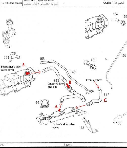
A to A is where your supposed to T it off from and install the catch can in between the the two A hoses.
but can you please elaborate more? I completely get what your saying about routing each side individually into it own catch can prob would be the best way to really go about it. Is that what your saying right cause it does make more sense.
Last edited by Manuyc; Aug 23, 2012 at 08:46 AM.
Thread Starter
MBWorld Fanatic!
Joined: Dec 2011
Posts: 1,645
Likes: 13
From: tampa florida
19 f-150 limited (w/raptor engine) 06 e55,81SC Targa,08 CLK63 BLK,91 E34 M5
What he is saying make a lot of sense one catch can will catch some vapors but not all you will need one catch can on each side before it enters the throttle body. The setup now is just t'ed off instead of completely cutting it off from the throttle body.
MBWorld Fanatic!
Joined: Mar 2011
Posts: 1,879
Likes: 22
From: Orange County, CA.
one car at a time
From valve cover port A to inlet of catch can (new, non-OEM line), then from outlet of catch can to OEM line A (use a male to male connector to connect the non-OEM line to the factory line). This routing will require you have two cans since the FTB only has one inlet.
OR you can do as follows :
From valve cover As run two new non-OEM lines with an inline check valve and then connect to a T (tee) from the T run a non-Oem line to the catch can inlet. From the catch can outlet run a line to port B on the throttle body. (Just save the factory lines.)
For what it is worth, I would also install an inline filter with line C and see if you get any buildup. If so, then I would add another can or just change the inline filter periodically.
I hope this helps.
Last edited by cij911; Aug 23, 2012 at 08:56 AM.
Thread Starter
MBWorld Fanatic!
Joined: Dec 2011
Posts: 1,645
Likes: 13
From: tampa florida
19 f-150 limited (w/raptor engine) 06 e55,81SC Targa,08 CLK63 BLK,91 E34 M5
I think running one catch from each side will be the best way.
Since a check valve in running into two lines might get stuck or not enough flow at WOT
Since a check valve in running into two lines might get stuck or not enough flow at WOT
MBWorld Fanatic!
Joined: Apr 2009
Posts: 1,255
Likes: 5
E55
^ There ya go, the second arrangement for your setup. Not sure why a check valve would be needed though.
Manuyc, port B is the vacuum port and needs to be plumbed directly to the catch can. The other port on the catch can can be T'd to the valve cover ports. The idea is for all the vapors to be pulled through the catch can. As for which port on the catch can should go where, the port with the filter should go toward the valve covers. The filter will then collect the vapors and drip into the catch can.
Manuyc, port B is the vacuum port and needs to be plumbed directly to the catch can. The other port on the catch can can be T'd to the valve cover ports. The idea is for all the vapors to be pulled through the catch can. As for which port on the catch can should go where, the port with the filter should go toward the valve covers. The filter will then collect the vapors and drip into the catch can.
MBWorld Fanatic!
Joined: Mar 2011
Posts: 1,879
Likes: 22
From: Orange County, CA.
one car at a time
The nice thing about two cans is you can generally make the setup cleaner (less lines wrapping around the engine). That said, sometimes find a good spot to mount two cans is not an option.
Great write-up BTW, just make sure you edit the pictures and directions, so that folks that follow your post don't install their cans incorrectly.

Thread Starter
MBWorld Fanatic!
Joined: Dec 2011
Posts: 1,645
Likes: 13
From: tampa florida
19 f-150 limited (w/raptor engine) 06 e55,81SC Targa,08 CLK63 BLK,91 E34 M5
^ There ya go, the second arrangement for your setup. Not sure why a check valve would be needed though.
Manuyc, port B is the vacuum port and needs to be plumbed directly to the catch can. The other port on the catch can can be T'd to the valve cover ports. The idea is for all the vapors to be pulled through the catch can. As for which port on the catch can should go where, the port with the filter should go toward the valve covers. The filter will then collect the vapors and drip into the catch can.
Manuyc, port B is the vacuum port and needs to be plumbed directly to the catch can. The other port on the catch can can be T'd to the valve cover ports. The idea is for all the vapors to be pulled through the catch can. As for which port on the catch can should go where, the port with the filter should go toward the valve covers. The filter will then collect the vapors and drip into the catch can.
AND 
Thread Starter
MBWorld Fanatic!
Joined: Dec 2011
Posts: 1,645
Likes: 13
From: tampa florida
19 f-150 limited (w/raptor engine) 06 e55,81SC Targa,08 CLK63 BLK,91 E34 M5
All I can say is I was following instruction diagram from kit prior install.
But cij911 you help make it more clear for and I hope it helps anyone else that is going to install a catch can. Cause there isn't one here much info on it for e55
Thank you again
But cij911 you help make it more clear for and I hope it helps anyone else that is going to install a catch can. Cause there isn't one here much info on it for e55
Thank you again

Member
Joined: Oct 2010
Posts: 225
Likes: 0
From: NY
Escalade ESV Platinum (Blue Chip), 2004 E55 (SOLD) , 2001 Brabus CL600 (SOLD), 1997 E420 (SOLD)
Im about to install my new ADD-W1 Catch can but none of these pics are being displayed. It says picture has been moved or removed. Anyone have another DIY with pics? I have my serge tanks off to get powder coated so I figured i get this done before I reinstall them. Any help would be appreciated.
Super Member
Joined: Mar 2013
Posts: 602
Likes: 3
From: America
04 E55 AMG
Go to the DIY sticky then look at the very last post DIY sticky thread addition, then go into that and you will see many DIYs including a catch can install.https://mbworld.org/forums/w211-amg/...reat-info.html herehttps://mbworld.org/forums/w211-amg/...-addition.html
https://mbworld.org/forums/w211-amg/...tallation.html
You have to click on the links
https://mbworld.org/forums/w211-amg/...tallation.html
You have to click on the links
Last edited by MAN55LE; Apr 27, 2014 at 10:26 PM.
Member
Joined: Oct 2010
Posts: 225
Likes: 0
From: NY
Escalade ESV Platinum (Blue Chip), 2004 E55 (SOLD) , 2001 Brabus CL600 (SOLD), 1997 E420 (SOLD)
Go to the DIY sticky then look at the very last post DIY sticky thread addition, then go into that and you will see many DIYs including a catch can install.https://mbworld.org/forums/w211-amg/...reat-info.html herehttps://mbworld.org/forums/w211-amg/...-addition.html
https://mbworld.org/forums/w211-amg/...tallation.html
You have to click on the links
https://mbworld.org/forums/w211-amg/...tallation.html
You have to click on the links


