When you click on links to various merchants on this site and make a purchase, this can result in this site earning a commission. Affiliate programs and affiliations include, but are not limited to, the eBay Partner Network.
Sweet! Looks much newer with that one. Was thinking about doing the same for my 221 .
I believe there is an aftermarket interface that may be plug and play for that model. I'm not sure though... Contact these guys, they may be of help... https://navi-expert.com/
All controls working. E63 Guage faceplate. Alpine head unit with the lot... Happy Days!
03 E55 with Alpine head unit and updated Wheel. 03 E55 with Alpine head unit and updated Wheel.
Can anyone share the installation manual/instructions on how to install the latest steering wheel in the w211?
I got the steering but confused over the connections as the plugs are different (airbag and steering sensor...) and i did not receive the manual.
Can anyone share the installation manual/instructions on how to install the latest steering wheel in the w211? I got the steering but confused over the connections as the plugs are different (airbag and steering sensor...) and i did not receive the manual.
Unfortunately there is no procedural manual for this upgrade.
This is a custom mod that I done from home.
I'm quite sure there are some businesses out there that could help you unless you want to try and do it yourself.
I'm happy to tell you the procedure but you would need some electronic and fabrication skills...
Originally Posted by maliciousdxb
Can anyone share the installation manual/instructions on how to install the latest steering wheel in the w211?
I got the steering but confused over the connections as the plugs are different (airbag and steering sensor...) and i did not receive the manual.
Thanks a lot! Fabrication and electronic skills we have knowledge we don't have... Can you message me or send me some instructions? Which wires goes where etc...
Thanks in advance!
Thanks a lot! Fabrication and electronic skills we have knowledge we don't have... Can you message me or send me some instructions? Which wires goes where etc...
Thanks in advance!
Here you go...
I can�t give you all the details as I never recorded the process, but I can give you the idea and the method behind the conversion. This is only my way, but I�m sure this solution may be simplified, improved, or updated by others.
Theory: Use the original stock steering wheel electronics and transfer them into an updated wheel. This includes Ambient lighting, Switches, Airbag, and Paddle shift controls.
Practice Items:
� Making a shroud cover to extend over the steering column.
� Paddle shift.
� Wiring the new Controls.
� Ambient lighting.
� Airbag.
� Horn.
� Indicator Lever.
Shroud: This style wheel will psychically fit the W211 steering splined shaft. You need to cut some material from the rear spline area, see photo� Do not cut any of the steel spline, just the alloy portion. Once this is done there is enough spline space and thread to mount the wheel. Next, I found some PVC Pipe that would fit around the plastic steering column and cut it to the length that I wanted it to extend it out. This was then mounted on the lathe to be squared and have the edges rounded off. I then used 3M Wrap film to cover it but not to extend over the edge that will be mounted to the wheel. The shroud was then squared and lightly clamped to the wheel. I then used JB Weld epoxy on the wheel inside to join the 2 bits together� https://www.amazon.com.au/J-B-Weld-8.../dp/B0006O1ICE Job 1 done.
Paddle shifts: The w211�s circuit uses 2 pins only to denote both switch�s status, either Up, Down, and Normal.The left switch is N.O� When closed it shorts a diode altering the output. The Right switch is N.C with a resistor hanging across it. The problem is that the new style paddles are both N.O. That's OK for the left but not obviously for the right. Solution: Wire in a really small 12v micro relay then use the right N.O paddle to trip it. Tap the 12v source from the stock LIN bus connector. Make sure you put a protection diode across the power input to prevent current backflow. IN-4004 should do the job. Clean up the harness to neatly fit.
L&R Controls: This is the hairy part� only due to how small the electronics are in the new control units. I�ll get to this part later�
The w211 L and R units are different internally. When we remove both switches from the old wheel you will notice only 1 of them has the LIN bus control chip located inside which is wired to the clock spring. I believe it's the right unit� (Depending on variant configurations, country codes, etc�) For ****s and gigs let's just say the Right unit for now.
Theory of operation: All switches and LED�s have a common (+) Positive. So we only need to tap a separate (-) Negative to all switches, 4 each side and 1 LED (-) Negative each divided to each side from the LIN bus PCB. The L switches will need a resistor wired in series for each switch, I think it was 3R3, just check with a meter on the old board� All switches are N.O.
Next, First, choose from the new controls which switches you want to assign the functions from the old wheel� For example, I assigned the Phone answer and hang up to the same functions� Next, (the fun bit) get the new PCB�s and identify and isolate each track to each switch you want to use. It is so small to see, so I used a Mantis microscope and a continuity tester to find each track. I also cut and removed every component connected to them. Once all this was done, I soldered a common (+) wire to every LED and switch on both PCB�s. Now we have our positive common. Next, solder one wire for each switch. Link all the LED�s to a common (-)� Do this for both sides. You should have 6 wires on each side. Comm (+), Comm LED (-), SW1, SW2, SW3 AND SW4�
Next, prep the stock LIN bus PCB. (1) Remove all led resistors. (2) Cut all the copper pins to the connectors as we need to flatten the PCB out to fit inside the wheel. (3) Solder the 6 wires from all the switches to their appropriate locations which you traced out and noted earlier�
Ambient lighting: LED�s require resistors to be connected� The final brightness was fixed with a resistor value, this value was determined by reassembling the new controls and hooking a power supply set to 13vdc then trying some different values in the dark to obtain the brightness desired. I used 1watt resistors. I can�t remember the actual values but they were different for both sides as one side drew more current than the other to balance out the brightness. On another note, use a thinner gauge wire for everything so the harness will fit neater inside the wheel. Stitch all the wires up and go test the loose bits in the car. Hook it up and try all the functions and look at the lighting. (Do this in the dark to compare with the factory ambient lighting)
Air Bag: There are 2 styles, 1 Plug, and 2 Plugs. They both look the same from the outside but function differently. This is due to variant coding and international Safety codes� Single plug, single detonation� Twin plugs, Lower and higher power detonation. Check your configuration and source the bag to your spec. In my case, I had a single plug airbag with 2 plugs hanging out of my column. I put a resistor across the unused pre-detonation plug to prevent error codes. I don�t remember the value but it�s a common mod so just google it. After you put the wheel back together, remember to clear any SRS errors with DAS.
Horn: Connect the horn circuit to the one that came with the wheel. Gut out the electronics and tap the switches. Cut the plastic edges on the box to fit the LIN bus PCB in there.
Indicator Lever: This will be way too close to the paddle and will touch your fingers. Work out how far you want it back. Do not try and bend it while it�s mounted on the column, or you will uk it up� Remove the indicator assembly then disassemble the arm and switch mech. Mount the arm nicely in a vise with wood or something soft and bend it into the desired position. The lever has a metal tube inside the plastic. Reassemble and install�
Put it all back together and test�
That's it, Done� Best of luck!
Remove only the cast alloy around the spline sleeve...
Another way to speed up the control switch procedure is to make up a set of custom PCB's to retrofit into the new housings with edge connectors and lighting etc... would almost make it plug and play...
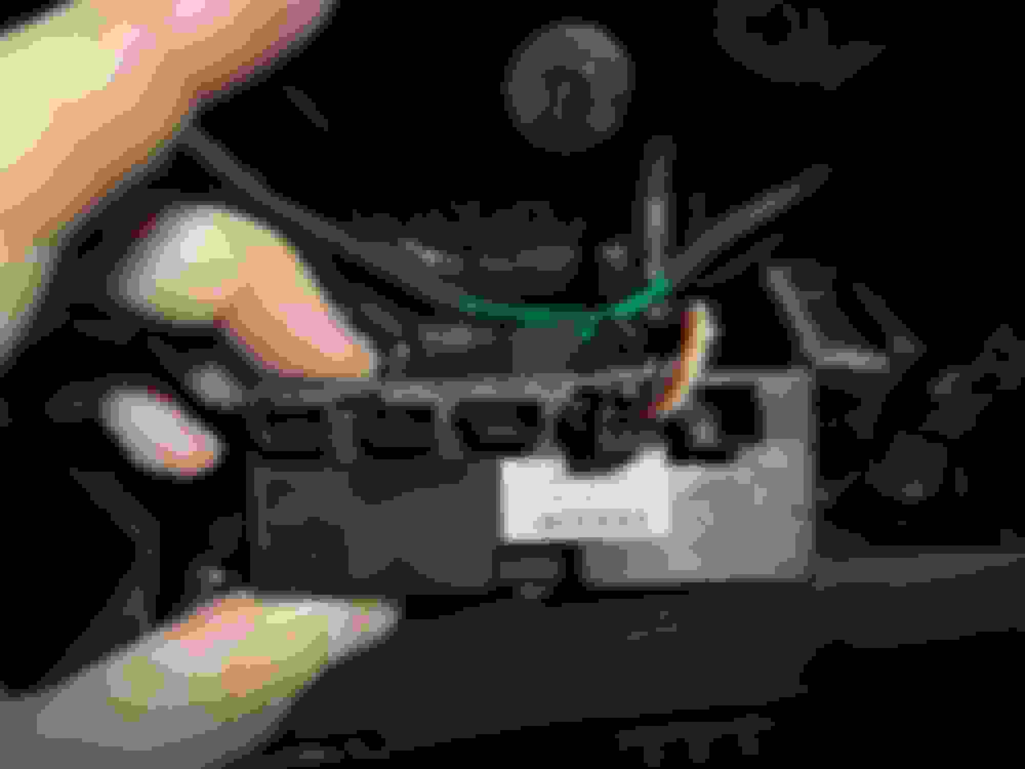
Thanks for the detailed explanation. I attached the pics below, what the steering has and what comes out of the column.
By the way, it comes with the small pcb box, i believe that is the convertor already programmed for the controls. As they asked for the VIN number during the fabrication for programming purposes...
Last edited by maliciousdxb; Jan 19, 2021 at 12:21 AM.
Reason: added more info
I�m looking to fit a newer style steering wheel to my facelift w211 Cdi 2006. The is totally standard and very low mileage. I would really like to remove the existing wheel and just fit the new one without chopping the car. So if at any stage I can put the old wheel back on. Is this possible and what sort of money am I looking t to do this? I doesn�t have to be an amg wheel I think a w205 would like just as good. Would be great full for any advice.
Thanks for the detailed explanation. I attached the pics below, what the steering has and what comes out of the column.
By the way, it comes with the small pcb box, i believe that is the convertor already programmed for the controls. As they asked for the VIN number during the fabrication for programming purposes...
could you share where you found these images or a website where this conversion is being sold? I'd love to upgrade my wheel to a newer wheel.
They fitted the wheel, and connections as well, but unfortunately there is no lights on the buttons and no response from the buttons at all.
Also, the workshop has newer model of the E class, that fits plug and play with the connectors supplied on the wheel and its the same situation.
So i am guessing the wheel is not programed or something is not done properly from the manufacturer.
You mentioned that you sent your VIN number before ordering? If so, you may need to send back the LIN bus decoder and have it tested or reprogramed. Have you contacted RU Carbon for their advice?
Paddle shifts: The w211�s circuit uses 2 pins only to denote both switch�s status, either Up, Down, and Normal.The left switch is N.O� When closed it shorts a diode altering the output. The Right switch is N.C with a resistor hanging across it. The problem is that the new style paddles are both N.O. That's OK for the left but not obviously for the right. Solution: Wire in a really small 12v micro relay then use the right N.O paddle to trip it. Tap the 12v source from the stock LIN bus connector. Make sure you put a protection diode across the power input to prevent current backflow. IN-4004 should do the job. Clean up the harness to neatly fit.
So do you remember the resistance across the right NC switch? Or is it not so important?
Thanks.
So do you remember the resistance across the right NC switch? Or is it not so important?
Thanks.
It's important or it will not work. That's just how the circuit was designed.
The resistor is located inside the old stock switches, soldered to the PCB.
I don't remember the value as I just used the PCBs in the loom with the added relay.
The other switch is N.O with a diode hanging across it, so there are 3 states given:
Normal = Diode loop. Idle state.
Left Gear = Short the diode, N.C Circuit.
Right Gear = N.O, Resistance with Diode. 03 E55 Steering Wheel Up Down Shift schematic.
Thanks. Probably not the same in my car though as it is a MY 2006... Didnt really think about that until now so I will probably have to check my own shift buttons 🤔
Hope its plug and play!
Wow! It needs a "Remove before flight" red tag! I'm curious how difficult is a slow turn when you normally have to turn the steering wheels like 2.5 times?
Look up RUCARBON. Those guys had been retrofitting and customizing wheels for a little while and might be able to help you. I've seen E55's with 2018-2020 wheels, but you lose some of the features( cruise control is one of them, I think)
Originally Posted by schnell!
I think that I've read through all of the steering wheel threads... and haven't found what I'm looking for. What is the most recent steering wheel that anyone has retrofit into an E55? I absolutely love the wheel in our '13 E350 and now must have one in the older car as well. I realize that there would be some wiring issues with the shift paddles and that all of the buttons may not work. Any thoughts?
Purchased a new wheel and the control module. I thought this was all supposed to be plug and play but it�s not working out that way.
The new wheel has 2 pin connectors and the module has 3 pin connection. Also the left side isn�t long enough to reach the module.
The seller is telling me to cut the connectors off my orig wheel and use them with the orig harness to plug into the module. They can�t tell me which plug on the module it should then plug in.
I am lost and need some help please. New wheel connections New module no place to plug in Left side paddle wire not long enough to reach Orig button connectors Orig harness
I have make this conversion in many w211,w219,r230,r171,w164 with 2018 AMG steering wheel or also 2013 AMG steering wheel
I can send steering wheel worldwide ready for installation
more info in pm or email or WhatsApp app
John
Do you have an option for 2008 W211 E350 ? and cost , I am in Sydney
Mercedes SLR McLaren 722 S Is Extremely Rare Example Modified by McLaren
Slideshow: A one-of-one U.S.-spec Mercedes-Benz SLR McLaren Roadster became even rarer after a factory-backed transformation at McLaren's headquarters.


 knowledge we don't have... Can you message me or send me some instructions? Which wires goes where etc...


 I'm curious how difficult is a slow turn when you normally have to turn the steering wheels like 2.5 times?