When you click on links to various merchants on this site and make a purchase, this can result in this site earning a commission. Affiliate programs and affiliations include, but are not limited to, the eBay Partner Network.
For those of you with trunk tank. I need some help with the installation process. The summer is around the corner. I've bought this 5 gallon tank since last year, but never got around to install it.
My questions are: can they be installed along with the split cooling system since I have that right now, or will I have to get rid of the split system, returning it back to stock flow system.
Any suggestions, flow diagrams, step by step instructions will be appreciated.
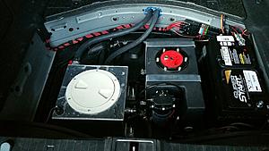
I ran my hoses a little different to the rest who go over the subframe, the position of my battery had a little influence on this because in mine (RHD) the battery is closest to the rear seat which is where a lot of the other guys drill their holes and route their hoses
I ran my hoses through the floor pan in the trunk and up over ~2" of exhaust by the right rear muffler (exhaust was exhaust wrapped and then heat wrapped over the top and the hose in that area was heat wrapped)
I then went up OVER the rear wheel arch, there is actually plenty of free room there and then down through the bottom right floor pan just like everyone else
This then runs up to the front up OVER the front wheel arch and tucks nicely in the upper fender area, from here down to the pump area where all connections are fitted
Here is a basic "pre school" diagram of my setup
I needed just under 50ft of 3/4" hose for this route
** The images below were while I was test fitting the routing in the rear wheel arch, this is how I ran the hose in the rear but how I secured it may differ slightly from the images
Front Rear Wheel Arch to chassis underpanel
Rear Evap Area - NOTE: - This was before heavily wrapping the area of exhaust and hoses with exhaust wrap and reflective heat padding etc
Upper Rear Wheel Arch
Split Cooling Blocked Off
I run 20" wheels daily and am lowered with a tuck, there is still plenty of clearance from the hose-tyre even with travel
I run 17" 275 Mickey Thompson Radials at the track and have had no issues with the tyre-hose location on launch etc at the track
The rear pump was wired into the switched 15amp fuse in the rear which is about the 4th fuse down from the top using a "piggyback fuse holder and extensions"
The front pump was wired to the 40amp window wiper fuse in the front using another "piggyback fuse holder"
Last edited by menace2sobriety; 05-01-2016 at 06:35 PM.
Just don't do what the previous owner of my car did. he ran the hoses up and over the passenger rear CV boot. Destroyed the boot because the boot was spinning on the hose. The hose sprung a small leak and the coolant ran partially dry.
Will probably just take it to the performance shop. Don't have all this patient. Any idea how much it will cost for the install?
Save your cash and just do it...
Took me ~12hrs on axle stands - this was extended due to my dremel and other cutting tools not working to cut the split circuit clamps off, (by other cutting tools I mean) my wifes gardening shears didn't do the trick either and I had to go out and buy something to block it off with as shown in the bottom image, 20% of that time while doing it outside it was raining which certainly delayed me a bit, dedicated or just stupid....I'd say the latter, but it is all done, I know every area it runs, where its all wired, I know it was all done without issues without any hack fixes/workarounds, if any issues arise I will know exactly where to look and how to handle it, many well deserved beers drunk afterwards
On a hoist I would possibly expect to get charged ~6-8 hours labour if they have done it before, not including any additional parts they may need in the process
Definitely not a difficult task, just time consuming.
Results with ice are incredible compared to pre tank conditions.
I used a bore bit to make two holes for the hoses. I found out that it's a double-walled bulkhead there, which messed up my idea of using these really sweet grommets I found for the passthrough.
This exit point was high enough that the hoses are completely clear of any moving suspension pieces and has suitable clearance from the exhaust. I fed the hose up from the bottom and pulled them through the holes, then routed the rest alongside the brake line. If you drop that passenger side undercarriage panel (easy), you'll see the brake line. Then I routed it up through the front wheel well and down to the i/c pump. I can't even see the hoses from under the car.
Note: the '03 & '04 have the battery mounted in the middle, so this may not work.
Finally installed my trunk tank last week at the performance shop. Connection is from the trunk >HE > front pump > IC and back to the trunk. The performance shop said they don't need to cap off the split cooling system.
I open up the split cooling reservoir, and noticed that it was emptied. Pour some water inside, and quickly disappeared. Finally, noticed that it was going to the rear tank. Is this good or bad?
I thought so as well, that the flow route was wrong. Will have to take it back to the shop.
Should go
TANK > IC > HE > FRONT PUMP > TANK
You say you were filling your split reservoir and it was going to the tank? - If you have a BMW res up front dropkick that pos to the kerb
The rear tank is your fill point now
* edit * - The reason you want it to go from the tank to the IC is so that you can fill it with ice and have super chilled water flowing from the tank directly to the IC, IF.... it has to bypass through the HE the way you currently have it then it will effectively be heating it up closer to ambient on its way to the IC
Last edited by menace2sobriety; 07-13-2016 at 08:17 PM.
With the tank system no reservoir required, I have space under my hood and considering a secondary reservoir because it will be the highest point for air bleed off,
I really don't see any difference in the intake temp. Compared to what others are claiming. Cruising temp is between 12~17 above ambient, and 15~25 WOT. The split system is pressurized as the performance shop showed me.
There are two big benefits with the trunk tank. One is faster IAT recovery between runs with the ability to do more runs before heatsoaking the system. The other is adding ice to the tank which will lower your IATs until all the ice is melted.
There are two big benefits with the trunk tank. One is faster IAT recovery between runs with the ability to do more runs before heatsoaking the system. The other is adding ice to the tank which will lower your IATs until all the ice is melted.
Is trunk tank good enough for a clutchless pulley, or one need more cooling to go with that?
If you've split your system from the engine coolant loop, addressed the stock pump, and added a bigger heat exchanger, then a trunk tank is good enough.
It should bleed from the highest point in the system.
If your pumps are tandem start with the lower pump start upper pump and open the relief on the intercooler.
When I decide on a tank, I am going to get coil of aluminum or copper and custom bend the tubing. Insulation is important to collect the BTU enhancement. When the I/O pipes are touching like in some of the photos convection transfer heat occurs.
The thermal wrap is a good idea to keep external heat sources away from the I/O pipes as well.
Best, Gator
So the system needs bleeding? through the intercooler pipe valve?

 04-29-2016 | 01:08 PM


 Save your cash and just do it...
 and I had to go out and buy something to block it off with as shown in the bottom image, 20% of that time while doing it outside it was raining which certainly delayed me a bit, dedicated or just stupid....I'd say the latter, but it is all done, I know every area it runs, where its all wired, I know it was all done without issues without any hack fixes/workarounds, if any issues arise I will know exactly where to look and how to handle it, many well deserved beers drunk afterwards