When you click on links to various merchants on this site and make a purchase, this can result in this site earning a commission. Affiliate programs and affiliations include, but are not limited to, the eBay Partner Network.
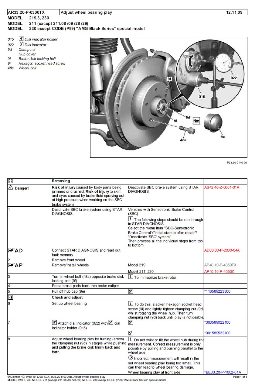
Step 1) Jack up and support front end of vehicle properly with jack stands then remove wheel:
Step 2) Remove the dust cap using whatever method and tools necessary. I used the end of a rasp file and hammered along the edge while rotating it around and tapping at various spots until it came loose.
Step 3) Use a 5mm allen wrench to loosen the retaining nut.
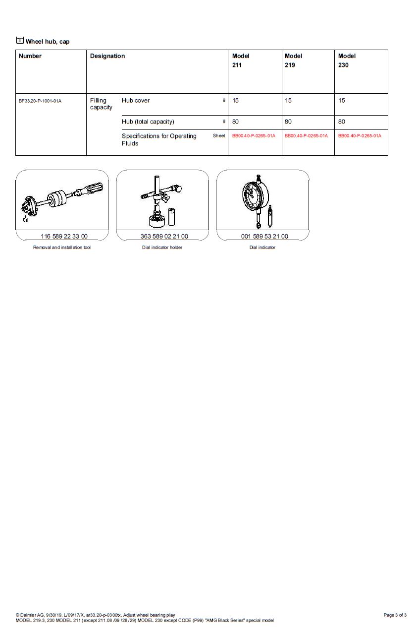
Step 4) Use a dial indicator and magnetic base and set it up as shown below. I obtained the digital gauge and magnetic base from Harbor Freight for ~$42. The digital gauge is much nicer as it's easier to read, has inches and mm readouts, and can be zero'd out when a preload is applied. Note: use the fine adjustment on the magnetic base arm to add a small amount of preload (about .02 mm or so) to the gauge and then zero it out. This way you'll get a reading if the hub bearings have any play.
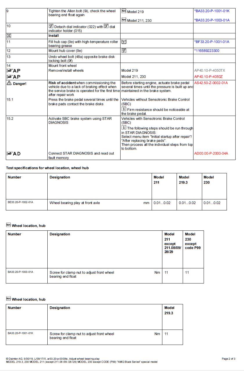
Step 5) Grab the outside of the rotor at the 12 and 6 o' clock position and attempt to push and pull the rotor parallel only to the spindle. Do not attempt to wiggle it perpendicular. As you do this, monitor the gauge and look for the readings to change. Factory spec is .01 mm - .02 mm. If you have more than this, tighten the retaining nut by hand. You shouldn't have to use any tools for this method unless you are seating new bearings in which case it's okay to use a tool to snug the nut down and then back it off to then conduct the above procedure.
Step 6) R&R is reverse as disassembly. Tighten the retaining nut bolt down, reinstall dust cap, mount wheel, lower the car and go.
In my case, I had a bit of clunking going on under the front end after some significant suspension work. I raised the front end of the car and had noticeable in and out play on both wheels when grabbing them at the 12 and 6 o' clock positions and moving the wheel. After doing the above procedure, I was able to set the correct end play and the retaining nut was turned clockwise about 1/8th of a turn from the initial setting. That said, it doesn't take much to cause issues. No more clunks and knocking sensation. Let's hope the bearings are good for another few years.
I did the turn out 1/16 of a turn thing and it ended up way more play than spec. Dial indicator is my friend now.
Exactly. The ol' "by feel" method works just fine on older vehicles but not worth taking the risk on botching it up on these cars when a new hub assembly is $300+ and you run the risk of destroying your spindle.
There's only 1 screw holding the rotor to the hub and it's on the opposite side of your magnetic base. As long as you have rust holding the hub still, all will be good.
There's only 1 screw holding the rotor to the hub and it's on the opposite side of your magnetic base. As long as you have rust holding the hub still, all will be good.
This checks bearing clearance in relation to the hub and spindle. The rotor which is attached to the hub is not part of this equation.
I think he is questioning whether there could be play between the rotor and the hub because only a single screw secures it when the wheel is off. Maybe placing the magnetic end nearer that screw would reduce the chance of that error? Very nice write up on a subject I nearly skipped, because I thought I knew how to do this. I didn't.
I think he is questioning whether there could be play between the rotor and the hub because only a single screw secures it when the wheel is off. Maybe placing the magnetic end nearer that screw would reduce the chance of that error? Very nice write up on a subject I nearly skipped, because I thought I knew how to do this. I didn't.
Ah, I see...perhaps. However, if that screw was loose, there would be no play if the wheel is still bolted to the hub. Another easy thing to check though.
2007 e63 estate, 1998 ITB golf, ITE scirocco (sold to a collector in Japan)
good but not fully correct
while this post is very good and mostly correct, i want to make sure that it is done well. the post shows a dial indicator mounted on a magnetic mount on the disk. the indicator indicates, in this case, the difference from the center of the spindle to disc. this is correct. the poster says that one should not do anything but pull parallel to the spindle at 6 and 12. this is not quite correct. parallel means nothing here. one should pull the disc in the axial direction (or, if you really like "parallel", parallel to the axis of the spindle.) the real problem, though, is that in the case of the poster, the only thing holding the disk to hub is a security bolt. that bolt is off center and, therefore, applies a torque that may result in a non parallel position of the hub face and the disc back. it is also quite small and, therefore, cannot provide much of the torque required to pull in the disc as a single fastener. mercedes says to drive in a lug bolt opposite that security bolt so that the disc is held securely against the hub face. otherwise, you are measuring the play of the bearing along with the play of the disc against the hub. your measurements will result in a too loose situation. i think my security bolt sucks so i use three lug bolts to pull on the disc to the hub. this works better. yeah, i know this seems pedantic; but, you've got a 100k$ car and want things correct, yes?
man, thanks so much for this detailed write-up. i've been experiencing clunking noises on the front axle of my S204 while steering in stationary position. in recent months i changed upper/lower control arms, drop links and sway bar mounts to no avail. earlier today was at the tire shop installing new shoes to the car and the mechanic attempted to diagnose what was going on with this, he felt some play at the front wheels and said he was sure it was the bearings. while they worked on the wheel alignment i came across this post on my phone and asked the guy to follow step by step what you had done. 15 minutes after, new wheels and a front suspension that finally feels like new.
Mercedes SLR McLaren 722 S Is Extremely Rare Example Modified by McLaren
Slideshow: A one-of-one U.S.-spec Mercedes-Benz SLR McLaren Roadster became even rarer after a factory-backed transformation at McLaren's headquarters.