


supercharge m104

Member
Joined: Mar 2005
Posts: 102
Likes: 0
i just looked back thru this post and everyone arguing in this thread all have fast mercs as it is, and are argueing for what they personally have/drive,
-no one is going to win this arguement-
give up and leave it to whipple to keep us updated about his build
-no one is going to win this arguement-
give up and leave it to whipple to keep us updated about his build
MBWorld Fanatic!
Joined: May 2005
Posts: 2,494
Likes: 17
From: REHOBOTH BEACH DE
88-300CE TWIN TURBO, 99-C43, 05-G55K, 71-280SL, 94-E320 CAB, 08 CLK63 BLACK SERIES
I agree that there is a problem with getting the power to the ground. But the rear suspension is identical to w202, w210, w129, etc., until the w211, w230, and newer big car chassis. The transmission is actually tougher than you would imagine. I never did kill my original 722.3, although it was close at 150,000 miles. I have been thinking a lot about what the drive line can handle. I think that the center u-joint is probably the weakest point. Then the half shafts.
I agree that there have been some pretty amazing claims of power on some other threads, but until I try I have no real reason to claim bs. I do know that the early m104 and the m103 have some pretty robust parts in them. The rods and crank are the same as the 3.2l m104, but the pistons on the m104 are a little less beefy. Mainly the skirts are smaller. Ring lands and such are the same. I also do not believe that any inline mercedes 6 can handle more than 7500 rpm sustained. Mainly there is no reason as they stop making any more power much lower.
I agree that there have been some pretty amazing claims of power on some other threads, but until I try I have no real reason to claim bs. I do know that the early m104 and the m103 have some pretty robust parts in them. The rods and crank are the same as the 3.2l m104, but the pistons on the m104 are a little less beefy. Mainly the skirts are smaller. Ring lands and such are the same. I also do not believe that any inline mercedes 6 can handle more than 7500 rpm sustained. Mainly there is no reason as they stop making any more power much lower.
The 722 needs a higher stall converter, and I too would question the remainder of the drive train.
High RPM is useless as these motors are designed for torque...just look at the stock specifications.
Forget about horsepower and look at the torque you can produce...probably 10%-20% more then the horsepower and down around 4000 rpm.


Thread Starter
Super Member
Joined: Oct 2008
Posts: 837
Likes: 25
From: seattle
1990 300ce supercharged and intercooled
I actually had my torque converter stalled at about 600rpm higher than stock on my old transmission. It was good for making power out of the whole but I never got a decent launch after that. The 722.6 has a higher stall already. I can power brake up to 2100 rpm before my rear brakes can not hold. I am planning on putting some drag radials on for the track this year. Maybe it will go fast or maybe it will break. I have put several solid joints in the rear suspension and the subframe is on solid mounts. The rear differential is mounted with solid mounts and the left engnine mount is solid. There is not a lot of flex in the rear end any more. This helps a lot with wheel hop. Just need a sticky track and some good tires.

Senior Member


Joined: Nov 2008
Posts: 324
Likes: 37
From: Wichita
Plays With Cars
It's pretty stupid to debate the cost efficiency of custom fabbing an FI setup or engine swaps. At the end of the day, it's almost always cheaper to sell your car and use your mod money at the dealership to upgrade to something else. Mod your car because you love it and want something unique, not because you think it's cost effective.

MBWorld Fanatic!
Joined: Feb 2004
Posts: 5,475
Likes: 5
From: City with Tall buildings!
C43/55,2k11 Volvo S60 T6AWD,2k Audi B5 S4,95 Eagle Talon Tsi AWD 500+awhp

MBWorld Fanatic!
Joined: Feb 2004
Posts: 1,559
Likes: 0
From: Portsmouth, NH
none
I actually had my torque converter stalled at about 600rpm higher than stock on my old transmission. It was good for making power out of the whole but I never got a decent launch after that. The 722.6 has a higher stall already. I can power brake up to 2100 rpm before my rear brakes can not hold. I am planning on putting some drag radials on for the track this year. Maybe it will go fast or maybe it will break. I have put several solid joints in the rear suspension and the subframe is on solid mounts. The rear differential is mounted with solid mounts and the left engnine mount is solid. There is not a lot of flex in the rear end any more. This helps a lot with wheel hop. Just need a sticky track and some good tires.
It's interesting to read about the various mounting points you've converted to solid. What did you use for material? Did you just clone the mount at hand with say aluminum or something? I've seen solid motor mounts before that were what I believe to be aluminum. This is a very curious area for me because I've found nothing in the MB community where someone has address chassis/engine torque issues. I toyed around with the idea of mounting a robust engine dampener arm to the drivers side but haven't found any structure I'm comfortable bolting it to on the motor. My luck it would shear off a head bolt if I mounted it there.
The problem is that I have brand new motor mounts and it moves alot under load. Every spring I find myself grinding and whacking new clearances in the engine bay. Would switching out the passenger side motormount with a solid piece still retain some drivability or would it shake and break things? I'm thinking that if I haulted movement on the passenger side the driver's side mount would be motionless and offer no damening or flex? Does a I-6 motor mount differently where this can be done? I feel like the M113 needs be limiteded in movement but still retain some....
..stiffening up the rest of the chassis is a future need also.
Thread Starter
Super Member
Joined: Oct 2008
Posts: 837
Likes: 25
From: seattle
1990 300ce supercharged and intercooled
What you want to do is the driver's side as it is the side that lifts. The m104 is pretty easy as it is straight through mount. I do not remember the v8 bushing for sure on a 202 but I think is has an offset angle for bolt locations. What you need to build is a two piece mount with a pivot in the middle. The pivot point will have your bushing in it. Sort of like a control arm bushing. The other solution is a torque strap around the bushing. This I have never tried building, but this was mercedes solution to the v12tt. There is a stainless steel woven strap wrapped around the engine mount. You get all the comfort and no lift. There is still side to side movement also.
I started off with the rear diff mounts with aluminum, but then I discovered delrin and uhmw. UHMW is great as it is cheap and easy to machine and as long as it is not a wear position. like a control arm bushing it is perfect. My engine mount and subframe mounts are made out of this. Any bushings for sway bars and suspension arms are made from delrin. I have to warn that the delrin bushings can be very squeaky sometimes.
I started off with the rear diff mounts with aluminum, but then I discovered delrin and uhmw. UHMW is great as it is cheap and easy to machine and as long as it is not a wear position. like a control arm bushing it is perfect. My engine mount and subframe mounts are made out of this. Any bushings for sway bars and suspension arms are made from delrin. I have to warn that the delrin bushings can be very squeaky sometimes.
MB World Stories
The Best of Mercedes & AMG

Manual Mercedes? 6 Times Sindelfingen Let Drivers Have All The Fun
Verdad Gallardo
Mercedes SLR McLaren 722 S Is Extremely Rare Example Modified by McLaren
Verdad Gallardo
8 Classic Boxy Mercedes Designs That Have Aged Like Fine Wine
Verdad Gallardo
Flawlessly Restored Mercedes 190E Evo II Heads to Auction
Verdad Gallardo
Electric Mercedes C-Class Unveiled: 11 Things You Need to Know
Verdad Gallardo
Mercedes EQS Gets A Major Update: Everything You Need to Know
Verdad Gallardo
5 Underrated Mercedes-Benz Models That Don't Get the Love They Deserve
Verdad Gallardo
Mercedes 300D Has Pushed Well Past 1 Million Miles and It Ain't Stopping
Verdad Gallardo
10 Most Reliable Mercedes-Benz Models You Can Buy Used
Verdad GallardoMBWorld Fanatic!
Joined: May 2005
Posts: 2,494
Likes: 17
From: REHOBOTH BEACH DE
88-300CE TWIN TURBO, 99-C43, 05-G55K, 71-280SL, 94-E320 CAB, 08 CLK63 BLACK SERIES
A back on topic question!!
It's interesting to read about the various mounting points you've converted to solid. What did you use for material? Did you just clone the mount at hand with say aluminum or something? I've seen solid motor mounts before that were what I believe to be aluminum. This is a very curious area for me because I've found nothing in the MB community where someone has address chassis/engine torque issues. I toyed around with the idea of mounting a robust engine dampener arm to the drivers side but haven't found any structure I'm comfortable bolting it to on the motor. My luck it would shear off a head bolt if I mounted it there.
The problem is that I have brand new motor mounts and it moves alot under load. Every spring I find myself grinding and whacking new clearances in the engine bay. Would switching out the passenger side motormount with a solid piece still retain some drivability or would it shake and break things? I'm thinking that if I haulted movement on the passenger side the driver's side mount would be motionless and offer no damening or flex? Does a I-6 motor mount differently where this can be done? I feel like the M113 needs be limiteded in movement but still retain some....
..stiffening up the rest of the chassis is a future need also.
This will limit the chassis flexing.
As far as the motor what I used on factory race hemis was a strap from the frame to the engine which would prevent the engine from trying to turn sideways under torque.
You could fabricate as a solid bracket or use a stainless steel aircraft cable.
Very effective method of keeping the engine straight

Last edited by RBYCC; Jan 7, 2009 at 11:26 AM.
MBWorld Fanatic!
Joined: May 2005
Posts: 2,494
Likes: 17
From: REHOBOTH BEACH DE
88-300CE TWIN TURBO, 99-C43, 05-G55K, 71-280SL, 94-E320 CAB, 08 CLK63 BLACK SERIES
The eyelet is then bolted to the chassis and the other end to the engine block.
If the cable has enough length you could include a turnbuckle to pull the cable tight after it is bolted.
MBWorld Fanatic!
Joined: Feb 2004
Posts: 1,559
Likes: 0
From: Portsmouth, NH
none
I found info like this on the web used mostly on older domestics and big motor cars. Many called it a torque strap, mostly solid turnbuckles and a couple using actual chain. This idea sounds like it would be best in terms of simplicity and being effective. I'm sure custom material mounts would cost me a great deal. I'll be working on some designs and materials once I can get under there again. I'm trying to recall what I saw for mounting points when I replaced the mounts. I'm thinking a stainless cable of some sort and maybe having an extension piece fabricated so I can mount the eyelet off of the OEM motor mount point, maybe.
..would the trans mount have a large effect on keeping the motor still? Mine is the original mount.
I'm sure custom material mounts would cost me a great deal. I'll be working on some designs and materials once I can get under there again. I'm trying to recall what I saw for mounting points when I replaced the mounts. I'm thinking a stainless cable of some sort and maybe having an extension piece fabricated so I can mount the eyelet off of the OEM motor mount point, maybe...would the trans mount have a large effect on keeping the motor still? Mine is the original mount.
MBWorld Fanatic!

Joined: Oct 2005
Posts: 1,083
Likes: 11
From: PNW
2001 E430
Thread Starter
Super Member
Joined: Oct 2008
Posts: 837
Likes: 25
From: seattle
1990 300ce supercharged and intercooled
The v12 mount may fit the c class? I would go to the dealer and compare the two. The torque strap works for holding power down so you do not rip your engine mount in half, but a more solid mount keeps it from moving around better. Another thing I have seen is on old mounts people have filled them with urethane after drilling a hole in them and draining them. Eventually the rubber breaks down and they have to be repl. anyway. My mount is pretty simple with a uhmw mount and I added a rubber control arm bushing to it to soften the engine vibrations. I think I will add another to the other end someday to soften it a little more.
The way to make the bushing for the c class though is really not hard. There will just be two pieces. A top piece that bolts to the engine arm. And a lower that bolts to the chassis. Then a bushing with a bolt through it that mounts the two. You could really just use a lower control arm bushing set.
I could make something like this if anyone is interested.
I should be able to do it for less than $200. Maybe less, I do not know how long it would take to make the first one.
MBWorld Fanatic!
Joined: Feb 2004
Posts: 1,559
Likes: 0
From: Portsmouth, NH
none
Don't laugh at my MSpaint work!
Is this what you kinda mean using a bolt with bushings? Roughly...
[IMG]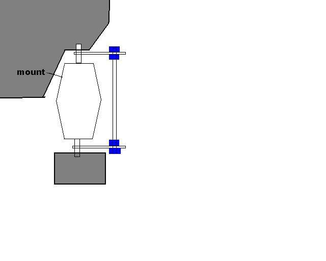 [/IMG]
The V12TT mount sounds like a great design, I'll check on fitment but have a feeling it wouldn't.
Is this what you kinda mean using a bolt with bushings? Roughly...
[IMG]
[/IMG]The V12TT mount sounds like a great design, I'll check on fitment but have a feeling it wouldn't.
MBWorld Fanatic!
Joined: Oct 2005
Posts: 1,083
Likes: 11
From: PNW
2001 E430
 In all seriousness you're right the guy does seem like a big douche but he's probably going to be around for many years to come.
Just this once out of respect for your badass C43 I'll go sig free

MBWorld Fanatic!
Joined: Feb 2004
Posts: 1,559
Likes: 0
From: Portsmouth, NH
none
C'mon now....This is Vince the "Slap Chop" bit*h. And you thought he was a one trick pony. I can see why you would be jealous of his stylish microphone and his awesome lines like "you're gonna love my nuts" In all seriousness you're right the guy does seem like a big douche but he's probably going to be around for many years to come.
Just this once out of respect for your badass C43 I'll go sig free
In all seriousness you're right the guy does seem like a big douche but he's probably going to be around for many years to come.Just this once out of respect for your badass C43 I'll go sig free
")
He's the future "Billy Mays" that was pushing oxyclean, mighty putty, weed devil thing, insurance, you name it...LOL...and lastly, each of them could buy me and sell me for less than they bought $me$ for. So jokes on me I guess!LOL
MBWorld Fanatic!
Joined: Feb 2004
Posts: 1,559
Likes: 0
From: Portsmouth, NH
none
MBWorld Fanatic!
Joined: May 2005
Posts: 2,494
Likes: 17
From: REHOBOTH BEACH DE
88-300CE TWIN TURBO, 99-C43, 05-G55K, 71-280SL, 94-E320 CAB, 08 CLK63 BLACK SERIES
I found info like this on the web used mostly on older domestics and big motor cars. Many called it a torque strap, mostly solid turnbuckles and a couple using actual chain. This idea sounds like it would be best in terms of simplicity and being effective. I'm sure custom material mounts would cost me a great deal. I'll be working on some designs and materials once I can get under there again. I'm trying to recall what I saw for mounting points when I replaced the mounts. I'm thinking a stainless cable of some sort and maybe having an extension piece fabricated so I can mount the eyelet off of the OEM motor mount point, maybe.
..would the trans mount have a large effect on keeping the motor still? Mine is the original mount.
I'm sure custom material mounts would cost me a great deal. I'll be working on some designs and materials once I can get under there again. I'm trying to recall what I saw for mounting points when I replaced the mounts. I'm thinking a stainless cable of some sort and maybe having an extension piece fabricated so I can mount the eyelet off of the OEM motor mount point, maybe...would the trans mount have a large effect on keeping the motor still? Mine is the original mount.
I would lean away from making the motor mounts rigid to limit the motor movement under torque as you could in time strain and stretch the motor mount bolts.
Much more labor to change/modify mounts compared to a simple bolt on strap/wire.
I first used the SS wire assembly successfully in a very high torque motor almost forty years ago !.
A strut to connect the shock towers as I previously mentioned will limit the torque applied to the front chassis rails.
What's being discussed now in this thread is very important...
You need to control the power you're making and get it to the road without breaking stuff..
Something that many forget when looking for big power gains !

Thread Starter
Super Member
Joined: Oct 2008
Posts: 837
Likes: 25
From: seattle
1990 300ce supercharged and intercooled
I agree that to rigid can be a problem. But what I am talking about is more along the lines of a normal solid rubber mount like a Chevy. You have to admit that mercedes mounts are extremely flexible. The torque strap is definitely a good way to go. But there is still a ton of lateral play in the mounts. I really wanted the engine not to shift right and left either.
So here we go again. The mount is basically a hinge point like a lower control arm bushing. Instead of hooking the lower control arm, there is a bolt on each piece of the hinge. The bushing is pressed in to the sleeve and provides dampening. The reason for the hinge is to provide the angle between the two bolting points. You cannot use one straight through bolt.
So here we go again. The mount is basically a hinge point like a lower control arm bushing. Instead of hooking the lower control arm, there is a bolt on each piece of the hinge. The bushing is pressed in to the sleeve and provides dampening. The reason for the hinge is to provide the angle between the two bolting points. You cannot use one straight through bolt.
MBWorld Fanatic!
Joined: May 2005
Posts: 2,494
Likes: 17
From: REHOBOTH BEACH DE
88-300CE TWIN TURBO, 99-C43, 05-G55K, 71-280SL, 94-E320 CAB, 08 CLK63 BLACK SERIES
I agree that to rigid can be a problem. But what I am talking about is more along the lines of a normal solid rubber mount like a Chevy. You have to admit that mercedes mounts are extremely flexible. The torque strap is definitely a good way to go. But there is still a ton of lateral play in the mounts. I really wanted the engine not to shift right and left either.
So here we go again. The mount is basically a hinge point like a lower control arm bushing. Instead of hooking the lower control arm, there is a bolt on each piece of the hinge. The bushing is pressed in to the sleeve and provides dampening. The reason for the hinge is to provide the angle between the two bolting points. You cannot use one straight through bolt.
So here we go again. The mount is basically a hinge point like a lower control arm bushing. Instead of hooking the lower control arm, there is a bolt on each piece of the hinge. The bushing is pressed in to the sleeve and provides dampening. The reason for the hinge is to provide the angle between the two bolting points. You cannot use one straight through bolt.
The Merc mounts are basically almost liquid filled and not what I would call a solid biscuit mount like a Chevy.
Should work...keep us posted !
MBWorld Fanatic!
Joined: Feb 2004
Posts: 1,559
Likes: 0
From: Portsmouth, NH
none
I was told they were, at least for the V8's. I remember someone saying it was a fluid for dampening virbrations. Makes sense I guess. I would love a stainless weave around it like the V12 mounts noted above.


