When you click on links to various merchants on this site and make a purchase, this can result in this site earning a commission. Affiliate programs and affiliations include, but are not limited to, the eBay Partner Network.
Engine M137 - retaining device designed for position.ing the camshaft
Hello, I have a question if any of you 'produced' your own camshaft locks for the M137 engine.
The design is not complicated and the prices of such a set are a bit exaggerated.
I am looking for dimensions, maybe some of you have such data and could provide it.
regards
Master material. Thank you very much for sharing it.
I have one support question ..
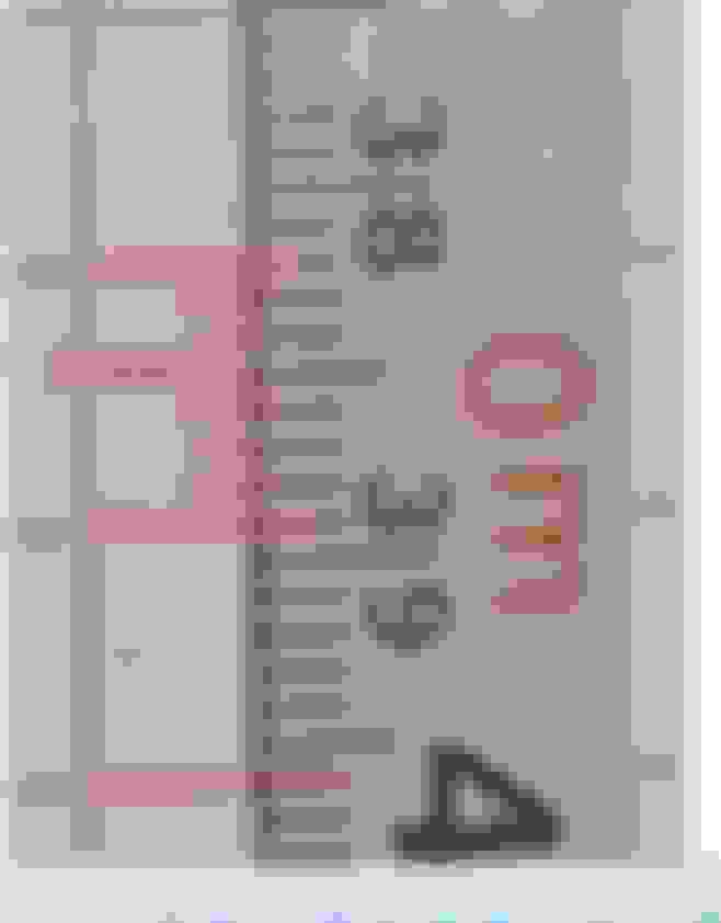
I see you are from the Netherlands so the ruler in the photo is probably in the metric system. Unless it's some kind of specialist tool.
Can I assume that, according to what can be read from the ruler, one square is 7 millimeters ?
I am asking because in the description there is information about the dimensions of 10 mm by 10 mm.
Thank you again for sharing these materials - best regards - great material
Master material. Thank you very much for sharing it.
I have one support question ..
I see you are from the Netherlands so the ruler in the photo is probably in the metric system. Unless it's some kind of specialist tool.
Can I assume that, according to what can be read from the ruler, one square is 7 millimeters ?
I am asking because in the description there is information about the dimensions of 10 mm by 10 mm.
Thank you again for sharing these materials - best regards - great material
Gosh, I missed that one. You seem to be correct. The squares should be 7x7mm instead of 10x10. I'll change the upload.
Are you going to create 3D models based on the images?
I would like to make such a blockage.
I have access to any available CAD software and to many machines. I work in a large production company and making such "clamp" if I had documentation is not a challenge.
The prices of this tool are a bit absurd - at least in Poland.
A little better quality - at least it seems from the photo - is the minimum cos 104 euro.
As you know, the best fun is to do it yourself, so I'll try.
If it succeeds ...
All the drawings will be available, maybe someone will also want to play.
The topic is a bit stuck and I'm looking for an idea.
I put all the photos into Auto Cad and unfortunately, after changing the perspective of the photos, the dimensions `` run away '' ...
While the outer dimensions can be determined, the cuts for the camshafts are a problem.
A heavy subject to accurately reproduce the element.
I am not a professional mechanic.
I'd rather save myself and everyone the trouble of replacing the chain.
That's why I care about the dimensions.
Buying a timing blockade is an expensive business.
It's a pity a little money for a element I will use only once.
For this price, I would rather buy new timing components.
Thank you very much for the photos but so far I have no idea how to move forward.
I do not know if it will be clearly visible but here is an example of what happens after changing the perspective of the photo, the grids move too much.
Mercedes SLR McLaren 722 S Is Extremely Rare Example Modified by McLaren
Slideshow: A one-of-one U.S.-spec Mercedes-Benz SLR McLaren Roadster became even rarer after a factory-backed transformation at McLaren's headquarters.