When you click on links to various merchants on this site and make a purchase, this can result in this site earning a commission. Affiliate programs and affiliations include, but are not limited to, the eBay Partner Network.
I repaired my failed shifter module in our W211 E500 wagon. I found two cracked solder joints on an SMD sensor inside the module. This internal cracked solder issue may affect other similar MB shifter modules or may have be unique to my shifter module. The repair is a bit technical but not out the realm of ability for someone with some hand tools and a soldering iron.
I had to remove the shifter module/ assembly from the car and then disassemble it to do so. This requires partial removal of the console to get at the shifter module.
Codes displayed on diagnosis equipment will be P1856 and P240C. Symptoms include but may not be limited to inability to move the selector from Park or from Neutral to Park, car only runs in 1st gear, not being able to remove the key due to inability to move the gear selector into park, not being able to start the car due to the computer not knowing what gear the vehicle is in and/or no gear position shown in the digital dash display.
After the shifter module is removed from the vehicle it will need to be disassembled for access to a black electronic switch/ sensor module that is bolted onto the side of the main shift lever pivot frame. The shift lever will need to be moved as required to allow the black electronic switch/ sensor module to be released from the main shift lever pivot frame as there are pins on the shift lever shaft that need to be clocked at 9 & 3 o'clock so the black electronic switch/ sensor module will slide off the shift lever shaft. The shift lever can be unlocked and moved simply by pushing on the solenoid "button" that faces rearward on the shifter module frame. Disconnect any remaining wire connectors and remove the two torx screws that hold the black electronic switch/ sensor module. The black electronic switch/ sensor module will slide off the shift lever shaft.
Next remove (4) tiny torx screws that hold the cover on one side of the black electronic switch/ sensor module. I did not have any tiny torx wrenches so I used Allen keys and small jeweler screwdrivers. NOTE:Keep an eye on how the cover comes apart so you will understand how to put it back together keeping the internal pivoting center piece aligned with a white plastic slider switch catch that is located on the other side of the black electronic switch/ sensor module.
Now get out a good high powered Lupe or magnifying glass and inspect the (4) U-shaped black plastic devices soldered to the PC board. These devices are actually photo-optic light sensors that the internal pivoting center piece slides through. That is why there are these light blocking fences on that internal pivoting center piece I my case there were two cracked solder joints on one of these U-shaped black plastic photo-optic light sensors. I simply used a low power 15 watt soldering iron to re-solder these two cracked solder joints, re-assembled everything and the problem with the failed transmission shifter module was solved.
Wow Good spotting.
Around the early 2000 MB(and others) started specking eco friendly solder, it has all kids of issues that were unheard of before.
Just saw same solder fail on son's 2006 Jetta.
I repaired my failed shifter module in our W211 E500 wagon. I found two cracked solder joints on an SMD sensor inside the module. This internal cracked solder issue may affect other similar MB shifter modules or may have be unique to my shifter module. The repair is a bit technical but not out the realm of ability for someone with some hand tools and a soldering iron.
I had to remove the shifter module/ assembly from the car and then disassemble it to do so. This requires partial removal of the console to get at the shifter module.
Codes displayed on diagnosis equipment will be P1856 and P240C. Symptoms include but may not be limited to inability to move the selector from Park or from Neutral to Park, car only runs in 1st gear, not being able to remove the key due to inability to move the gear selector into park, not being able to start the car due to the computer not knowing what gear the vehicle is in and/or no gear position shown in the digital dash display.
After the shifter module is removed from the vehicle it will need to be disassembled for access to a black electronic switch/ sensor module that is bolted onto the side of the main shift lever pivot frame. The shift lever will need to be moved as required to allow the black electronic switch/ sensor module to be released from the main shift lever pivot frame as there are pins on the shift lever shaft that need to be clocked at 9 & 3 o'clock so the black electronic switch/ sensor module will slide off the shift lever shaft. The shift lever can be unlocked and moved simply by pushing on the solenoid "button" that faces rearward on the shifter module frame. Disconnect any remaining wire connectors and remove the two torx screws that hold the black electronic switch/ sensor module. The black electronic switch/ sensor module will slide off the shift lever shaft.
Next remove (4) tiny torx screws that hold the cover on one side of the black electronic switch/ sensor module. I did not have any tiny torx wrenches so I used Allen keys and small jeweler screwdrivers. NOTE:Keep an eye on how the cover comes apart so you will understand how to put it back together keeping the internal pivoting center piece aligned with a white plastic slider switch catch that is located on the other side of the black electronic switch/ sensor module.
Now get out a good high powered Lupe or magnifying glass and inspect the (4) U-shaped black plastic devices soldered to the PC board. These devices are actually photo-optic light sensors that the internal pivoting center piece slides through. That is why there are these light blocking fences on that internal pivoting center piece I my case there were two cracked solder joints on one of these U-shaped black plastic photo-optic light sensors. I simply used a low power 15 watt soldering iron to re-solder these two cracked solder joints, re-assembled everything and the problem with the failed transmission shifter module was solved.
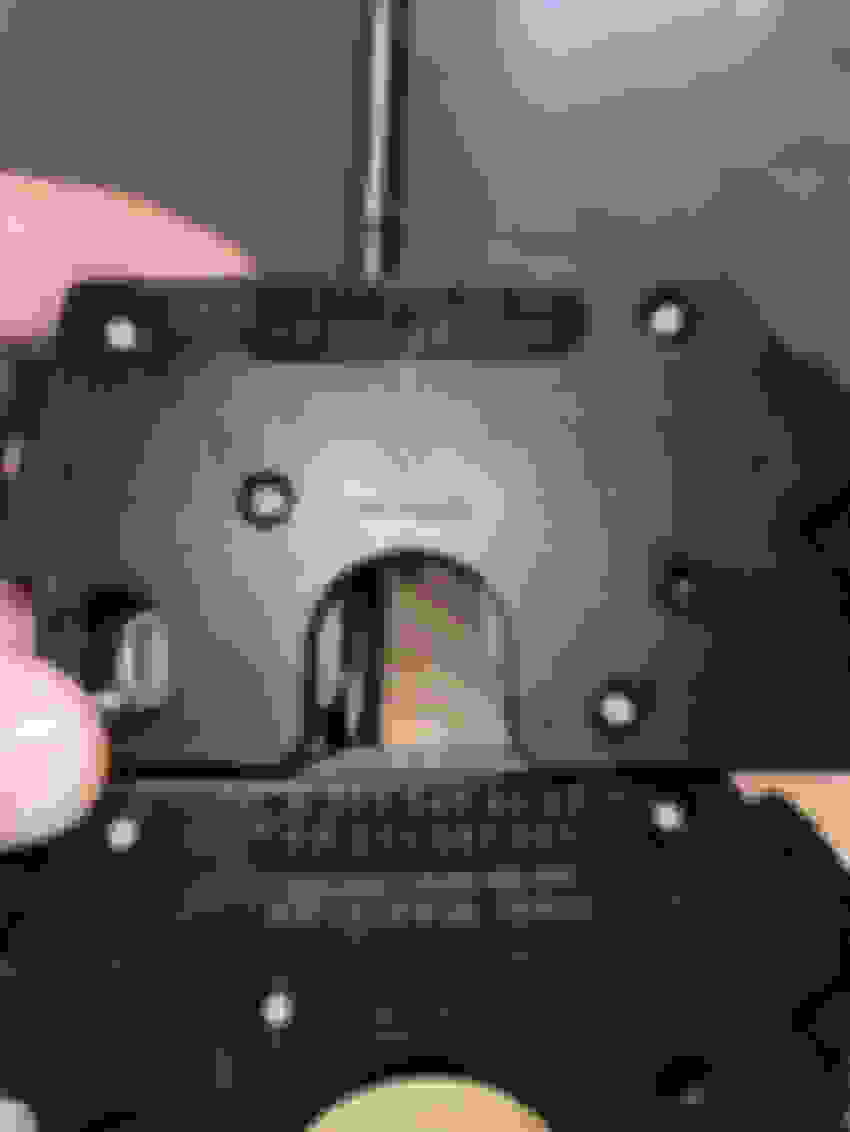
May I ask if you floor shifter is put together by screws or by glue? Mine is glued firmly together and I am wondering how I can take them apart...
glued at the red arrow pointed areas another 2 on the other side
OP, congratulations on fixing TCPT1200 soldering issue. My 2005 W220 S500 4Matic has the same P1856 issue. I opened up the shifter module. My optical gates (TCPT1200) seems to be ok. I do not see any cracked soldering. I thought of putting extra solder dabs on the existing ones. I could do so only for the outside points. Inside points are so narrow I afraid if I solder I may short them. I am thinking of using Silver paintable conductor (which comes in a syringe) sells on ebay. I have ordered and waiting.
If this method does not solve, I may have to go for replacement part. Fingers crossed.
I recently posted this thread with video of the shifter not wanting to shift past neutral into park. Sometimes the behavior is reversed and it doesn’t want to shift out of park and into reverse. You’ll see in the video that as soon as I turn the car off, it will shift into park. I was immediately suspicious of an electrical/sensor issue vs mechanical.
But as the responses to my post come in, from knowldgeable forum contributors, they continue to point to a $2,500 repair for a possible defective weld. It’s maddeningly MB at it’s worse!
regretfuly, it must be cut by inserting a sharp knife or something similar. Anyway it can be put together again or simply be held by the three big nuts that hold the selctor case in place.
I repaired my failed shifter module in our W211 E500 wagon. I found two cracked solder joints on an SMD sensor inside the module. This internal cracked solder issue may affect other similar MB shifter modules or may have be unique to my shifter module. The repair is a bit technical but not out the realm of ability for someone with some hand tools and a soldering iron.
I had to remove the shifter module/ assembly from the car and then disassemble it to do so. This requires partial removal of the console to get at the shifter module.
Codes displayed on diagnosis equipment will be P1856 and P240C. Symptoms include but may not be limited to inability to move the selector from Park or from Neutral to Park, car only runs in 1st gear, not being able to remove the key due to inability to move the gear selector into park, not being able to start the car due to the computer not knowing what gear the vehicle is in and/or no gear position shown in the digital dash display.
After the shifter module is removed from the vehicle it will need to be disassembled for access to a black electronic switch/ sensor module that is bolted onto the side of the main shift lever pivot frame. The shift lever will need to be moved as required to allow the black electronic switch/ sensor module to be released from the main shift lever pivot frame as there are pins on the shift lever shaft that need to be clocked at 9 & 3 o'clock so the black electronic switch/ sensor module will slide off the shift lever shaft. The shift lever can be unlocked and moved simply by pushing on the solenoid "button" that faces rearward on the shifter module frame. Disconnect any remaining wire connectors and remove the two torx screws that hold the black electronic switch/ sensor module. The black electronic switch/ sensor module will slide off the shift lever shaft.
Next remove (4) tiny torx screws that hold the cover on one side of the black electronic switch/ sensor module. I did not have any tiny torx wrenches so I used Allen keys and small jeweler screwdrivers. NOTE:Keep an eye on how the cover comes apart so you will understand how to put it back together keeping the internal pivoting center piece aligned with a white plastic slider switch catch that is located on the other side of the black electronic switch/ sensor module.
Now get out a good high powered Lupe or magnifying glass and inspect the (4) U-shaped black plastic devices soldered to the PC board. These devices are actually photo-optic light sensors that the internal pivoting center piece slides through. That is why there are these light blocking fences on that internal pivoting center piece I my case there were two cracked solder joints on one of these U-shaped black plastic photo-optic light sensors. I simply used a low power 15 watt soldering iron to re-solder these two cracked solder joints, re-assembled everything and the problem with the failed transmission shifter module was solved.
Repair lasted a few years & now the gear shifter stopped working again (P1856) Lever Position Detection Has Failed. I pulled it and inspected the PC Board again with no obvious cracked/cold solder joints visible. There is a guy on Utube that says put the PC board in the oven at 390F for 8 minutes to let the solder flow again, but you have to be totally sure as to not disturb any of the heat loosened devices when handling it until cooled. Haven't tried that yet but I was looking at used gear selectors on the bay.
The shifter selector box in our '04 E500 wagon is a A2112672924. None used state side at the moment. It has the wires for Keyless Go up the shaft but the vehicle doesn't have that option. That has me thinking its been replaced or that's what MB had on the parts shelf that day. That being said, it appears that there are many similar selector boxes with similar numbers in the last group of four. Some with & without the Keyless Go shaft option.
Any idea what shifter selector boxes will cross with my gear shifter box without needing coding and is a drop in part for the 2004 E500 4-Matic Wagon w/o Keyless Go?
Here are some choices? A211267(1524), 1624, 2224, 4624, 4824, 6224 Thanks!
I ordered up a used 2112674824 shifter unit w/o keyless-go. It has the screwed on top (earlier) not the glued on top (later) so I figured it was from a similar vintage. We'll see if it works.
Update: I think the W211 shifter I got from the bay came from a CLS and had a different shifter arm mounted to it so it rubbed on the driveshaft No biggie as I was able to easily disassemble it and just swap the new electronic module into the old shifter.
The original unit on our '04 E500 4-Matic wagon had an arm with a slight offset to clear the drive shaft. The newer one had no offset. So in our case the original (or not so original) A2112672924 shifter internal electronic module worked with a A2112676224 internal electronic module swapped in. Both are keyless-go shifter units but the vehicle doesn't have that option. Hope this maybe helps others if their unit malfunctions. No dealer coding was required.
These electronic modules are apparently interchangeable:
Here the offset in the arm is noticeable. It wasn't so in the ad. I picked a used one that had 4 screws holding the white plastic cover on. That made it easier to swap the electronic modules. The shifters without the screws are glued together and can be pried apart I'm told. You might be able to screw them back together if you have that type anyway.
Here you can see the silver screws holding the white cover on. The glued on types look like they have the screw holes present.
Thanks to this forum I was able to fix my shifter about 2 years ago. Same cracked solder issue. I believe that the cracked solder was caused by the edge of the photogate curtain catching on the photogate itself. There were signs of scratching on mine. Lead free solder is brittle but In my opinion was not at fault. Solution is to round the corners of the curtain a bit. See photo. My SLK is my everyday car. So far no issues for almost years.
Repair lasted a few years & now the gear shifter stopped working again (P1856) Lever Position Detection Has Failed. I pulled it and inspected the PC Board again with no obvious cracked/cold solder joints visible. There is a guy on Utube that says put the PC board in the oven at 390F for 8 minutes to let the solder flow again, but you have to be totally sure as to not disturb any of the heat loosened devices when handling it until cooled. Haven't tried that yet but I was looking at used gear selectors on the bay.
The shifter selector box in our '04 E500 wagon is a A2112672924. None used state side at the moment. It has the wires for Keyless Go up the shaft but the vehicle doesn't have that option. That has me thinking its been replaced or that's what MB had on the parts shelf that day. That being said, it appears that there are many similar selector boxes with similar numbers in the last group of four. Some with & without the Keyless Go shaft option.
Any idea what shifter selector boxes will cross with my gear shifter box without needing coding and is a drop in part for the 2004 E500 4-Matic Wagon w/o Keyless Go?
Here are some choices? A211267(1524), 1624, 2224, 4624, 4824, 6224 Thanks!
Giving the reflow suggestion a shot right now (thanks for mentioning it) - the board looks good and no scratching so it's basically a last-shot-effort.
Giving the reflow suggestion a shot right now (thanks for mentioning it) - the board looks good and no scratching so it's basically a last-shot-effort.
I had to wiggle the components in mine to make the crack show. I also used a magnifying glass. Check also if your capacitors are not leaky or swollen. I am confident these are the only problems with these
boards. Good luck!
We're working on the same issue right too.. Please update when you have it back together and whether or not that resolves the issue.
P240C - CAN Signal Selector Lever Position N15/5 Is Not Plausible - Stored and current
P1865 - Shift Lever Position Identification Failure - Stored and current
2006 W220 S500
Sure no problem - it's in operation currently and there are no problems as of yet - just waiting for next weekend before I button the console back up so just wanted to be clear here, in case it seemed like I haven't actually got to test it yet (so far it's working fantastic).
We're working on the same issue right too.. Please update when you have it back together and whether or not that resolves the issue.
P240C - CAN Signal Selector Lever Position N15/5 Is Not Plausible - Stored and current
P1865 - Shift Lever Position Identification Failure - Stored and current
2006 W220 S500
We re-flowed the optical sensor solder joints (the common offenders) and success!
We can shift into R, N, D and P again with no issues/hang ups and the dash now shows what gear and mode the shifter is in.
The codes are no longer present, limp mode is no longer present and things are working!
A huge thank you to all who came before and gave us this documentation for DIY ! ! ! !
Sincerely,
Innova801
Last edited by Innova801; Sep 13, 2024 at 12:33 AM.
Reason: words
Mercedes SLR McLaren 722 S Is Extremely Rare Example Modified by McLaren
Slideshow: A one-of-one U.S.-spec Mercedes-Benz SLR McLaren Roadster became even rarer after a factory-backed transformation at McLaren's headquarters.


 No biggie as I was able to easily disassemble it and just swap the new electronic module into the old shifter.