When you click on links to various merchants on this site and make a purchase, this can result in this site earning a commission. Affiliate programs and affiliations include, but are not limited to, the eBay Partner Network.
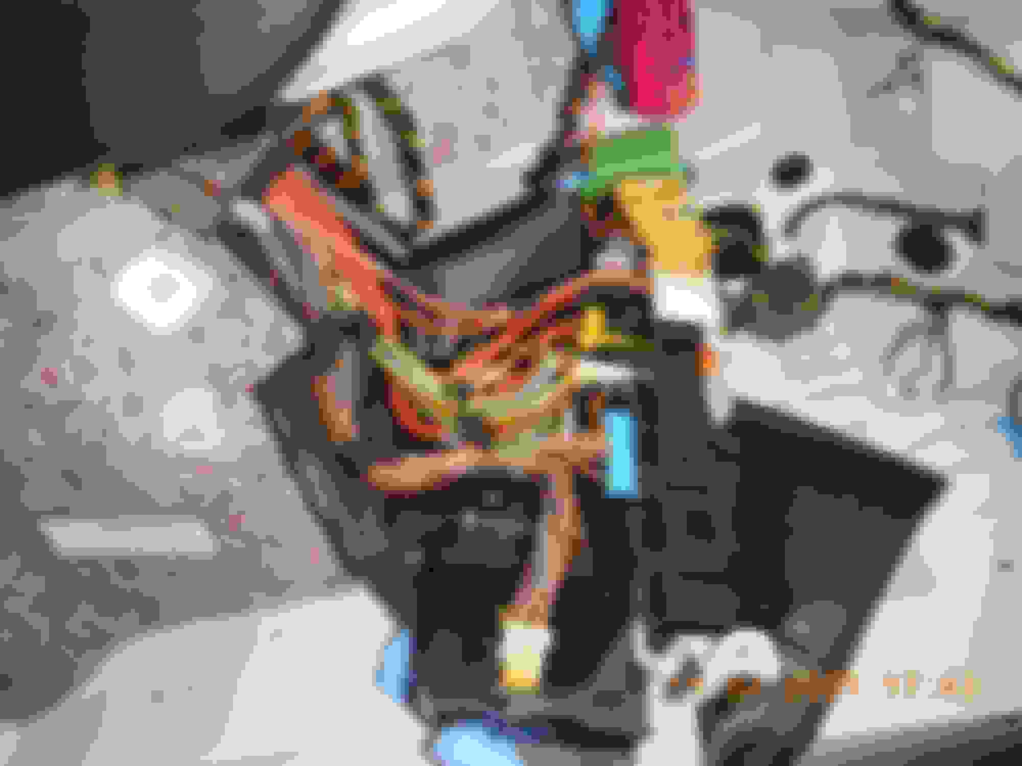
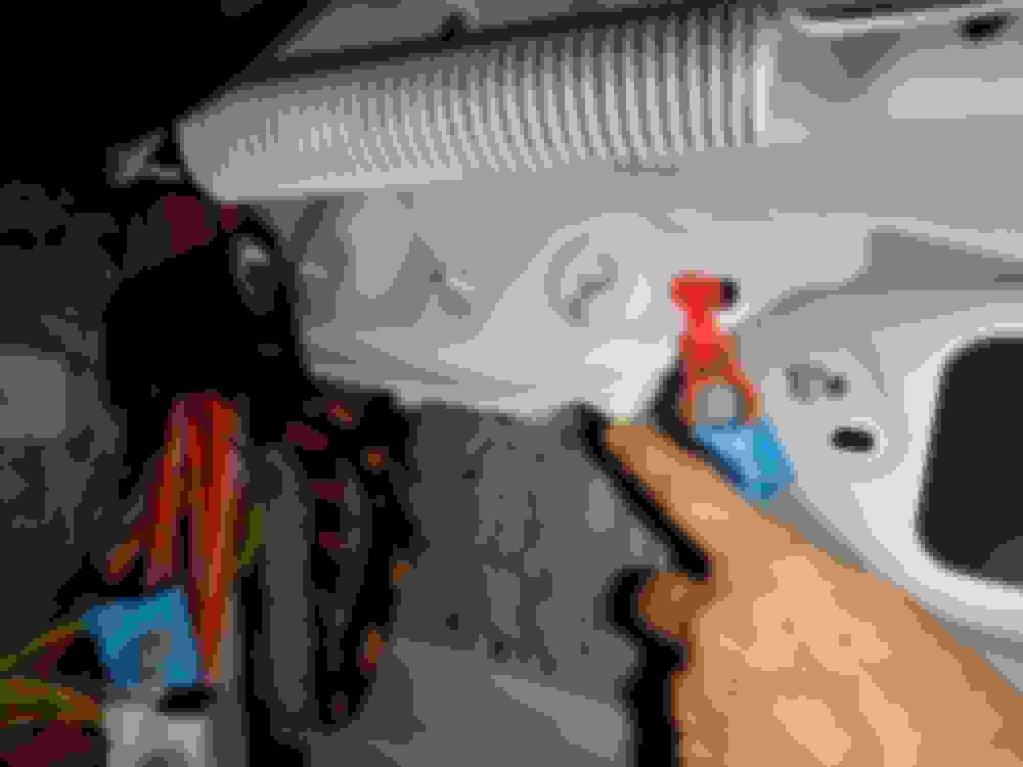
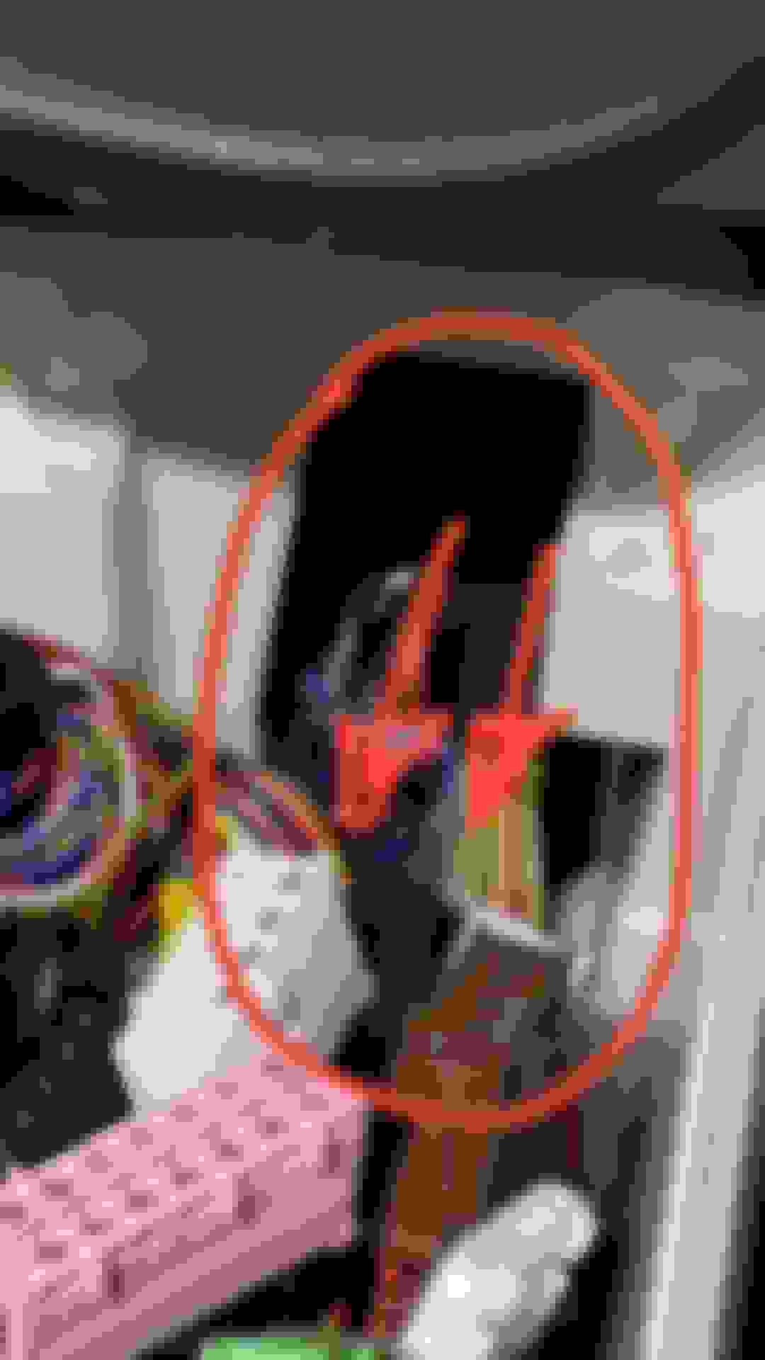
we can not lift it straight up, try to rotate and pull forward at 45� angle...
the 2 cut side corners may help extraction... slide up the whole harness rubbers
the official procedure may have extra tips to make the extraction easier
Last edited by CaliBenzDriver; 06-27-2021 at 11:42 PM.
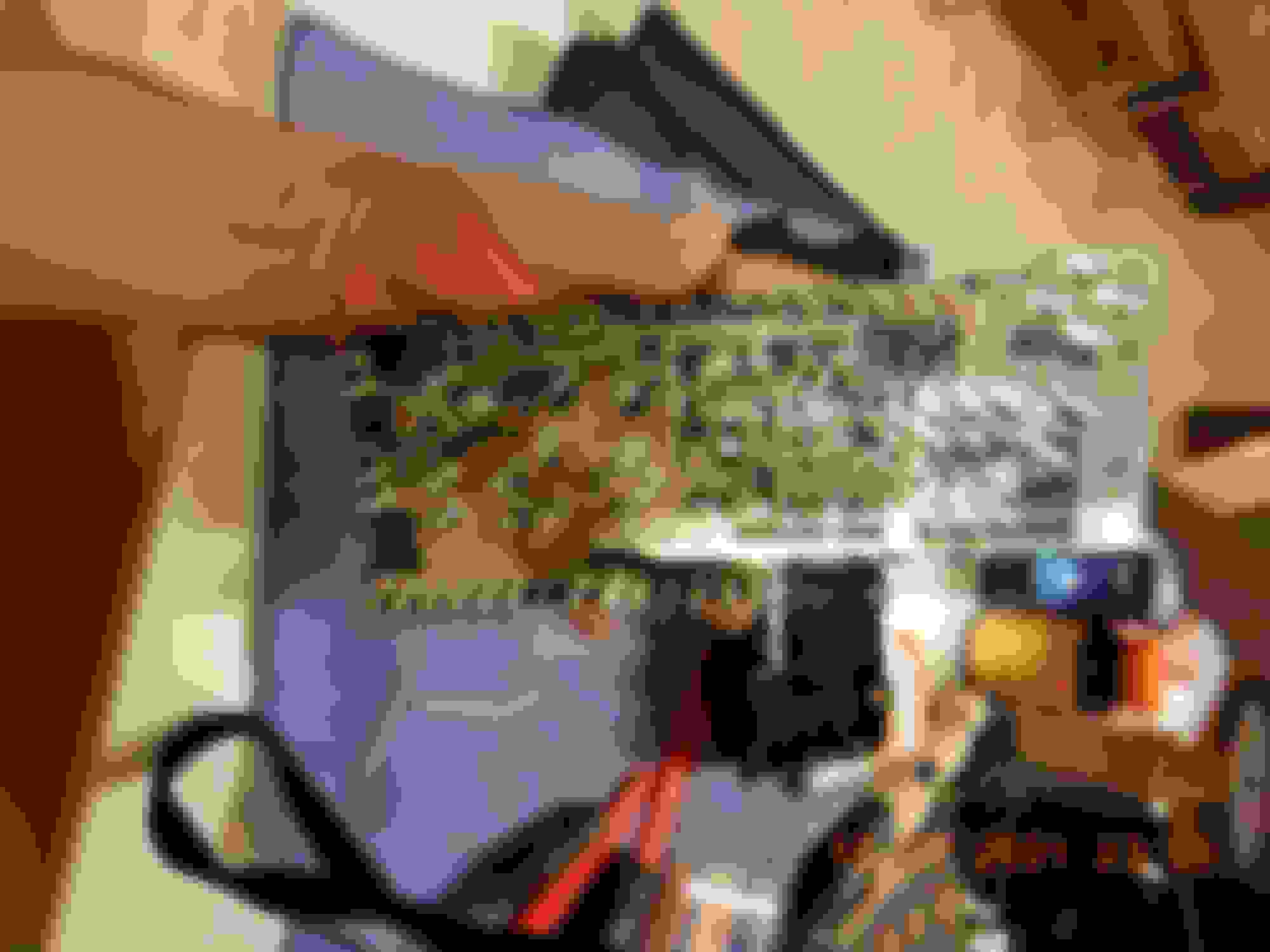
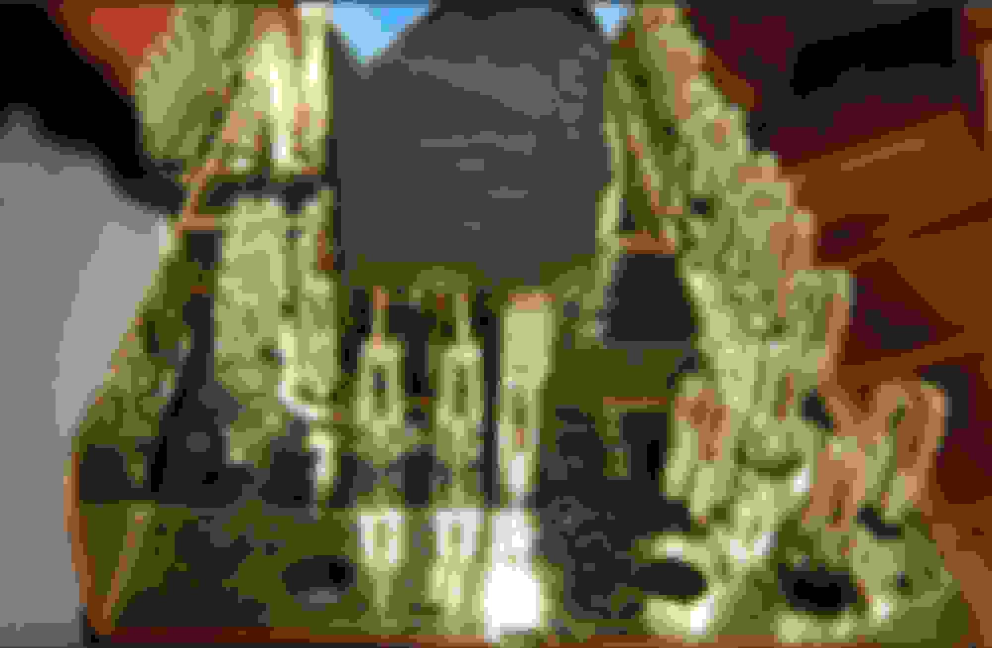
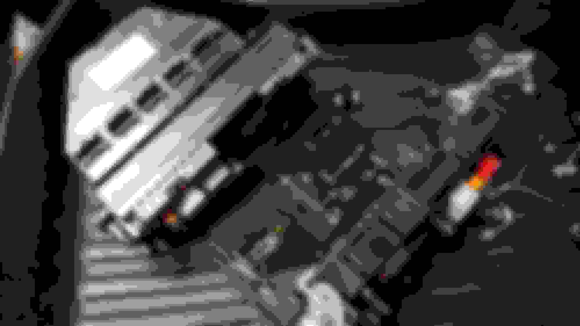
Both Front and Rear-SAM usually chat a lot over the network so I thought they should meet... I facilitated a lit'le holiday get together for them 😄
SAM's all dressed up Stripped SAM's on my bench
I invited my big 100W solder iron and silicone PCB protectant to the party so they'd go back to work in top shape.
MAKE UP STATION:
Ever board that I've seen is sadly missing a standard conformal coating. The purpose is to weatherize the circuit to prevent cross-trace oxidation after a few years.
This is what's causing stationary battery drain, ghost lights turning on by themselves, turn signal not working... that list goes on and on!
side by side specs...
high temp silicone a must of ECU available conformal coatings
COATING TIME:
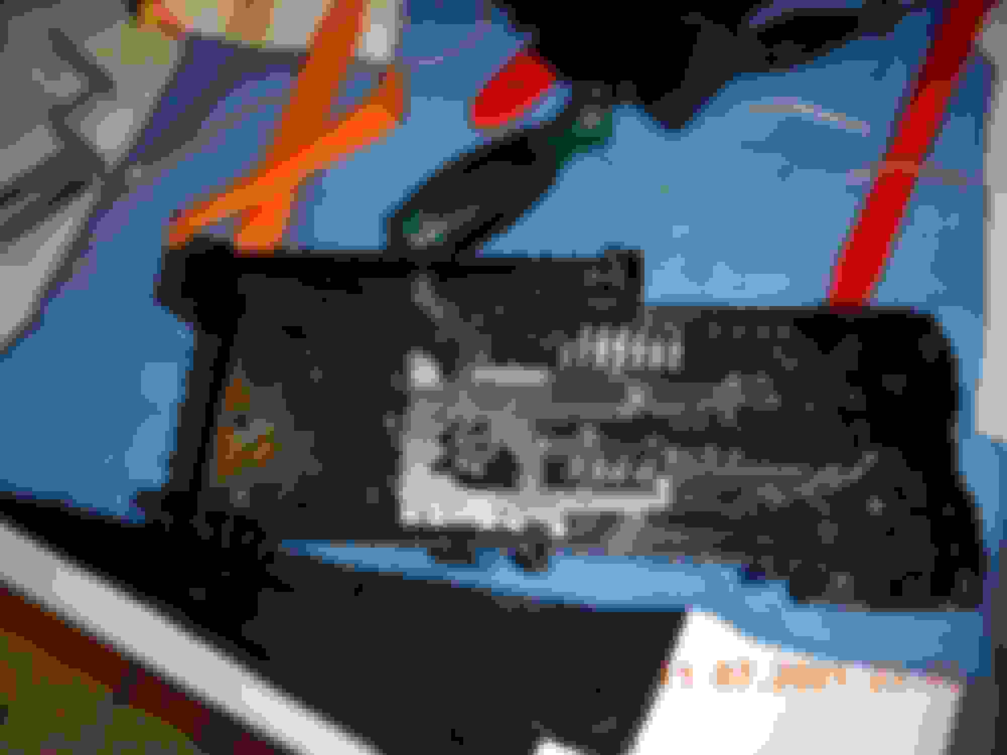
Every PCB that's going to land on my hardware bench will get a coat of high temp silicone protectant. shiny F-SAM protected on the traces side only shiny R-SAM coated on single side
THE MEAT SECTION <<< interesting stuff
My whole purpose here was to rework the F-SAM and complete R-SAM with coating. By the time I got it extracted, the R-SAM was like child's play so I got them together to solder super cold joint (100w iron) and coat them both while the car was seriously disabled.
I used to call them brothers... I was wrong!
These VIP modules are cousins: same design family with different parents! The Front is a Bosch unit and Rear is a Hella.
The Front-SAM SPORTS ALL SOLDERED PINS unlike the Rear one. The only thing Bosch really left out is a protective coat for moisture protection.
For good measure, I went over every single connector solder with my 60W iron and 100W where needed. Some solders looked lean and cold with a circle around the base (incoming failure point). Front SAM connector pins rely entirely on solder for support unlike Rear-SAM that are held by mechanical pressure.
I could not easily deal with the components side but since my primary target was SOLDERLESS PINS I only dealt with the solder side. F-SAM would require desoldering a raw of 40 dble-sided solders and R-SAM would require loosing the plastic holding posts... Ney!
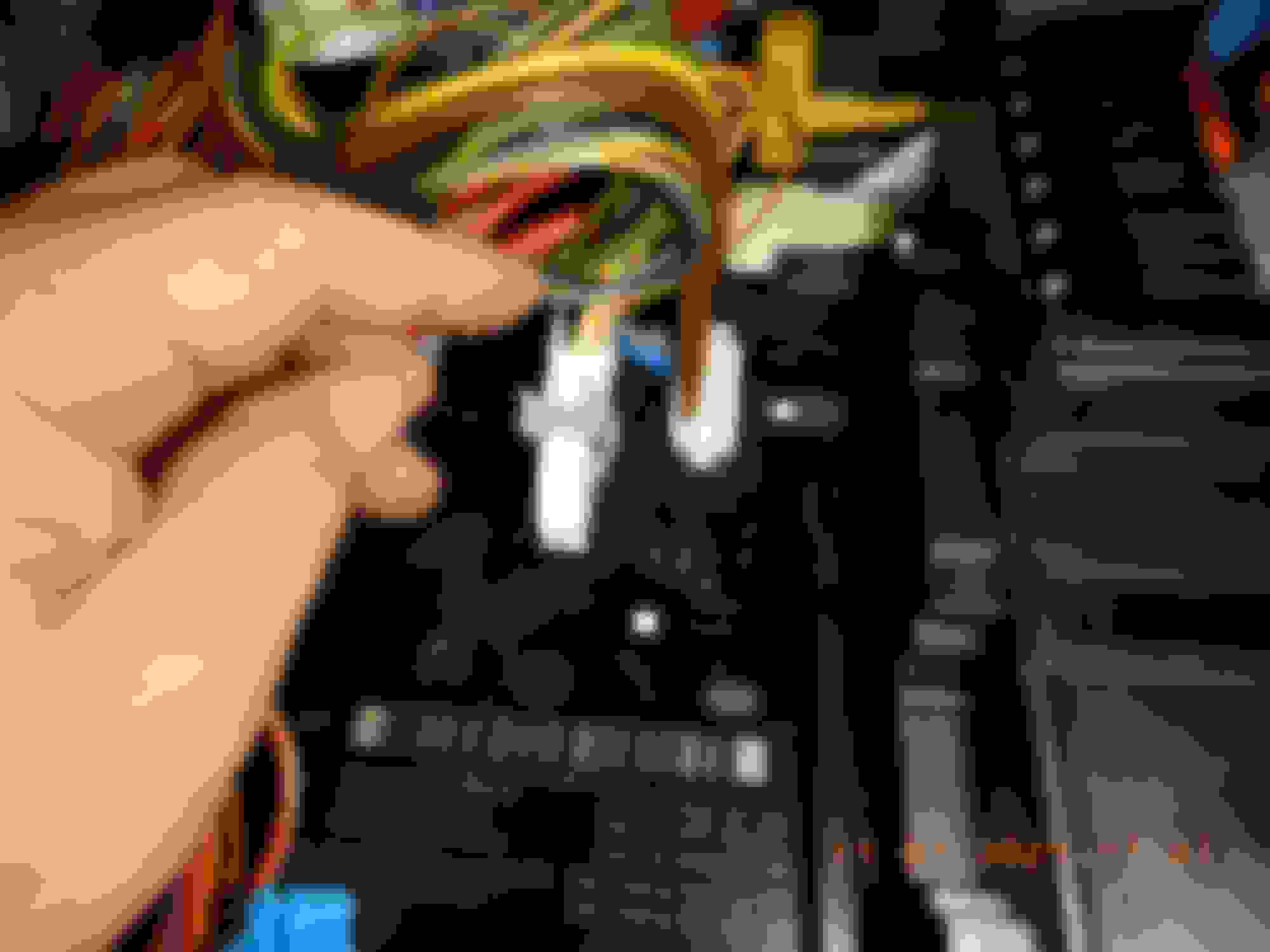
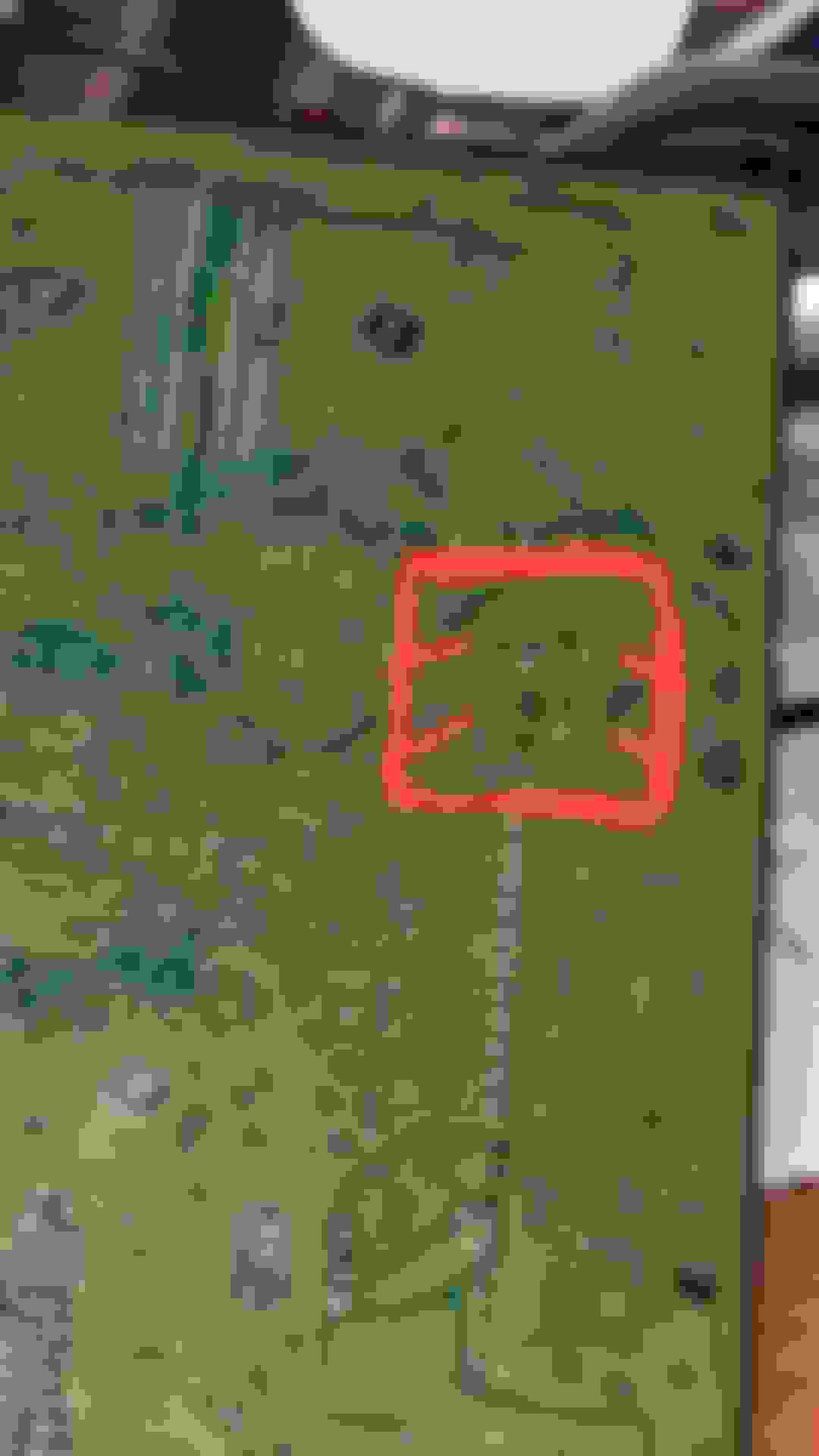
R-SAM COLD GND POINTS:
Where I am a bit puzzled is... I did get some nasty 12.3v AFTER initially fixing R-SAM pins and 2x GND screws BUT BEFORE this little SAM gathering party. This is what motivated me to go poke F-SAM to find loose pins.
R-SAM 2x COLD JOINTS
The only extra rework I did to R-SAM is these 2x super COLD SOLDERS with my 100W iron. They are likely distribution of either +12 or GND. This could be the elusive root cause I've been searching for.
The OUTCOME:
I really did all that work a week ago so yesterday the car was ready for a longer test drive ✌️
float voltage instead of deep discharge. ECO satisfied 8A burst showing AGM is pretty FULL... no more 80Amps yoyo: that's awesome!
This is a real cause for celebration... knock on wood. Hopefully the voltage management will be proven to work through all textbook conditions - Only time will tell 👍
"VOLTAGE CONTROL" and more:
When these computers are on their best behavior, the tranny shifts seemlessly like butter, the engine no longer has crickets sound from injectors, it has better low rpm torque with a distinctive stable idle hum.
Gas pedal is velvety smooth, very responsive to small demand with NO LAG between deceleration and acceleration... much easier to drive!
Touching keyless door handles noticeably has super fast response, like trunk kick.
Lux suspensions are better composed between soft and hard.
Overall it seems like CAN exchanges are faster, when driving or even when scanning the car through ODB2. Less bottlenecked CGW eases transfers lag??
F-SAM Bonus... future proofing:
The fastest way to waste your Front-SAM power distribution controller is to get it showered with rain. Benz are famous for swamping the interior floor with rain water for multiple reasons including when the glue of the roof seams matures.
the rear of the white plastic tub is left wide open to any rain traveling down A pillar.
I plugged that gapping hole with a piece of plastic foam as 1st kine of defense. Ultimately the whole wiring harness acts as a funnel. "plasti-dip" or something similar is needed to block any water from traveling down wiring into tub.
People have been wondering about the integrity of the F-SAM cover seal allowing water to ruin their SAM... now you know about this wide open rear entry.
+++++
Next cards to play ...
- more GND Points towards F-SAM etc
- more "loose pins be gone" F & R seats modules
ALL GND should be equals 🙂
Last edited by CaliBenzDriver; 07-05-2021 at 10:34 PM.
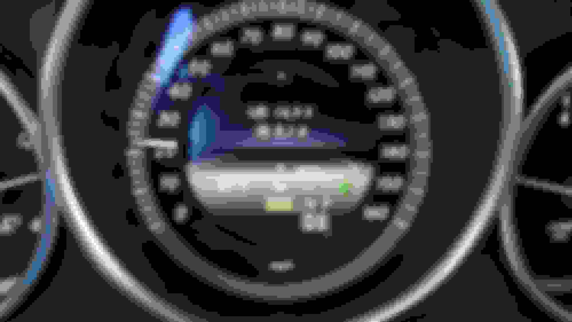
huh, i don't recall seeing that steering wheel icon above the [ECO]
I believe this icon is managed by the Distro+ controller (passenger footwell) when it's has the steering wheel under control, it glows green.
When the two front camera loose track of road markings or the electric steering input sensor report the driver has no steering input for a while then the icon changes to provide feedback.
Zero complaint with Distro+ module... it works well as designed around a normally soldered circuit board. This quality contrasts with solderless used in non-essential functions.
Congratulations on your success with the yoyo resolution. Excellent work!!!
If you were asked which of the two SAMs will you tackle for the yoyo issue, can you tell which one was the main (or only) culprit? Or do you think is a full approach, i.e. Front/Rear + all GRND point?
Thank you very much for all the details, and progress updates.
I believe I do have the solution in my hand but I am not sure what exactly fixed it -or it may be temporarily "fixed" due to battery reset......
If you are only concerned with deep discharge Yoyo and not about rain protection, you can ignore the F-SAM and concentrate only on:
- All painted GND posts.
- Solderless R-SAM connectors.
- 2x extra cold R-SAM GND solders.
It's easy to work around the W212 trunk. If you do these steps one by one you may find out which is the lucky one 😄
Last edited by CaliBenzDriver; 07-05-2021 at 10:41 PM.
I wonder if my RHD car , I can wiggle out the Front SAM without messing with wiper assy.
I am scared of fragile stuff, computer boards kind of stuff. My fingers are not delicate, it has lost its sensitivity in the last 5-6 years.
These potential : Bad-Contact and Intermittent-Contact is so real in electronics with connectors and what not.
My PC motherboard, until today, I lost 12GB of memory kind of permanently. I have 48GB and if I dont clean the contact points sometime I am down to 16GB.
This era was PC in open air dining room and I smoked like hell. 16GB was the lowest I had.
The last cleaning I managed to get back to 32GB for 2 years now, but I never could get the 48 GB back like when it was new to approx 4 years old.
This 32GB stability is PC already in a room, I stop smoking in the room by late 2019 and aircond run 18 hours a day.
Actually I am on a new motherboard, it is X79 Asus Sabertooth TUF of 2016.
I bought spare motherboard because I like my old 2012 3930K 6 core so much over my other newer 8 core CPU of 2014 and want to use it as long as I can.
I hate to change to Windows 10. I hate IT .... LOL.
So I hope to keep using this 6 core PC and Windows 7 till either my CPU goes kapoot and/or both motherboards goes kapoot.
I remember its 1st power supply Corsair HX1000 lasted 6 years ( 2018) and the capacitors not too healthy and I get bluescreen of death once in a while.
The points are, super stable voltage and good electrical contacts = peace & troublefree.
The coating you speak of, some marine electronics I used to open to take a peek in early year 2000s are already using those coating.
Imagine being a mini computer in a car aside from the engine ECU, like the font SAM in hot area and humid too..... man those are torture zones.
Since CAN bus is also an electricas signal , a voltage pulses, I think when you cleaned and improve connections, it maybe faster due to less error and hence less information re-send request wasting the already limited bandwith.
Probably Left Coast Geek can enlighten us on this CAN.
Cali,
Do you keep detailed view photo files of the front SAM power board top side (fuse) and back side ( soldering). Please share.
I want to see how the female contact points are for the fuses and relay pins and how good is the soldering.
I recalled when I was unplugging/inserting the fuses F74/F75 of headlights at rear SAM, the friction and compression is so weak, unlike ECM fuse 27 at front SAM which is so nice tight grippy insert and pull out.
Thanks....
The primary focus should be Rear-SAM because it is known to manage the float voltage when deep discharge happens, it is built with solderless pins and easy to work on.
The exact flip side is F-SAM: it's no pinic to get hold of and has no loose-pins. The one thing it needs is protection against water intrusion from the rear entry.
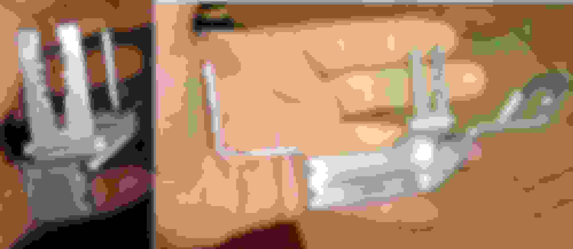
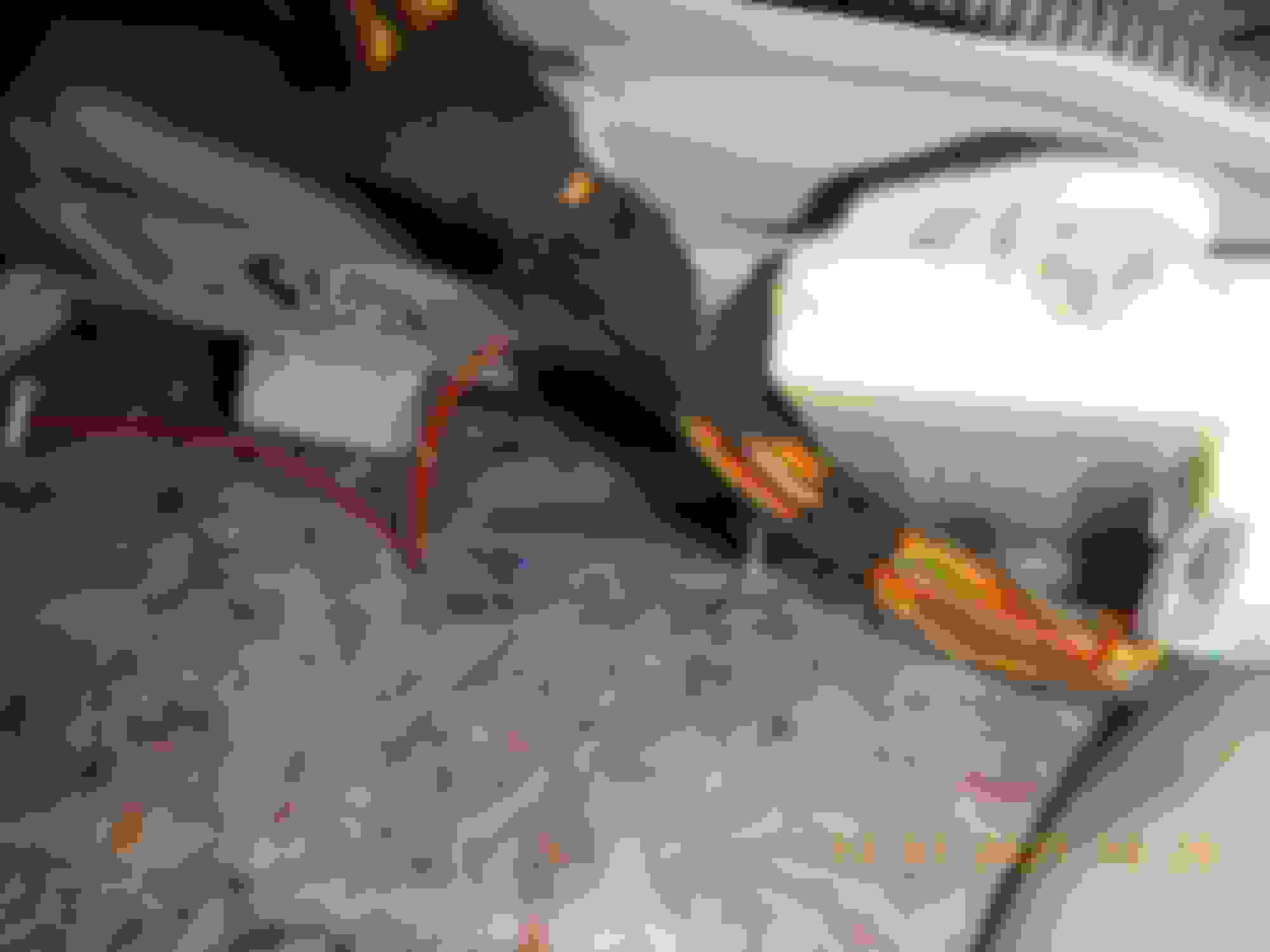
In order to slide out this module, pop the reusable plastic ball-joint between wiper and arm. Then you'll be able to manoeuver things out of your way.
F-SAM peeled out of the car pull at 45� while extracting connectors this little red one is the last one to pop
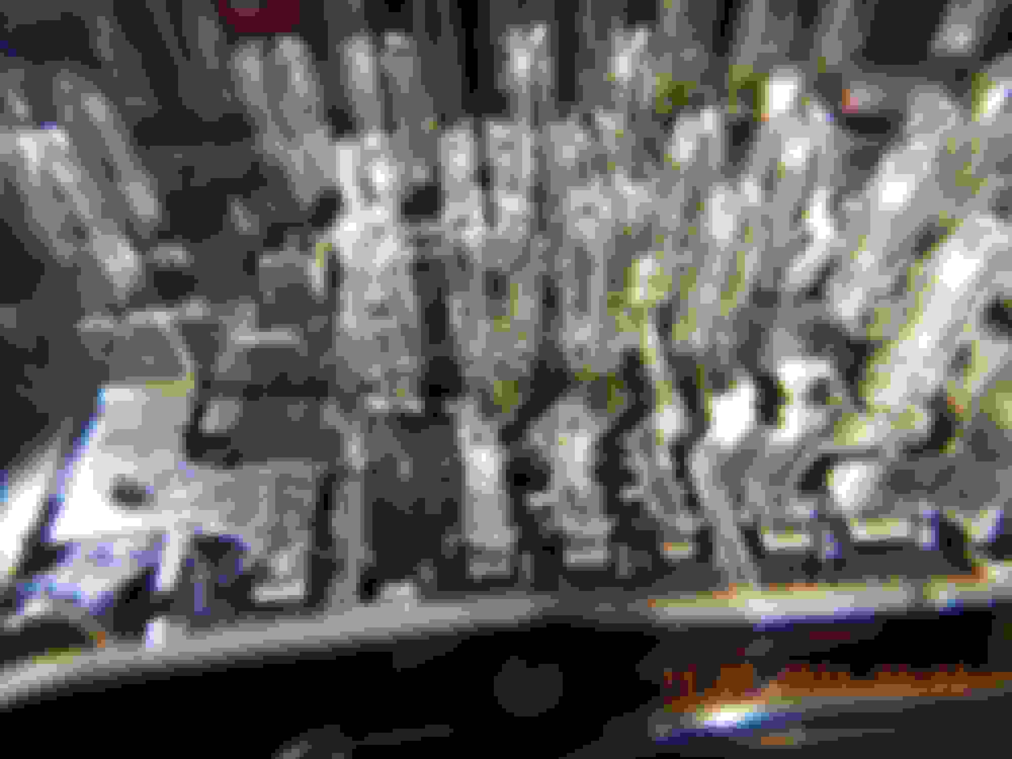
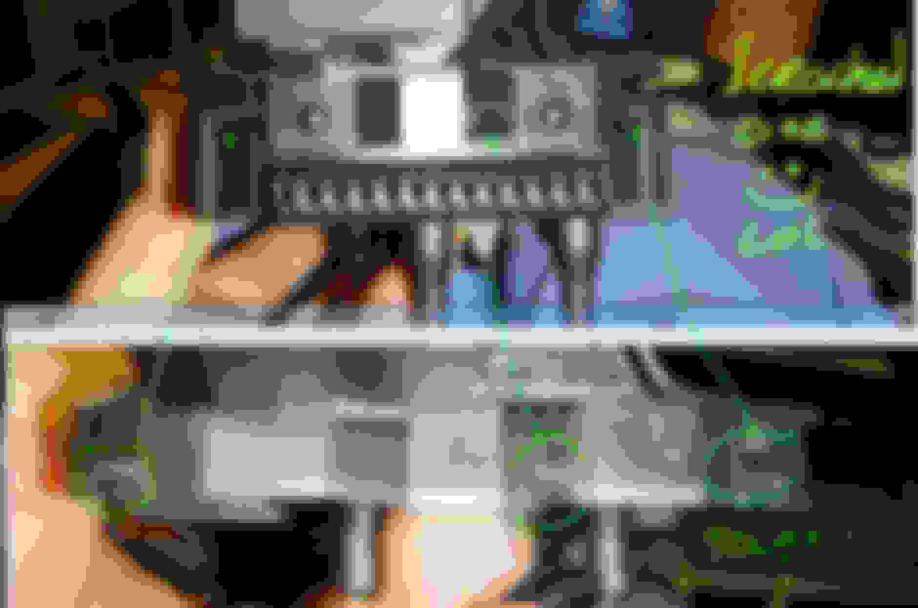
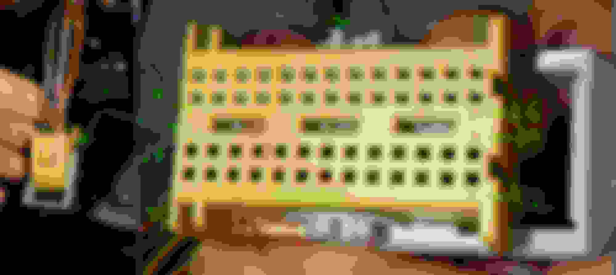
What these two SAM cousins share in common is the low insertion force fuse board. I am pretty sure an army of PhD's worked on that design because it's loose spring tension feels odd... hum 🤣
R-SAM fuse board R-SAM connectors
evidence marks of multi-brush female connector
For some reasons... Benz recommends not to use any contact cleaner on connector pins, so I did not. None of these 2 SAM's showed signs of heat or oxidation as of yet!
Working (P = U x I) is R-SAM duty:
The easiest way to keep DC currents within limits is to supply a good voltage. That is where R-SAM design is suposed to shine!
When the battery sensor is satisfied with AGM charge level, the voltage control logic goes into low power float mode at 12.6V.
R-SAM is then in charge of watching for high consumers. It bumps up voltage for A/C (14.0) and headlights (13.5) in order TO LOWER CURRENT.
Uncontroled discharge (11.3...) ramps up currents to consume nominal power.
I had no 5G today in Cali Sequoia National Park 👍
Asus is an all time favorite mobo brand. Have you noticed how modern systems are not really fast regardless of CPU core count?? Windows is actually driving with the brakes-ON... I can make it 25% faster and 15% more efficient. That is my science.
At some point I'd like to figure WHAT is bugging down or bottlenecking CAN transfers. These cars are built to be fault tolerant but I seriously hate lack luster performance caused by a single grain of sand. ✌️
Last edited by CaliBenzDriver; 07-06-2021 at 09:31 PM.
Thank you very much for the advice. Plans for Saturday are set , visit the trunk.
By any chance, did you take picture of the RearSAM module exterior? I wonder about part numbers, and LU/HW/SW codes to see if there is any correlation. A generic picture would be something like the
or
I have seen quite a few different ones already.. I guess upgrades from 2009-2016.
You can use my "50% off" method...There is NO need to extract the R-SAM fuse board to work on its PCB 👍
Only remove 4 connectors then separate by pressing on 2 large plastic tabs.
You don't need to unplug anything not attached to logic board shown below R-SAM control board
If this does not rain down happiness we're gona need to get creative... Run Xentry to lay eyes on a 3 horses race: Bosch - Hella - Hyundai.
For now let's wait for smart AGM sensor to finish relearning the battery after it got reset.
Last edited by CaliBenzDriver; 07-11-2021 at 03:38 AM.
A quick update:
- Got the RearSam out
- Picture below, coincidentally the exact part number as yours,
- Called the closest stealership to check on the price (in case I mess it up), and I was told the part number is obsolete and it has been replaced by
for a whopping $630, though online can be ordered for @$400->$500 depending on the site.
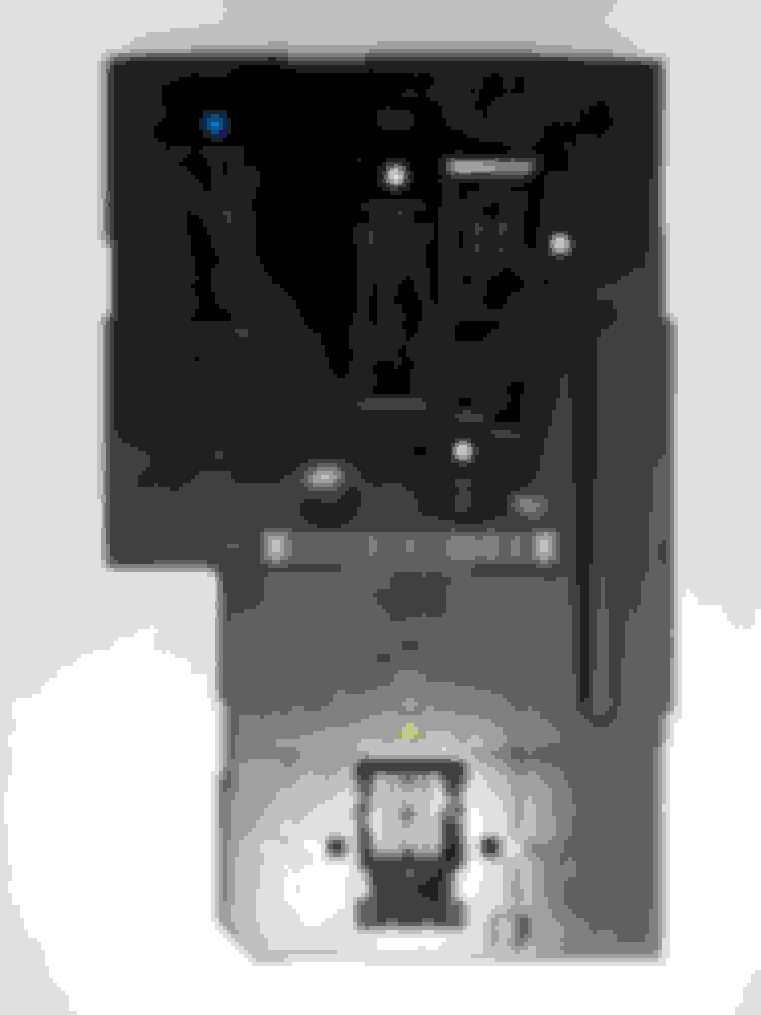
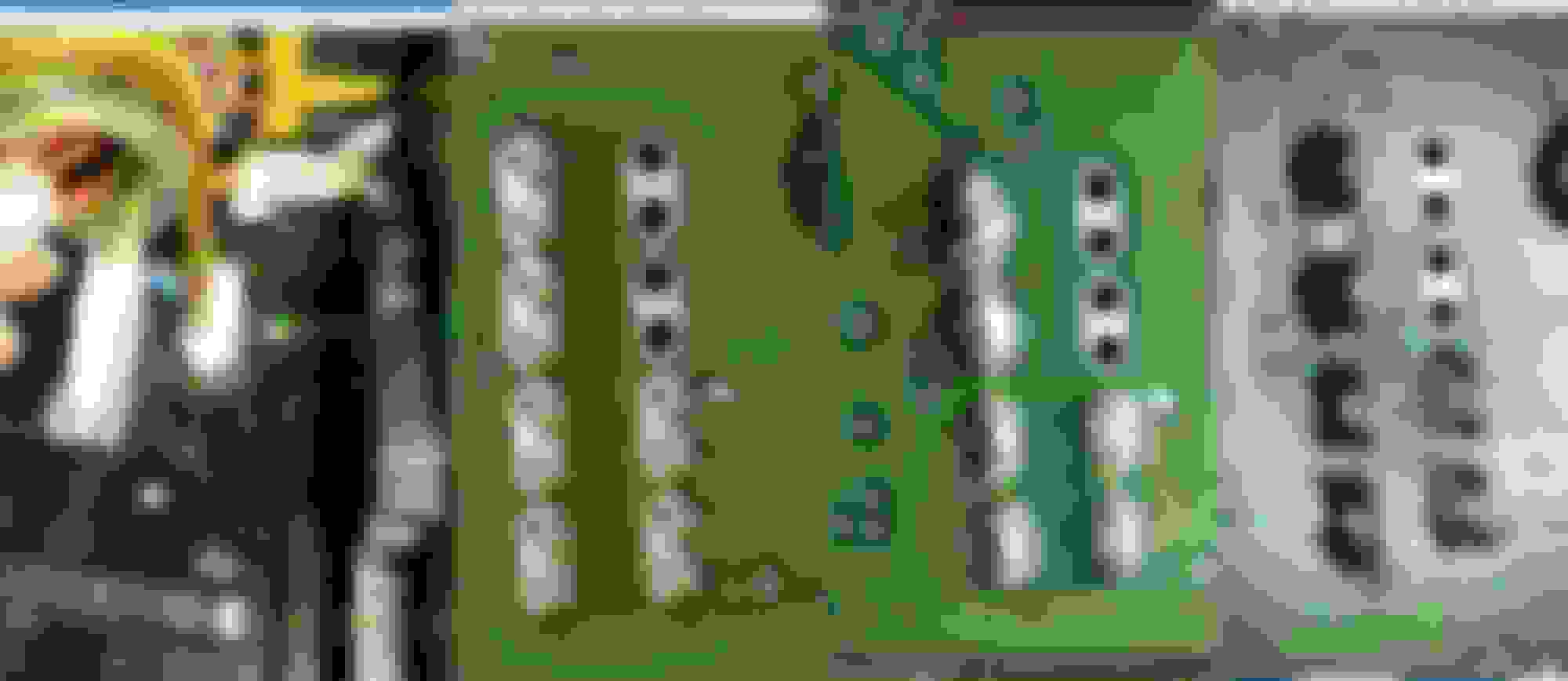
Here is the board view. you may notice the only soldered pins are at the bottom right near the 7014 stamped number.
Here is the region yours have the "cold ones" zoomed in.
I was unable to solder a sample board, so I do not want to mess with this one.
In the meantime, I reassembled it until I practice my soldering skills a bit more, or blame it on the poor quality of tools.
Two thumbs up! 👍👍
You've seen how easy it was to get hold of that R-SAM. It's actually hard to mess up soldering dumb pins because they are not heat sensitive like active chips that can get fried with overheat.
To produce good solder joints THE KEY IS TEMPERATURE plus the soldering wire itself. That's why you don't want a $5 disposable solder iron from the bargain bin. You want a 60w temperature regulated to quickly climb to temp range and get back up there between each solder demand.
The trouble with "cold joints" is they sink heat faster than the iron can produce it. So you approach carefully with a bigger caliber: 100W unregulated to deliver all the heat for good results.
There may be ways to do things differently, I am just sharing my own perspectives. When soldering you have to be your own judge to decide what is a satisfactory solder joint, just like when you torque your wheels by hand.
Don't feel tempted to skip or do a cheap job when you're fixing your own toys... instead "Just Do It!". Through-holes next to 4 pins
In my eyes these 5 through-holes are an indication there is a HIGH CURRENT demand or a requirement for low resistance. This group of pins and plated holes are the same connection point. Regard this spot as special, not as a PITA. You're here to finish a job where Hella cut corner. FIXING THESE COLD PINS IS AS IMPORTANT AS THE PAINTED GND SCREWS. A bad GND connection allows the reference voltage to float erratically. All voltages are measured trusting the same common GND. It is supposedly not affected by anything including high current. Thus the reason why power and control paths are distinct.
The theme with solderless-pins is they are apparently not used in ESSENTIAL modules (ECU, F-SAM, CGW, Brakes, SSR, Distro...) only secondary peripherals that are expected to get worked on.
However to me both SAM's are top VIP and everything that can flood the CGW Gateway as well, regardless of priority ranking.
✌️
Last edited by CaliBenzDriver; 07-11-2021 at 03:35 AM.
Reason: through holes
On a sad note. I just discovered that the Benz spare wheel plastic base is soooooo crappy in strength.
I must have over-tightened it last time I checked it.
The base is the one holding the male big plastic stud.
.
I have the keyless-Go, but not the kung-fu kick one, the manual by hand one for rear trunk.
So no small white plastic box with extra logic board like yours Cali.
Holy Cow, these cables are so fine. Look so fragile them 0.5mm ones. The last time I messed with wiring assy was old Toyota, so cables are FATTER.
Last edited by S-Prihadi; 07-11-2021 at 09:58 AM.
Reason: add info
Cali, how to remove the plastic body of rear SAM power board safely ?
01. How does this metal top frame comes out from the plastic body ? Pure friction insertion by MB or any Indiana Jones boby-trap I should know about ?
The bottom part. How is best to undo the lock/latch. It is so tight. Unlike the side ones big and forgiving.
Thank U Master Yoda
Use two flat screw drivers to pop the big metal bracket, litle by little it will come up rocking over over a 2 minutes span.
No Benz trick in there to access the fuse board... you are going to be amazed by the low insertion fuse holders 🤣
When soldering your pins make sure you don't bridge any open gaps between non-connected pins. Visually check before vs. after so you do not create any short-circuit. To help you take close-up pics of before/after to check your rework.
I did not mess with any of the loose fuse holders... I don't know what can be done with that except prevent high-currents. You could fix any burnt holders with an external bypass fuse soldered back to the fuse board. My fuse board looks in mint condition. (80Amp ALT->BATT surge only goes across the preFuse, not SAM's).
👍
++++++ Hidden R-SAM Fuse Link:
I should note... I saw a hidden fuse internal to the fuse board (120A?). It's a skinny metal trace non-replaceable that looks like a distinctive "S".
It likely protects fire in rear accidents. .... how about that!
Last edited by CaliBenzDriver; 07-12-2021 at 02:38 PM.
Reason: fuse pic
For Juan or next interested person.
Rear SAM powerboard is not worthile to open up. Some collateral damage occured to mine, well cosmetic only...but UGLY !!!
I failed to observe Cali's photo properly and I thought it is made of dark blue typical fiberboard PCB, it is not.
The overwhelming shine from the bus bar tricked me ( excuse for old eyes )
It is a simple thin plastic layers squeezing/framing/holding thin nickle plated copper bus bar or copper trace.
There is nothing to solder. Unless you want to see how it looks like, no need to open up the plastic casing covering it.
Fuse receiving side
the Azz/Bottom side
Side view
The female pins tulip shape, the one holding the fuse or relay male pin/leg
The jaws of death - this is one of the reason I had cosmetic damage on the plastic casing removing the top part steel mount. Yes, me hand and fingers not delicate too.
Another excuse...... from me. LOL
=========================================
Tips.
Some dual push pins are actually from 1 connector blade.
I was so confused at first when soldering the pin one by one, how come the heat from the solder tip gone away so fast at this super small pin ???
Dang, the other pin and the thick blade swallowed most of the heat.
This is the biggest dual pin blade.
I soldered them together...
Dang...my hands/fingers are not stable
Even with magnifying glass............. these pins are too small for my hands.
But I can manage... slowly. With lots of rest period in between to sooth my eyes.
For Juan or next interested person.
Rear SAM powerboard is not worthile to open up. Some collateral damage occured to mine, well cosmetic only...but UGLY !!!
I failed to observe Cali's photo properly and I thought it is made of dark blue typical fiberboard PCB, it is not.
The overwhelming shine from the bus bar tricked me ( excuse for old eyes )
It is a simple thin plastic layers squeezing/framing/holding thin nickle plated copper bus bar or copper trace.
There is nothing to solder. Unless you want to see how it looks like, no need to open up the plastic casing covering it.
the Azz/Bottom side
The female pins tulip shape, the one holding the fuse or relay male pin/leg
========================================
Tips.
Some dual push pins are actually from 1 connector blade.
I was so confused at first when soldering the pin one by one, how come the heat from the solder tip gone away so fast at this super small pin ???
Dang, the other pin and the thick blade swallowed most of the heat.
This is the biggest dual pin blade.
I soldered them together...
Dang...my hands/fingers are not stable
Even with magnifying glass............. these pins are too small for my hands.
But I can manage... slowly. With lots of rest period in between to sooth my eyes.
Will report more when done.
You're doing all right making progress with your soldering. Try to move to a different pin every 3 to 4 second so you don't overheat the PCB.
Solder wicking happens because of the built-in flux. Once your flux is cooked off, nothing can get soldered together. You have to dump existing solder to start over to get new flux to work for you.
Left good - Right side bad!
looks like Big'O hidden fuse ??
Last you want to clean the board to remove any flux leftover. Use toothbrush with Alcohol (+Acetone) as needed. This help reduce oxidation issues later on. Brush/spray on a protective coat once you are satisfied.
🤗
Last edited by CaliBenzDriver; 07-12-2021 at 02:11 PM.
also, solder is attracted towards the heat. you want to make sure your temperature controlled iron is heating BOTH the circuit pad AND the lead, and touch the solder to the other side of the pin so it gets pulled around the pin and flows onto the PCB pad.
I believe the kung-fu kick sensor belongs to the trunk closer module.
Check if your Keyless-Go is located high up above R-SAM facing towards the outside. (I don't know exactly where all the multiple KG antennas are located... they seem dependable).
You'll see 3x 10mm screws holding the bracket above R-SAM: KG fastened to its holding bracket
This module is worthy of attention: it has a dual row of solderless pins, it has power handling components and manages the chatting between the key and all the locks.
Last edited by CaliBenzDriver; 07-12-2021 at 05:24 PM.
Thank you Cali.
I thought no leg kick kungfu open trunk option, means I do not have the white plastic module.
Must check, that lone red wire, what does that serve ?
Is that the antenna for keyless go white module ?
Its too tight a space for my head, so only camera view inspection this morning.
CAN BUS B ( Interior CAN ) of N10/2 Rear SAM
Since I am checking where the 2 wires are connected into Rear SAM, might as well share the info here.
.
.
.
NOTE : I have not yet physically confirm that pin 30 dan 31 is for those CAN-B wires. I am only refering to the schematic and trying to see how MB twisted the CAN wires .
I don't want to trust a 100% any schematic from MB until I cross check wire color and physical pins on the connector.
0.35mm baby wire ............damn, so small and fragile.
For those not familiar with German decimals.
2.5 (two point five) to them is written as 2,5. So 1 million dollars zero cents is written for Germans as $1.000.000,00 for US as $1,000,000.00
Actually my country is the same as German decimals, but I am so used to the DOT and not COMA.
MB WIS is kinda crowded of these decimals mix up, some use DOT and some COMA.
 06-27-2021, 01:58 AM


 by late 2019 and aircond run 18 hours a day.