When you click on links to various merchants on this site and make a purchase, this can result in this site earning a commission. Affiliate programs and affiliations include, but are not limited to, the eBay Partner Network.
The landfills are pretty much full so why not simply fix our priceless modules if at all possible ?
To fix a defective Benz module you either need a new unit SCN coded with Xentry
-or if you're lucky, you can take 10mn to finish the soldering job left out in some modules. Your best chance is not to wait for a failed modules that are hard to fix without schematic and proprietary parts. 😏
This thread is my contribution to get "the best or nothing" closer to reality. The collection of these details make a remarquable difference in network stability. 👍
Hands on modules fixing :
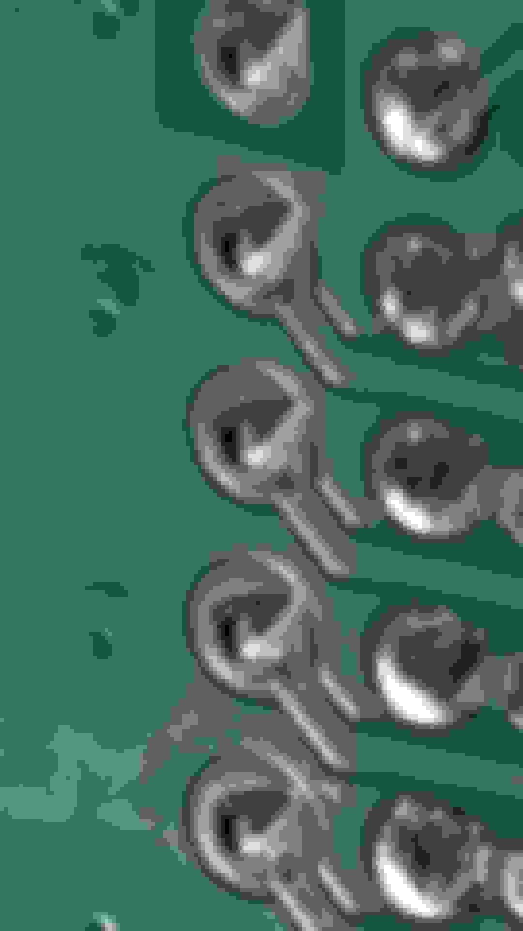
seasoned pressed-pins showing heat trouble
All car electronics are not built to the same standards. Some modules are bullet-proof (ECU, TCM), some are recalled (electric Steering) while others are kept unrepaired during warranty (KGO, DCU, RFK,...) don't ask me why!
Main modules are made reliable with soldered connectors on gold plated boards, while secondary modules use unsoldered pressed-pins.... 🤣
What happens is overtime a circuit weakness makes it subject to additional stress from oxydation, power surges and heat. This causes components to age prematurely and create intermittent chaos: the "could not reproduce!" pickle.
My updated list of PRESSED-PINS MODULES:
Trunk lid puller module << easy!
Trunk buttons module << easy!
Windshield rain sensor
Windshield temp/humidity sensor KeylessGo A2129005422 << easy! R-SAM 2129009722 by Hella << simple.
CCU is HVAC controller (34 pins) << easy! LowerControlPannel: (3Pins) <<< simple
NORMALY SOLDERED MODULES :
- Audio Power Amplifier in trunk
- OCP module overhead buttons
- DistronicPlus by Continental
- CGW (IGW A2129004724) by Lear
- 110V Outlet inverter
- TCM?
- LP Fuel pump ctrl (Conti. A212 900 03 06)
- mBrace - F-SAM (See YT. video about rework!) by Bosch-
- Driver/Psg Seat modules (crusties!)
- Headlights switch
- Instrument Cluster display
- CMD Display module
CANDIDATES LIST:
Rollup blind Rear window << DCU Door controllers x4 Conti. TPMS .. over rear axle location??<< Amp of rear woofer speaker
Side mirrors (LIN?) Headlights LED module? (See https://xenons4u.co.uk/a2059004230-l...dule-unit.html)
Bumper 4x radar sensor modules ?
(Steering column lock module??)
(Ignition key module??)
(ECU ....master of all: should be an A_Grade!)
(Accelerator pedal... is sealed!)
(Cameras front/back: sealed!!)
(COMAND head - needs 5+Hrs!)
>> Other missing suggestions..?
Index of Fixes by Posts: (More details are available in each post)
#03: RainLightSensor, TrunkPuller module
#11 ABC's of PCB rework tools
#...WIP:in progress #99: iCluster, CmdDisplay, LightSwitch, Clock #100: Halloween look
++++++++ ! Advanced section ! +++++
My Top Down priorities : This thread is about uncovering problems and finding solutions, not about deploying a missing TSB. All of this is EXPERIMENTAL by nature, guidance welcomed.
At this point, I am begining to suspect something is impacting my ECU work. I am NOT 100% positive what it is (FW bug, CAN, Pins, GND,...) - I know it's affecting timings.
Previously thought... the best way to rework the pins condition is to begin by fixing both SAM power managers followed by :
- perform preventive rework on VIP modules (Ignition, Fuel pump, KG,...) and BRIDGES to easily avoid LimpMode surprises down the road.
- consider secondary modules (HVAC, doors, seats, ...) and others as they begin to acting up.
✌️
All CAN Networks are different:
The powertrain relies on CAN-C to be functional otherwise you get a limp-mode. Other CAN's (B, D,E) are not mandatory for engine. So it's key to pamper ALL CAN-C members to prevent serious disruption.
Computing latencies between software and distributed hardware has been one of my top interest for the past 2 decades.
Don't assume that because CAN are purposely separated they don't interact and everything is well. Nop! Actually problems start when fetching asynchronous data. Peripheral CAN modules use network bridges to swap control data. When a bridge is bottlenecked, the traffic messages pile up and delays (Keyless door operations!) - In my E-350 this is true for Engine Engine timings, Tranny shifts, Suspensions kicks, Distro+ response, neutral Steering center... This vehicle fault-tolerence allow it to run with derated performance but it works far better with unimpacted CAN peripherals.
TIMINGS: Case of the rear wheels kick + more:
When the control loop of the dynamic suspension suffers latencies, the magneto-electric strut commands arrive milliseconds late instead of microseconds, this makes struts dampening harder or softer but in the wrong spot because the car has traveled a distance.
As it turn out, this delay emphasizes road bumps instead of ironing them flat. It also makes front wheel steering a bit unstable instead of planted straight.
When computers are responsive, the car rides smooth and flat like a flying carpet with zero bump -else it feels like standard shocks that transfer every riddle.
Engine timings are injectors, ignitions and valves based on ticks by CKP. ECU is capable of detecting CKP jitter and figure witch cylinder lean mixture is misfiring.
Tranny timings can easily be felt in shift quality. Responsive ECU/TCM computer team yield totally seemless shifts, always in the right gear. Busy computers yield long slipery shifts, out of time and with some clutch bangs and a heavy elephant in tow. Once you've witnesed the difference, it's amazing.All this is not simply voltage related (11>15v), it's related to ECU signal timings. Realtime systems are sensitive to delays.
Does this correlate with some of your experience?
++++ Big prize question: Networking paths
Are there any solderless module acting as Bridges? In other words: Who are the BRIDGE modules:
"N73" bridges CAN-B with E1
"A1" bridges CAN-B with E2
"N10/1" bridges CAN-B with E1; E2; LIN1(N72/1)
"A1" bridges CAN-B with E1
"A2-A40/3" bridges CAN-B with A; 'MOST/Medias'
ECU bridges CAN-B with C
(Other CANs too)
Last edited by CaliBenzDriver; Sep 27, 2021 at 10:38 PM.
Reason: OP list update - Some Pics move down#3
You owe it to yourself to fix this basic trunk module!
These fat solders are often better than none
Trunk closer pins got seriously oxidized from drop voltage heat.
seasoned pins show heat trouble
-------------------------
Originally Posted by S-Prihadi
Dang............ is that on your car Cali ?
Or a collection from few people improvement projects ?
I think the soldering dip machine them OEM use were on "stingy" mode setting.... Russian roulette is the result.
Yes, that is the original sanitization project of my '14 W212 fixing known issues ("dry mechanisms" and now "solderless" too)
Now my Trunk closer function works like velvet AND the "kick to close" works reliably unlike new.
Originally I targeted all mechanical modules in the trunk based on ease of access. I discovered the unsoldered pins from multiple module suppliers so that tells me it's not a mistake but a sort of design feature. I can see how having contact pins mechanically inserted in PCB may better than only soldered with weak ROHS alloys.
What happened is they stopped using the plastic female connectors that were used to hold all those pins !!
BEWARE that when you are casually removing module connectors you are directly tugging on each individual pressed-pin... so double check the connector's mouth to see if any pins got released during disassembly - This step can keep you from pulling your hair later. FYI: So far I have not have pins come out dislodged. They do work with minimal drop voltage after being soldered.
Last edited by CaliBenzDriver; Sep 12, 2021 at 04:46 AM.
Reason: remodeling OP
So its been sloppy job with soldering since early 2000 ?
Mind you, the poor soldering is at the Power Board of Front SAM, where all the fuses are plugged in-to.
That is equal to loose/poor connection at copper bus bar if analogy is a home Main Electrical Power Distribution Panel/Board 110/220V split single phase 3 wires for USA and 230/380V 3 phase 4 wires for my region.
Imagine, if these boards are the multilayer type, oh boy, we will get intermittent contact so mysterious if the poor soldering or flimsy copper trace occured at middle layer.
We then simply mark it as unpredictable intermittent issue and get a new module instead. https://www.allpcb.com/multi_layer_boards.html
Thank you Surya! This must see video answers a lot of questions 👏
Now you've just increased my rework list to include the F-SAM.
First I'll fix my R-SAM to see if it cures the voltage yoyo.
I wonder if the ECU is graced with this type of solderless connectors..?
I am amazed at how they even carry the high current to a 40Amp fuse with these PCB connectors 🤣
The HVAC module that works near cold evap coil gets condensation from being cold during drives. That's going to be a good candidate for someone's fixing.
----- Edit---- Video evidence
In the video the dual board F-SAM shows a lot of nasty oxidation bridges between traces and solderless pins.
The modules powered-on 24x7 are evidently missing a protective coat on both sides so the narrow gaps can't get a chance to work a bridge.
The video shows how to replace an HVAC silicone chip. The SMD chip was blown by high current from the coolant valve being hard to move with a rusted cable.
These actuators should be a regular maintenance item around 80kMi✌️
Last edited by CaliBenzDriver; Jun 17, 2021 at 02:28 AM.
Reason: 2Hr YT Video
Some of those soldering failures can be attributed to the magical properties of lead-free solder, required by law in Europe (RoHS) and probably elsewhere for years. Lead-free solder requires high quality solder with voodoo flux, perfect temperature control at the instant of soldering, complete cleanliness of everything involved, and several other conditions, which probably include the correct phase of the moon and proper barometric pressure.
If you think that the joints that look bad are inexcusable, I've seen examples where joints go bad that are seemingly perfect and no magnification at my disposal will reveal why they won't conduct. A retouch with old fashioned TIN/LEAD (possibly illegal in some areas) solder will cause them to magically work.
A positive that modern surface mount electronics has for automotive use is that the parts are smaller and have less mass, and are less likely to fail from mechanical/connectivity issues. This, of course, assumes that the supplier hasn't cheapened out on the thinnest possible PCB and/or has taken steps to mount the board in such a way as to break up harmonic vibrations. The link below is an interesting discussion by experts on the lead/lead-free subject.
Keep in mind that automotive electronics are incredibly demanding due to extremely wide operating and "storage" temperatures. Combine that with differences in coefficient of expansion of the solder, parts, and boards...well, it's tough.
If these cars were made with 1980's electronics quality, I'd guess that the resulting cars would have a MTBF (mean time before failure) measured in tens of hours.
Last edited by strife; Jun 15, 2021 at 05:58 PM.
Reason: Added comments
it is true that automotive environment is challenging for electronics but compared to aviation, aerospace or military it offers fair conditions.
I am pretty impressed with the SMD components on microcontroller boards, ROHS wave seems to have been mastered.
The big contrast is unsoldered connector pins and unprotected PCB's to prevent troublesome oxydation.
We have seen how even the harness use crimped connectors that are nicely soldered to be reliable. The PCB pressed pins I am sure offer some cost advantages and can easily be made more reliable with a little soldering 👏
Last edited by CaliBenzDriver; Jun 15, 2021 at 10:29 PM.
Some of those soldering failures can be attributed to the magical properties of lead-free solder, required by law in Europe (RoHS) and probably elsewhere for years. Lead-free solder requires high quality solder with voodoo flux, perfect temperature control at the instant of soldering, complete cleanliness of everything involved, and several other conditions, which probably include the correct phase of the moon and proper barometric pressure.
If you think that the joints that look bad are inexcusable, I've seen examples where joints go bad that are seemingly perfect and no magnification at my disposal will reveal why they won't conduct. A retouch with old fashioned TIN/LEAD (possibly illegal in some areas) solder will cause them to magically work.
A positive that modern surface mount electronics has for automotive use is that the parts are smaller and have less mass, and are less likely to fail from mechanical/connectivity issues. This, of course, assumes that the supplier hasn't cheapened out on the thinnest possible PCB and/or has taken steps to mount the board in such a way as to break up harmonic vibrations. The link below is an interesting discussion by experts on the lead/lead-free subject.
Keep in mind that automotive electronics are incredibly demanding due to extremely wide operating and "storage" temperatures. Combine that with differences in coefficient of expansion of the solder, parts, and boards...well, it's tough.
If these cars were made with 1980's electronics quality, I'd guess that the resulting cars would have a MTBF (mean time before failure) measured in tens of hours.
Great info... thank you Strife
Wah...poor surface tension for lead-free solder. No wonder lots of sinkhole.
it is true that automotive environment is challenging for electronics but compared to aviation, aerospace or military it offers fair conditions.
I am pretty impressed with the SMD components on microcontroller boards, ROHS wave seems to have been mastered.
The big contrast is unsoldered connector pins and unprotected PCB's to prevent troublesome oxydation.
We have seen how even the harness use crimped connectors that are nicely soldered to be reliable. The PCB pressed pins I am sure offer some cost advantages and can easily be made more reliable with a little soldering 👏
@CaliBenzDriver thanks, this is great information. Can you please post photos and product information (links) for tools and materials to make the solder repairs?
A photo of your workbench would be great, with your comments added on what tools and materials are shown in the photo.
@CaliBenzDriver thanks, this is great information. Can you please post photos and product information (links) for tools and materials to make the solder repairs?
A photo of your workbench would be great, with your comments added on what tools and materials are shown in the photo.
my five versatile irons
SCOPE:
EVERYONE who can hold a writing pen is pre-qualified to fix these super trivial problems.
My disclaimer is SCN'ed Benz modules may not be the cheapest way to make your first mistakes. You may want to watch a couple video and practice soldering on old electronics.
It's not hard to either do a good job -or screw more things than anyone dare to fix.
The real key is knowing what you are doing and when to stop putting heat on a particular solder joint. Heat is the enemy of PCB layers can delaminate when way overheated.
STARTER:
I recommend you should practice taking apart the windshield rain sensor under the 2x MFK cameras... then later concider fixing your 2x SAM'S as a graduate level. This way you car will still be driveable regardless of your progress.
The scope is simple stuff because...:
-1- We are only dealing with soldering the PINS to the boards and adding a protective coat to prevent oxydation between traces (<<--- battery drain while parked!).
-2- We are NOT dealing with any of the tiny SMD parts or troubleshooting dead functions.
-3- I am open to fixing any additional problems we can uncover. These worldclass boards are *nearly* perfect.
SKILLS ...
you need to be focused and careful around delicate goodies. Anything you screw with may cost ya. So find the pins, solder all of them carefully.
Make 100% absolutely sure NONE of ALL your solder job is bridging over to adjacent traces! Luck and electronics never mix.
The more advanced steps may includes resoldering high power components when your eyes understand what you're looking at: logic vs. power control.
High current spikes are a sever stressor to all weak points. I'll point some of that when I fix more modules. So far the various solders quality I've winessed have been A1 professional.
TOOLS:
Nothing fancy that makes this expert only. Mostly garden variety tools. Typically you buy an iron that match the job you need to work on.
1-- Mid-size and full size solder irons to put out a lot of heat. (if you own a SMD rework station you know it's limitations) - Here we need to put out more heat than the board GND planes can absorb. So for this type of job I use a 60w iron and 100w as a backup if needed. The delicate irons are out of their league with heavy solders. You need an iron tip that can transfer a thermal punch, not just reach a temperature for SMD's. The PCB pins are going to suck the heat out of your iron tip.... so here my go-to iron is a mid-sized 60W Weller 336B with a regulating tip.
2-- Regular electronic solder with built in flux. That's were you do not go cheap.
3-- Magnifying lens 40x to get a close look for bridges and cold joints.
4-- Conformal PCB coating to protect oxydation and condensation.
You don't need a good looking $250 setup... unless you want to swap the module's own EPROM .
Xmas in June: great $18 starter kit 👍
TRICKS: <<-- the interesting stuff
Realise the problem we are fixing here is one of the reason the OEM went solderless:
IT'S NOT CHEAP TO MANUFACTURE GOOD GND SOLDER JOINTS WITH MACHINES... else they would still doing it the old way 😎
A lot of heat is required and small parts do not like prolonged heat. I know this used to be commonly done but technology has evolved to become what we are dealing with.
By relying on pins mechanically inserted in the board, manufacturers tried to eliminate the issues with bad solders. So bad COLD SOLDER JOINTS is what you will be up against when soldering pins in large GND planes. I mention this because some solders points will go amazingly well and others will give you hell sinking all the heat away from your too small iron tip - That's when you make a list and come back with your bigo-100W to solder all the cold spots at once. Don't idle your 100W iron for 2.5 Hrs, use it for 10mn 🙂
BONUS:
It takes some doing to extract a module out of your W212 and land a naked board out of its addembly on your bench, right?
So go ahead and take the opportunity to completely assess the specific board you're dealing with.
Any brownish signs of heat around a power path (MosFet, trace, pins,...), corroded traces, bidged gaps, liquid intrusion, discolored solders, loose or missing pins, unsoldered SMD's, etc... pls share any missings inspection items you like to go over.
The electronic OEM's for this car have been allowed to design modules with multiple failure points: (narrow gap between powered traces, unsoldered power pins, uncoated PCB besides basic mask, bare bone 16v caps,...)
By the time you get done, you want to be fairly confident you won't need to see that module again. It's better to spend 10mn now than couple hours later unbuttoning it all again.
Troubleshooting kaput electronics without a schematic is a time consuming art with a mixed success rate. That's why I strongly favor preventive maintenance to avoid nose bleed surprises.
small forest of solderless pin 🤣
-----EDITS:
In my crosshair: trunk modules are next.
Last edited by CaliBenzDriver; Jun 17, 2021 at 03:00 AM.
I've been dabbling with electronic components for almost 50 years, and the idea of "pressed-in connector pins" is new to me. But apparently, on high-volume components and a lot of engineering and capital manufacturing equipment, it can be done, and does work.
As everyone guessed it is a cost-saving and somewhat environmentally friendly measure.
With that being said, just like anything else, it can fail. As some of the photos in the original posts show, at least solder, leaded or lead-free, can act as a barrier to corrosion on the critical junction between the pin and the plating on the boards. Of course, solder, leaded or not, can crack under stresses you might see in a connector. On a consumer/industrial product in a house or factory, corrosion isn't likely, but in a car...
This a fairly interesting technical document on the subject;
10x better... when new 🙂
Press-fit is said to be more reliable than soldered connections because it eliminates ALL temperature issues with cold solders.
compact field of pins
Catch-22 limitation:
Press-fit pins and conformal coating don't mix easily without masking sensitive parts. The isolating film should not be allowed in the contact between the pin and plated drillings.
I don't think there's a way to solder the tall side of pins, only the short side yes. Soldering both sides would allow us to apply protective film
Because of that limitation we can NOT brush on any protective film (not spray) near the base of unsoldered pins. Everywhere else yes, we can prevent oxidation between coper traces.
This type of detail can mess things up wholesale.
SAM oxidation samples:
Here we have 2 examples of SAM deterioration that can be easily prevented (samples from Youtube).
Oxidation bridges between SAM pins
Oxidation bridges between SAM traces
Last edited by CaliBenzDriver; Jun 18, 2021 at 08:24 PM.
Reason: SAM samples
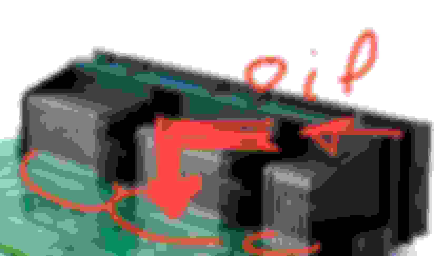
Gents, i think I just extended this simple repair to include the "OIL IN HARNESS" nightmares!
Yesterday in my post directly above, I was talking about carefully not allowing protective film near the unsoldered pins....
BINGO!
Guess what the engine oil in harness does to the contacts of press-fit pins??
It isolates them and interfere with low resistance necessary to pass current and signals !
Press-pins: 10x better or $10k rat trap?
How to fix that sticky mess:
You start at OP and clean the oil with alcohol or acetone ($5/Qt from Home center) from the ECU
Save your money and time:
You don't need to bother dealing with all the engine leaky plugs (solenoid/sensor, actuators...)
Soldering is king !
Fear not:
The harness oil repair, was a juicy failure mode... now cheap to untangle.
🤗
Why do you think the ECU is hosted in the hot engine bay instead of inside the cooled cabin as in Japanese cousin's...
shorter wiring, faster results ???
Last edited by CaliBenzDriver; Jun 20, 2021 at 04:10 AM.
Reason: organized information is what creates Knowledge !
Yesterday I met with CGW (the top VIP that interconnects all the CANs) + Distronic module who are both state of the art reliable good guys.
Today I got to work on the KeylessGo module... it's a quick and easy rework with about 30 unsoldered pins.
rear right trunk KGo easy to solder pins soldered on the right vs. untouched left side...
4 power parts acting under a microcontroller
Fixing the connector on the KGo board is basic entry level. 30 pins carrying current for the power silicon actuators. It would be a shame not to make this better while the electronic is still functional.
Funky GND points are contributors to creating higher current spikes throughout circuits. You really don't want that unnecessary stress.
Maintenance is about ironing out known problems before they get significantly out of hand.
Last edited by CaliBenzDriver; Jun 20, 2021 at 10:44 AM.
Today I got to work on the KeylessGo module... it's a quick and easy rework with about 30 unsoldered pins. rear right trunk KGo easy to solder pins soldered on the right vs. untouched left side...
I am still NOT comfortable with Press Fit solderless pins.
Way to go Cali. Thanks.
My OP has the updated list of all the ofenders.
Either you fix missing solders preventively now -or you troubleshoot weird random faults later.
Solderless is the guarantee for troublesome connection with drop voltage: you know when you rewind the Benz windows and the motor sounds tired... that's dropped voltage and higher current.
✌️
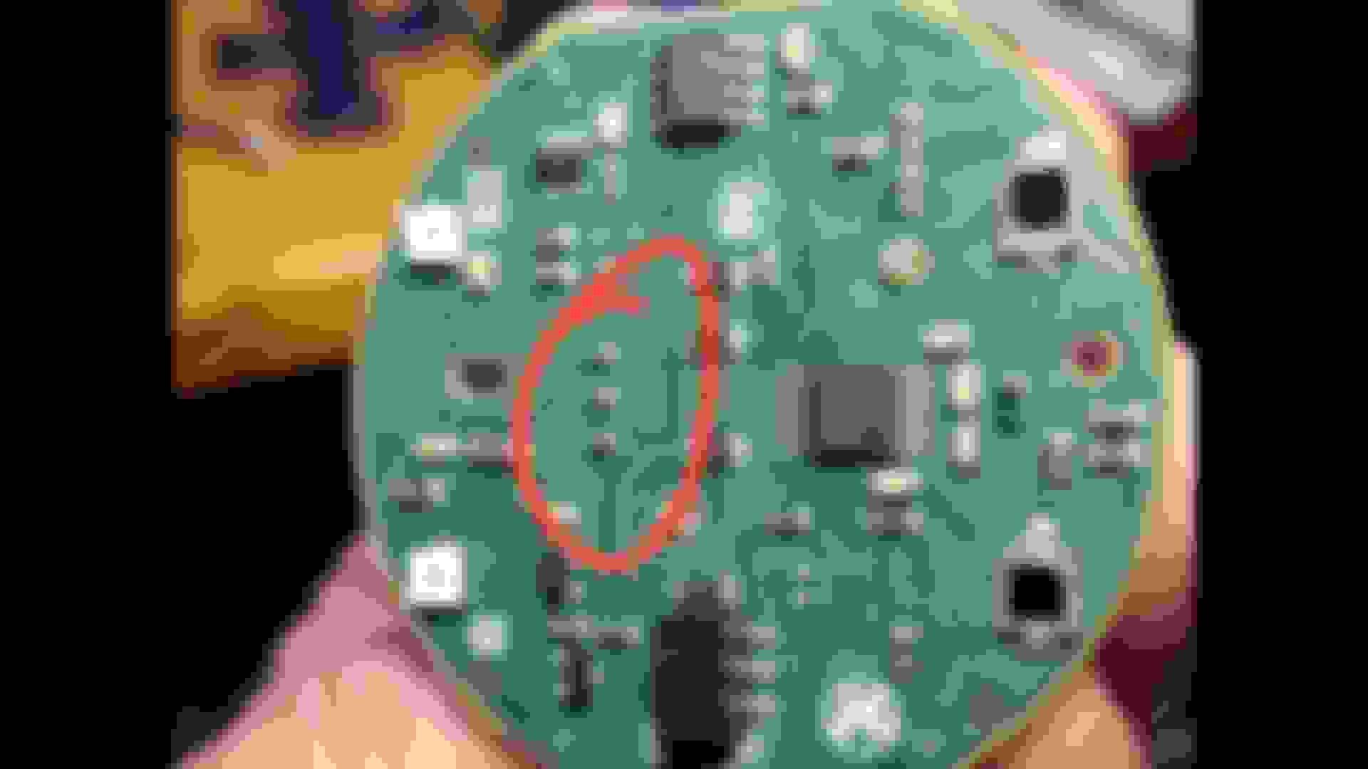
The rear SAM functionality is built around two interconnected circuit boards: the control Logic + Power interface PCB.
detached logic board: 4 connectors in use
Today I am only fixing 50% 😏 as I do not feell like screwing twice with all the hardware on the power board.
Today I am fixing the unsoldered pins knowing I will need to come back for the second half. This will happen shortly once I have found a flexible coating that can handle engine heat - The best for this application seems to be a silicone sprayed film.
(the small con. is unused... JTAG 🙂?)
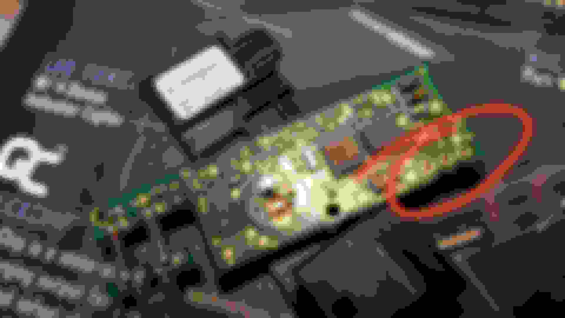
re-soldered PCB my flux removal chems cleaned up better than new
Fixing the logic board was a very straight forward cake work with my 60W Weller iron. Only 2 joints are extremely cold and will benefit from a quick hot shot of 100w iron.
I noted there was no signs of over heated pins on the logic board, as one would expect on low power controls. The heavy lifting is handled by the other circuit...
The component side stayed verboten by hot melted plastic rivets. I will need to cut them out carefully to spray coat the hidden circuit side. They are involved with holding the PCB in place!
For now I am curious to see what improvement if any, this brings to chatting with the LIN battery sensor all the way upfront.
Last edited by CaliBenzDriver; Jun 25, 2021 at 01:21 PM.
This is quite the dedication.. you're planning to keep the W212 forever? Hopefully all of your efforts lead to a long, trouble-free life of the car.
The Rear-SAM took me less time than an oil change. It's seriously simple like a flat tire.
What I've done is very easy trust me. The hard part would be fixing component level or combing a schematic for random conditions. I have done enough of that in my early days to use an ounce of prevention now. I can read a board's architecture.
Compare electronics to troubleshooting a lean LTFT on a twin-turbo V8 or rebuilding a tranny by a seasoned wizard... that's when I bow
++++++
There are many knowledgeable ppl helping around here, this is my contribution where needed.
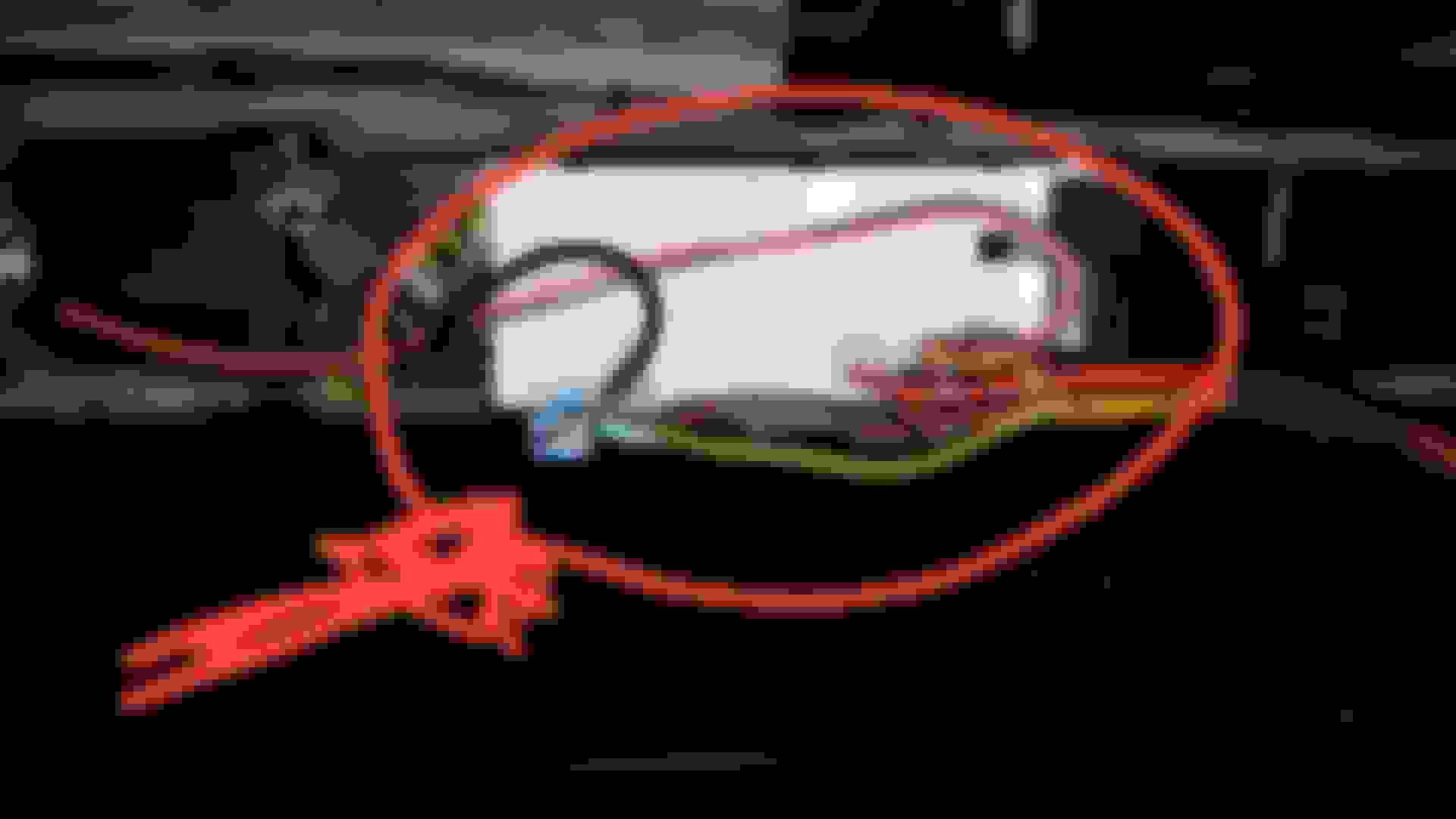
rocking F-SAM out
sit back: F-SAM T20 screws are out....
So actually it is a single piece unit by Bosch: more than what I want to chew now (need my spray coating)
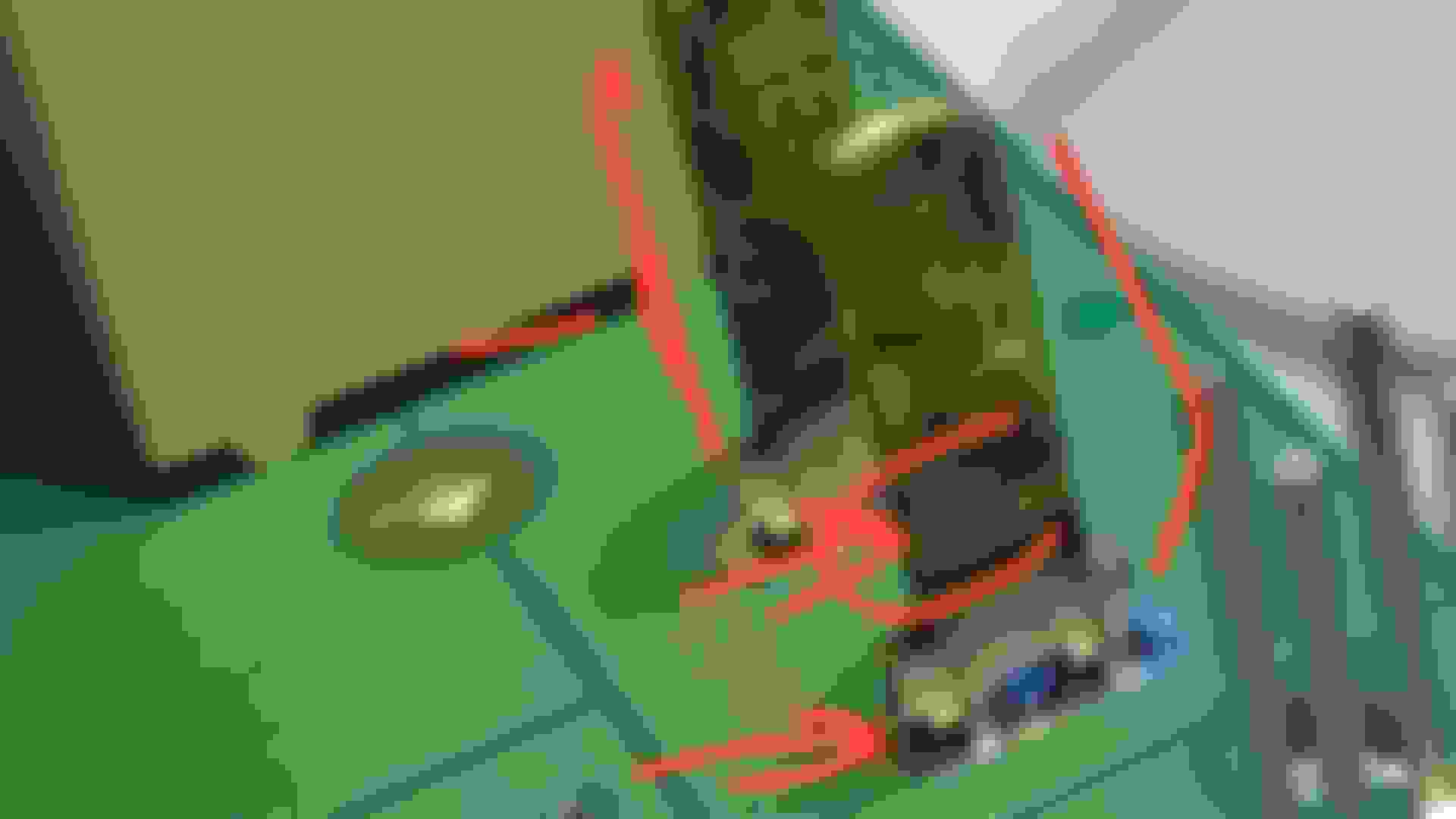
Simple but time consuming ("3Hr surgery"):
6x conn. for logic side
15x conn. for power side
8x relays
3x dozen fuses
✌️
Last edited by CaliBenzDriver; Jun 26, 2021 at 05:18 PM.
Can you remove the F-SAM without removing the wiper assy ?
I can't on my RHD.
The white box of F-SAM you did not detached it from firewall ... right ?
I am not sure if wipers can stay or need to get removed to remove F-SAM, I am going commando without any documented procedure.
Based on what I saw there are 70% chance it'll be simple. I haven't extracted it yet.
I can see the bottom of the logic board is cut at angle so you may not need to lift it straight up. Try to tilt it forward then lift harness out of white box side openings.
I am doing everything possible to limit the amount of dismentling and reassembly.. So if the white box can stay put, I won't extract it.
You may have more luck than me cracking open F-SAM to fix dropped voltage from pins
Mercedes SLR McLaren 722 S Is Extremely Rare Example Modified by McLaren
Slideshow: A one-of-one U.S.-spec Mercedes-Benz SLR McLaren Roadster became even rarer after a factory-backed transformation at McLaren's headquarters.


 ..... is that on your car Cali ?