When you click on links to various merchants on this site and make a purchase, this can result in this site earning a commission. Affiliate programs and affiliations include, but are not limited to, the eBay Partner Network.
AC service port. Which is which? Please help. Thanks
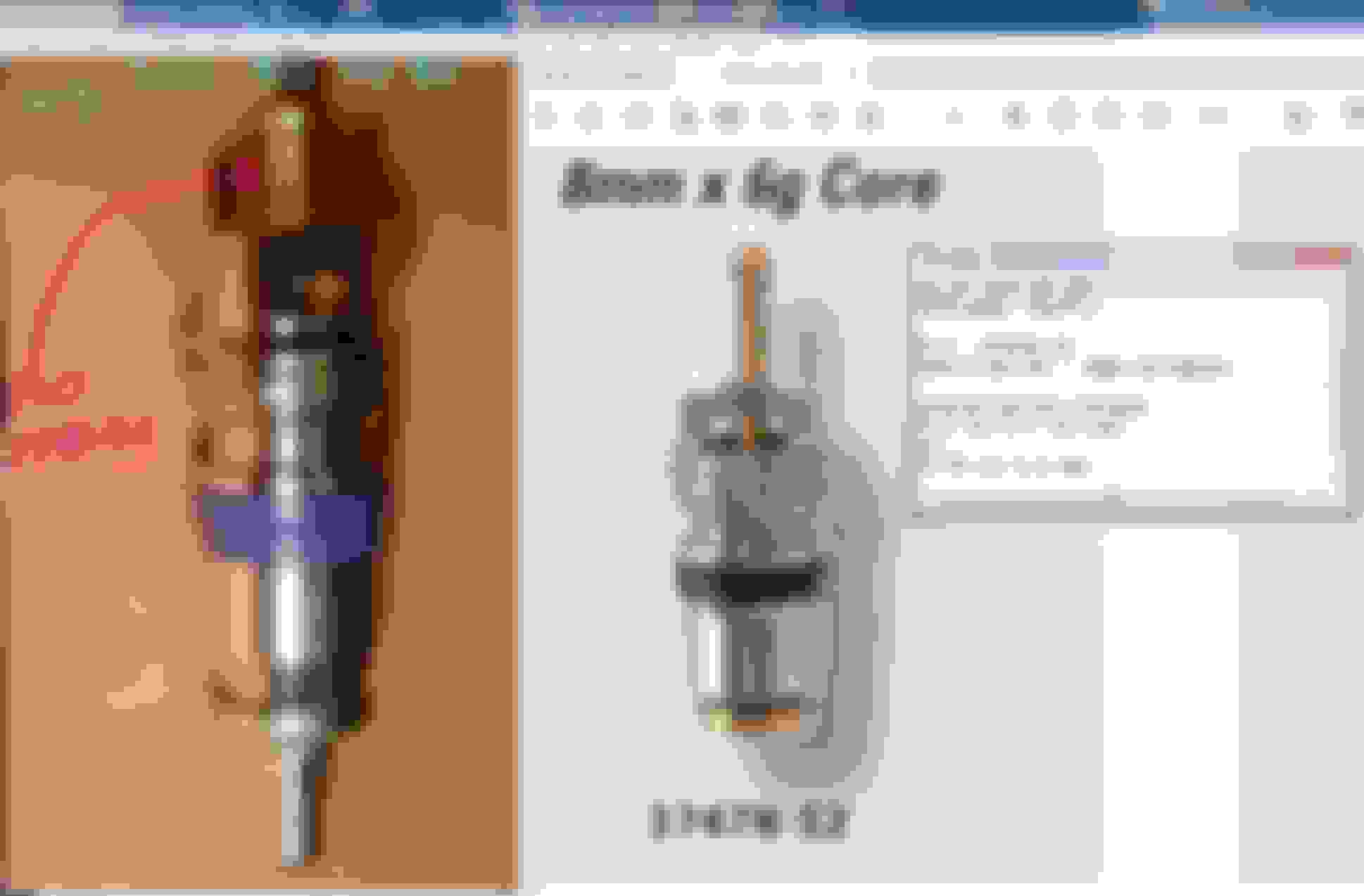
Good day all. My ac low side port has a leaking valve. Parts seller is not sure which one #380 or #150) is a low side one (his diagram attached).
Am I correct that #380 is for the low side? Any help is appreciated. Thanks.
Just to mention: (STEAL)dealer does not sell the Schrader valves (nor the control valve), it sells the hose with the port and the valve . I bought both valves in the picture (see the link), took it to a AC service place, they evacuated, I replace the valve and took it back for recharge to the EXACT amount posted in the label (each MB is different, so careful). Total cost for evacuating/recharging around here (a few weeks ago) $140+Tax, give or take. This AC service shop charges $40/pound R134a for the difference between refrigerant required and refrigerant evacuated, i.e. whatever you have in still has value.
The TXV is a smart orifice tube. It's a modern enhancement used everywhere.
The TXV is able to adjust the orifice opening based on the evap. temperature above freezing.
This provides maximum cooling and prevents icing the evaporator coil and restricting air flow.
When A/C runs on low blower, the TXV can hardly open before freezing happens. To get a good TXV throughput we need enough warming of the coil with high air flow.
In turn this allows the compressor proportional valve to command deeper piston strokes, right?
Cali, I looked at those in Amazon; however, I was not convinced it could handle the size of the valve. Some valve are deeper than others, and the diameter of the extractor must allow for all valve sizes. Even the notch at the tip of the extractor tool must be the correct size. If too narrow, need to pry it a bit out to increase it, so it locks on the Schrader valve, and able to turn.
Size differences, the W166's are definitely different. Let me check the old ones and post pictures.
The only issue with the extractors is the unknown amount of refrigerant in or lost. No way to match by weight
The valves for the W166 being available stand-alone is news to me unless the salesperson at the dealer was playing dumb. The part must be ordered, the whole hose with port and valve: thank you, not a chance. Removing hoses is a recipe for more parts: drier as a start, and who knows what else. The valve is quick, had it ready with another tool, and my brother assisted ( scalpel, gauze, ), then proper vacuum.
The one @konigstiger listed is the most right; 2012 W166's are the one in the middle and most left.
Update: I checked a parts page, and definitely the W166's valves are not available standalone , Diagram for W166, not W212
These are the old valves for the W166. Wonder how they make those decisions during the design. Different designs within close requirements drive costs UP.
Thanks all. Having searched for a whole day, I managed to make sure that the valve element in low side port (for W212) should look like this. For sharing.......
Interesting thread, thank you My W212.
It got me thinking preventive and would also buy the valve core ahead and the protection cap too, because that is a secondary seal.
I keep reading commercial HVAC boys would always point out that the schrader valve core can have minor leak eventually and the cap with seal will assist a great deal.
I then took photo to see if indeed there is a seal on our plastic caps. Yes there is and the same purple-ish color like how the Pelican Parts shows the valve core also uses that purple seal.
I was always wondering why it is called Schrader valve ?
It is the founder name and the company is still alive today. https://schrader-pacific.com/about-us/
I guess its like Hoover is a vacuum cleaner nickname.
I remembered my Dad in the 80s when he wants to get document photocopied, he will say go and Xerox it
I been wondering about valve cores, there are for fuels, tires and the HVAC.
I think if we are not careful if we get a tire quality one, it will be a disaster for HVAC as the sizing seems the same : https://schrader-pacific.com/wp-cont...Valve-Core.pdf
The same for the fuel test port, same valve core size.
All 3 different application have different seals material and pressure + temperature rating for sure.
Wow wow...we must buy genuine Mercedes one or genuine Schrader one equal to or higher spec one..........to be risk free as these small valve core seal we can not define by color or touch.
Anyway I was playing with it and can provide some worthy information :
Size wise
Yes, you must buy from MB as even Grand Daddy Schrader Pacific does not make MB type. Their so callled 8mm european valve core is below :
MB type compared to the standard tire or general purpose valve core
The cap seal is a round circular like an o-ring, I thought it was a flat-circular one
I got a hold of a JRA type core, for size comparison
JRA size
Now, do not buy item A tool below, which if suitable can remove valve core while it is under r134a pressure, it can't work with the MB valve core but will work with JRA valve core.
The valve core removal tool uses the JRA valve core spring's as interference fit as grabbing mechanism to lift up and out the valve core.
MB valve core is so fat at the top dot, it can't even enter the removal tool center bore. and MB one has no top side spring anyway.
Tool B can work with MB valve core, tool's fat side.
Very interesting findings on the MB A/C specialty valve cores.
Fat/Skinny:
We know each side uses a different core size, right. Have you tried to see if the FAT valve head fits your RED tool ?
Both LP and HP r134a port of W212 HVAC uses same valve core size and Part Number.
The tool B will not be able to be used in tool kit A1 or tool kit A2 or tool kit C.
The Tool A ( A1 and A2 ) its bore size inside chamber 1, where the valve core will be moving out from ..........is too small for our W212 8mm class valve core, even let say I can modify
the push-pull shaft with the valve core gripper end to work on our W212 valve core.
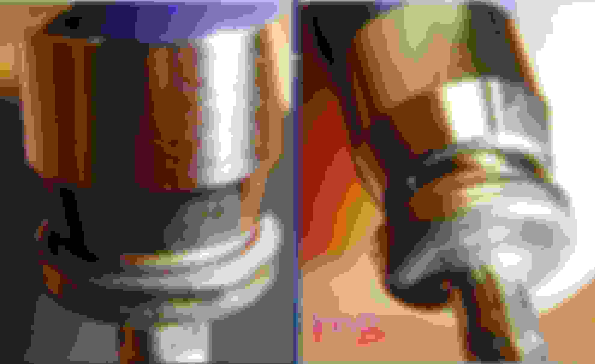
I forgot to show how our W212 valve core push-to-open seal looks like. Here you go :
The sealing surface is so thin for its contact surface between the metal orifice to the purple color polymer seal, any dirt will make a minor leak for sure.
==============================
Something is bothering me, because I am not able to find the design parameters of the r134a quick coupler set forth by SAE.
The maximum allowed push depth or push travel of the push rod, from a known reference zero.
My main worry is the allowable push depth of the push-rod inside the quick coupler, If it is too much or to deep, the valve core will be damaged.
The SAE will surely have design guideline on this matter and will prevent from the push rod pushing too much.
I am worried if an unknown China brand coupler not adhering to the this standard, 1 mm extra push depth can damage the valve core.
I now only have Yellow Jacket ( US most trusted brand for coupler ) coupler and red HP side only, blue LP side is China one although I bought the best one in Ali-Express.
I bought this Yellow Jacket HP coupler like middle of last year, long before I would think I will do HVAC on my own this end of April if I can.
Initially I wanted to use that HP coupler only to read HP side vacuum micron reading if and when I use HVAC workshop with 3R machine.
For now, I can't measure reliably the push rod depth, my caliper sunk a bit as shown. I need to make a flat plate first or a washer big enough to make as the flat surface.
I have faith in Yellow Jacket dimensional tolerance but I do want to learn of the push rod maximum depth for learning and future caution.
There are 3 other variables which will effect the reference zero position.
AA. The maximum seated depth of the valve core in regard to different brand or car using different valve core.
BB. The maximum height the valve core push stem and its allowable travel.
CC. The position of the ball locking channel/groove of the coupler, assuming the r134a mating port in all cars are all 0.1mm tolerance to SAE spec.
I worry of this coupler is because it is a spin type adjustment of push rod depth using machined thread. It give no feel to our fingers unless obstruction is hard/strong and if Uncle Murphy doesn't like you,
this could be the reason valve core may develop minor leak when one "messed" around with it using a bad quality coupler which has extra push rod depth because of poor dimensional tolerance in its manufacturing.
If the coupler push rod is not able to push deep enough to SAE standard, it won't be so bad except slow vacuuming.
Even using Yellow Jacket, I think I will do max 4mm push rod depth to be safe, if I can actually measure it. But I have to find where the reference ZERO is first...
Need to count maximum how many millimeter push rod depth I get, per 360 degrees spin of coupler spinning knob.
At the red-HP side at the car, the valve core mini shoulder to top of port is 10 mm, +- 0.1mm measurement error on my part. 1 got 10.07mm
Too bad I do not have the exact aluminum port as used on the car, I only have my brass "practice port", which its dimensions may not be 100% the same as the one on the car be its outside dimension,
or how the valve core is seated etc etc.
=================
Comparing Yellow Jacket to a good China one. Up close with naked eye, the Yellow Jacket is indeed a well made unit, good finish and yada yada.
Notice the locking ***** position or depth, is different between the two brands. The locking ball position will effect where the ZERO reference point would be, if all other dimensions are
the same 100% between this two brands.
I shall update when I am able to find the reference ZERO level of the valve core small stem as installed and maximum travel of the Yellow Jacket push rod towards/from the reference ZERO.
For now I use my ear to hear pressure or see the gauge reading and only give 1 extra 360 degree turn on the spinner knob of the quick coupler as soon as the valve core started to open.
I recalled when I did the test above, the blue-LP one from China can spin its knob more to maximum travel after the valve core already open up a bit, compared to the red-HP Yellow Jacket which has less.
However, using the China test port HP size one , with the JRA valve core built-in, the red-HP China coupler one actually push almost 0.75mm less than Yellow Jacket red-HP.
I need to get the Yellow Jacket blue-LP coupler soon.
Both LP and HP r134a port of W212 HVAC uses same valve core size and Part Number.
The tool B will not be able to be used in tool kit A1 or tool kit A2 or tool kit C.
The Tool A ( A1 and A2 ) its bore size inside chamber 1, where the valve core will be moving out from ..........is too small for our W212 8mm class valve core, even let say I can modify
the push-pull shaft with the valve core gripper end to work on our W212 valve core.
I forgot to show how our W212 valve core push-to-open seal looks like. Here you go :
The sealing surface is so thin for its contact surface between the metal orifice to the purple color polymer seal, any dirt will make a minor leak for sure.
==============================
Something is bothering me, because I am not able to find the design parameters of the r134a quick coupler set forth by SAE.
The maximum allowed push depth or push travel of the push rod, from a known reference zero.
My main worry is the allowable push depth of the push-rod inside the quick coupler, If it is too much or to deep, the valve core will be damaged.
The SAE will surely have design guideline on this matter and will prevent from the push rod pushing too much.
I am worried if an unknown China brand coupler not adhering to the this standard, 1 mm extra push depth can damage the valve core.
I now only have Yellow Jacket ( US most trusted brand for coupler ) coupler and red HP side only, blue LP side is China one although I bought the best one in Ali-Express.
I bought this Yellow Jacket HP coupler like middle of last year, long before I would think I will do HVAC on my own this end of April if I can.
Initially I wanted to use that HP coupler only to read HP side vacuum micron reading if and when I use HVAC workshop with 3R machine.
For now, I can't measure reliably the push rod depth, my caliper sunk a bit as shown. I need to make a flat plate first or a washer big enough to make as the flat surface.
I have faith in Yellow Jacket dimensional tolerance but I do want to learn of the push rod maximum depth for learning and future caution.
There are 3 other variables which will effect the reference zero position.
AA. The maximum seated depth of the valve core in regard to different brand or car using different valve core.
BB. The maximum height the valve core push stem and its allowable travel.
CC. The position of the ball locking channel/groove of the coupler, assuming the r134a mating port in all cars are all 0.1mm tolerance to SAE spec.
I worry of this coupler is because it is a spin type adjustment of push rod depth using machined thread. It give no feel to our fingers unless obstruction is hard/strong and if Uncle Murphy doesn't like you,
this could be the reason valve core may develop minor leak when one "messed" around with it using a bad quality coupler which has extra push rod depth because of poor dimensional tolerance in its manufacturing.
If the coupler push rod is not able to push deep enough to SAE standard, it won't be so bad except slow vacuuming.
Even using Yellow Jacket, I think I will do max 4mm push rod depth to be safe, if I can actually measure it. But I have to find where the reference ZERO is first...
Need to count maximum how many millimeter push rod depth I get, per 360 degrees spin of coupler spinning knob.
At the red-HP side at the car, the valve core mini shoulder to top of port is 10 mm, +- 0.1mm measurement error on my part. 1 got 10.07mm
Too bad I do not have the exact aluminum port as used on the car, I only have my brass "practice port", which its dimensions may not be 100% the same as the one on the car be its outside dimension,
or how the valve core is seated etc etc.
=================
Comparing Yellow Jacket to a good China one. Up close with naked eye, the Yellow Jacket is indeed a well made unit, good finish and yada yada.
Notice the locking ***** position or depth, is different between the two brands. The locking ball position will effect where the ZERO reference point would be, if all other dimensions are
the same 100% between this two brands.
I shall update when I am able to find the reference ZERO level of the valve core small stem as installed and maximum travel of the Yellow Jacket push rod towards/from the reference ZERO.
For now I use my ear to hear pressure or see the gauge reading and only give 1 extra 360 degree turn on the spinner knob of the quick coupler as soon as the valve core started to open.
I recalled when I did the test above, the blue-LP one from China can spin its knob more to maximum travel after the valve core already open up a bit, compared to the red-HP Yellow Jacket which has less.
However, using the China test port HP size one , with the JRA valve core built-in, the red-HP China coupler one actually push almost 0.75mm less than Yellow Jacket red-HP.
I need to get the Yellow Jacket blue-LP coupler soon.
Your study is very interesting and particulally useful to me because I am thinking how to replace the leaky valve core of low side port without refrigerant recharge. Too bad that I have ordered the blue one (valve core removal tool) before reading your article.
Yes, that tool can't help in replacing MB valve core, which is fatter and longer than other ordinary core. Now, I may need to empty the ac system and replace the valve core by using the basic removal tool.
I assume you want to keep your car for a long time.
My suggestion to you is, go to a proper professional hvac workshop where the machine is a 3R type ( Recovery/recycle/recharge (RRR) or 3R ) ... and has refrigerant analyzer, to do that simple valve core replacement and
at the same time bring the charge back to proper grams/weight suitable for your W212 model. Mine is 590 grams of r134a.
And then you request that the vacuum process to be 40 minutes long at least and make sure their hoses are evacuated* before the charging begin ( *some lazy tech may manual over-ride this function and not evacuate the hose ).
Attached refrigerant charge level document
Thanks for the advice. Yes sure, I plan to keep my car for a long time because i have invested lots of time (mostly DIYs) in it so that it runs better than when I brought it 3 years ago..... : )
About the recharge, I used this kind of machine to do 3R last time a year ago. But the refrigerant has almost gone due to a leaking low side port. I remember that only 10 minutes or so of vacuum time is set in the machine so that I am not sure it could run 40 minutes vacuum. Will ask the shop when doing the 3R again....
Thanks to you , I intend to replace my non-leaking valve core probably April/May 2023. It will leak someday and I want to prevent that, afterall the car is 9 years old by registration this June but by assembly date I think
it is end of 2013 as per Data Card, so it is actually 7 months older.
The vacuum setting can be adjusted manually for duration of work The problem with 10 minutes or even 20 minutes is that the hose they use is small, usually 1/4" or at best 5/16" if TEXA brand 3R machine and them hoses are like 2 meters long and
the vacuum process gets very bad & slow using those small hoses even when the vacuum pump in the machine is brand new and super healthy and 8CFM capacity.
Hence I recommend 40 minutes, and hope for the best.
Its about time is money and workshop tends to cut short vacuuming process.
That Launch Value-300 3R machine does not have built in refrigerant analyzer, do they have stand alone analyzer ? This is this to guarantee you do not get contaminated refrigerant from previous cars using that machine.
I forgot to mention this :
Yesterday I was messing around with my Wife Toyota Corolla Cross HVAC. I need to experiment first on NOT MY CAR , before I mess with my E400.
Engine bay is so huge for an engine so small 1.8L, so easy to see everything.
What I want to inform you all is, I think there is a way to detect minor leak at the valve core, when and if your cap is still good and healthy.
This is a Nov 2020 car.
When I un-screw the HP port cap, I can feel the pressure pop, which I did not feel on my E400 HP cap or I was not paying attention
That means since Nov 2020 to 22nd March 2023 there has been pressure build up on HP port. Its never been opened since new. I do not feel any pop on the LP port.
I do not know if this is the acceptable leak rate of a valve core ( all valve core will leak some super small small percentage for sure ) or is it out of the norm ?
LP & HP port will see pressure only at 100 psi-g for my ambient temperature when engine off and cold and when heat soaked after a trip, to say engine bay being 80C,
both LP and HP may see up to 367 psi-gauge being the saturated pressure/temperature of r134a at 80C. Probably LP port will see less pressure as the evap is inside the cabin and not engine bay so LP section is not all at 80C.
LP will be under 50 psi-g when AC compressor is running and HP port when AC running may see up to 210 psi-g on this Toyota during my test.
I think if us owners is willing to check this possible extra pressure once per 6 months by feeling the protection cap slowly and carefully when un-screwing,
it may reveal early minor leak from the valve core if there is any.
Last edited by S-Prihadi; Mar 23, 2023 at 03:01 PM.
Interesting. The M276 has 3 ground paths, correct? Starter, plus 1 on each bank next to the injection rails, correct?
Juan, Surya will know that for sure...
I think M276 only has a single chassis GND strap located under the car exposed to under carriage projections.
Having more than one engine/chassis GND strap is a requirement if you ask me.
It is heavily used by starter and by alternator. So that means every load feeds through engine strap... be it single or double strap.
The GND screws on/near valve covers are for local loads: injectors, coils and to reference some ECU circuits. No heavy power load there, just super noisy with the fancy piezo injectors giving multiple shots per compression.
🙂
Last edited by CaliBenzDriver; Mar 23, 2023 at 03:58 PM.
Interesting. The M276 has 3 ground paths, correct? Starter, plus 1 on each bank next to the injection rails, correct?
Well engine wise , my M276 has only 1 main ground wire, the one from lower chassis of car to the engine starter.
All other grounds are equipment ground taken either from engine block or left or right monocoque chassis of engine bay.
My M276 3.0 TT for its ECM get ground from Bank 1 ( left ) cylinder head.
So in theory this Toyota has better ground for components on the engine itself because the 2 ground cables indicated by Cali is to provide more direct ground to cylinder head for the ignition and
I believe the actual ground source could either be ECM or some chassis ground, where in my M276 the cylinder head is the ground for ECM.
I have beefed up my E400 grounds to engine and to cylinder heads
Cali,
Damn u got eagle eyes my man
I never bother to learn anything on this car, except I did the CVT tranny oil change at 5,400KM as running-in oil change.
It will be sold for sure by 5th year. Me wife doesn't like car older than 5 years.
We drink the same coolaid... we understand how troubles are engineered and know how to deal with some of Mercedes games.
> Basic upgrade :
What location do you think is best to double up the chassis GND path ?
Near opposite of existing strap ie. left hand top side ?
> MB Power GND Setup:
-- The way Mercedes likes to strap ECU to vibrating hot engine either on top or over exhaust pipes make it directly referenced to engine more so than chassis.
-- The way Japanese like is to be referenced to battery side ahead of any drop. Cost nothing and simply is a smarter choice.
Back to our M276...
Starter battery is referenced to chassis better than engine.
In between Batt and ECU we have the single chassis to engine strap.
A perfect opportunity for glitching ECU with low battery and oxidized painted GND.
We like moding things better... add the missing GND strap!
Arigato
Last edited by CaliBenzDriver; Mar 23, 2023 at 04:47 PM.
We drink the same coolaid... we understand how troubles are engineered and know how to deal with some of Mercedes games.
> Basic upgrade :
What location do you think is best to double up the chassis GND path ?
Near opposite of existing strap ie. left hand top side ?
> MB Power GND Setup:
-- The way Mercedes likes to strap ECU to vibrating hot engine either on top or over exhaust pipes make it directly referenced to engine more so than chassis.
-- The way Japanese like is to be referenced to battery side ahead of any drop. Cost nothing and simply is a smarter choice.
Back to our M276...
Starter battery is referenced to chassis better than engine.
In between Batt and ECU we have the single chassis to engine strap.
A perfect opportunity for glitching ECU with low battery and oxidized painted GND.
We like moding things better... add the missing GND strap!
Arigato
I wonder why W212 has only 1 ground strap from body to the engine. The W166 has that one plus some ground from the AC compressor to the body (which W212 does not). On the ECU locations, MB is slow-cooking components for repetitive replacements
I wonder why W212 has only 1 ground strap from body to the engine.
The W166 has that one plus some ground from the AC compressor to the body (which W212 does not).
On the ECU locations, MB is slow-cooking components for repetitive replacements
Slow cooked capacitors are my favorites... you can't see electrolytes leak but the uF value is in the dumps: awsome glitching opportunities when filtering is all gone. 🤞
That W166 sounds like a good example to help us rework W212 with missing strap. (Do you have a pic of this beauty?)
The best location for a flexible breaded strap is where the engine moves around the least.. presumably near the engine mounts like Japanese do.
The engine-tranny vibrations are another good reason to double up the main strap. Mechanically it can only endure motions for so long - same reason why cargo door harness always break apart!
>>> Maybe we should jump out of Surya's A/C thread
+++ w166 strap +++
The next thing you know is we're gona want to use the same part number
Last edited by CaliBenzDriver; Mar 23, 2023 at 06:05 PM.
Reason: W166 part#
Mercedes SLR McLaren 722 S Is Extremely Rare Example Modified by McLaren
Slideshow: A one-of-one U.S.-spec Mercedes-Benz SLR McLaren Roadster became even rarer after a factory-backed transformation at McLaren's headquarters.


 . I bought both valves in the picture (see the link), took it to a AC service place, they evacuated, I replace the valve and took it back for recharge to the EXACT amount posted in the label (each MB is different, so careful). Total cost for evacuating/recharging around here (a few weeks ago) $140+Tax, give or take. This AC service shop charges $40/pound R134a for the difference between refrigerant required and refrigerant evacuated, i.e. whatever you have in still has value.


 Cali, I looked at those in Amazon; however, I was not convinced it could handle the size of the valve. Some valve are deeper than others, and the diameter of the extractor must allow for all valve sizes. Even the notch at the tip of the extractor tool must be the correct size. If too narrow, need to pry it a bit out to increase it, so it locks on the Schrader valve, and able to turn.
 ), then proper vacuum.


 and the company is still alive today. https://schrader-pacific.com/about-us/


 or a washer big enough to make as the flat surface.