When you click on links to various merchants on this site and make a purchase, this can result in this site earning a commission. Affiliate programs and affiliations include, but are not limited to, the eBay Partner Network.
The new Compression tester arrived, has an extension to drop in to the deep spark plug holes. I was thinking perfect so while I have the manifold off to test the coil and injector wire harness I will check the compression just to verify. #1 tests to 95 PSI, panic steps in so I test #2, tests to 95 PSI. I think my tool is not working proper so I grab another gauge and attach it to the new tool, it tests to 95 PSI. Now I know #2 has never had a misfire and no way it can do that with only 95 PSI. So I start thinking about how this is happening. Look at the new tool extension. It is aluminum, about 10" long, maybe only 9". But the bore on this is larger than 1/4". That alone is a lot of area. This is a small bore engine with a small head chamber to have 12.5:1 compression so any area added will reduce the compression. Piston deck height, the distance from the piston head to the cylinder head is always measured and checked on overhauls to make sure we don't gain or lose compression so I started thinking about how much is lost with this new extension tube? I have a 20" hose that fits my compression tester and that hose was the only thing I had available to connect the tube to my compression guage. So now I have a large tube and a long hose connected to my guage adding a lot of area to compress in my cylinder test. My hose has the right threads to screw in to the Mercedes spark plug hole but the hose has a connector that is too large to go down into the spark plug hole. I ground the connector down till it could go down in the plug hole so now I could hook up my guage with just the hose and not the extension. New Test Compression jumped to 140 on both #1 and #2. A 45 pound increase from removing the aluminum extension tube which was sold to fix my connection issue. I have zero doubt that if I could connect without my 20" extension hose compression is certainly fine. Somewhere around 170 PSI per cylinder. The good news is #1 and #2 are identical for pressure. The new tube is not a total waste because it does help me connect when I do a Leak Down Test which uses 100 PSI of air pressure to look at cylinder health. Compression tests are quick and good but a Leak Down test gives you more information, showing if your leak is Intake Valve or Exhaust Valve, Rings or Head Gasket. It is a more valuable test for engine health. Many do not have or have not used a Leak Down tester but it is a valuable test tool.
Someone mentioned a possible broken valve spring? That might cause an issue like this if it could close the valve at stop but allow it to flutter open when running. #1 valve springs were right there in front of me for hours as I worked on the cams, I did not notice a broken spring but in the past I have seen some broken springs that were hard to see when assembled so Possible I guess, but I hope not, AND I have zero noise from the running valve train other than the fuel injectors normal noise. Wish I had checked with the valve cover off. I did look inside the intake chamber to see both valves are opening and closing as one at least to the naked eye.
So far the Grounds on coils #1 and #2 test .01 OHMs from the coil to the ground on the valve cover. .01 or .00 OHMs of resistance which is what I get if I touch my two multi meter probes together so I read, no resistance and the ground circuit is good.
The other 3 coil wires are harder to test. Two coil wires connect directly to the other 2 coils on bank 1, One wire, #4 I think wires directly to the ECM. I still have not figured out what pin at the ECM this is. I want to verify the Coils wiring and hope that finds my problem but without the ability to test for waveforms while running I do not see how I can find the injector issue and Yes, I am thinking it may be inside the ECM but would like to prove it before buying a new ECM and get it programed.
I don't know how to load the wires to make sure they function under loads, maybe when the WIS copy comes in it will show normal loads for these Coil Wires and Injector wires and suggest how to test them.
Simple load test: review: probably beyond basic for some of you but I am not an electrical guy. Jobs like this Mercedes wire issue are not what I normally do. Lots to learn.
AA. COP WIRES LOAD TEST at Pin #3 and #1. WILL TEST COP 1, 2 and 3 only.
No need to disconnect connectors of ECM....yet.
Ignition Key OFF, Engine OFF. If car is push button start, remove the push button and use traditional key, easier and safer.
Remove fuse #23 at Front SAM. Use your battery maintainer to maintain battery voltage.
COP number 1 and 2 and 3, their pins #3 and pin #1 get the same wire colors.
Pins to test are #3 with wire color red-green of 1.5mm size and #1 with wire color brown-white also 1.5mm. Make sure wire color is correct and also pin number.
Pin #3 is Positive coming from Z7/38z1 splice <<< X26 conector pin #5 <<< from Fuse #23 at Front SAM.
Pin #1 is negative, coming from Z6/z1 splice <<<Z6/z2 splice <<< x26 connector pin #9<<<from grounding stud W16/5
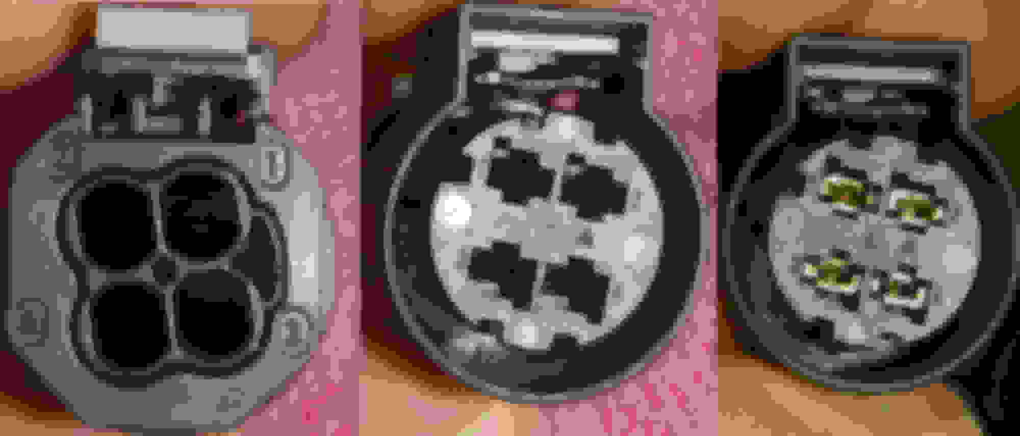
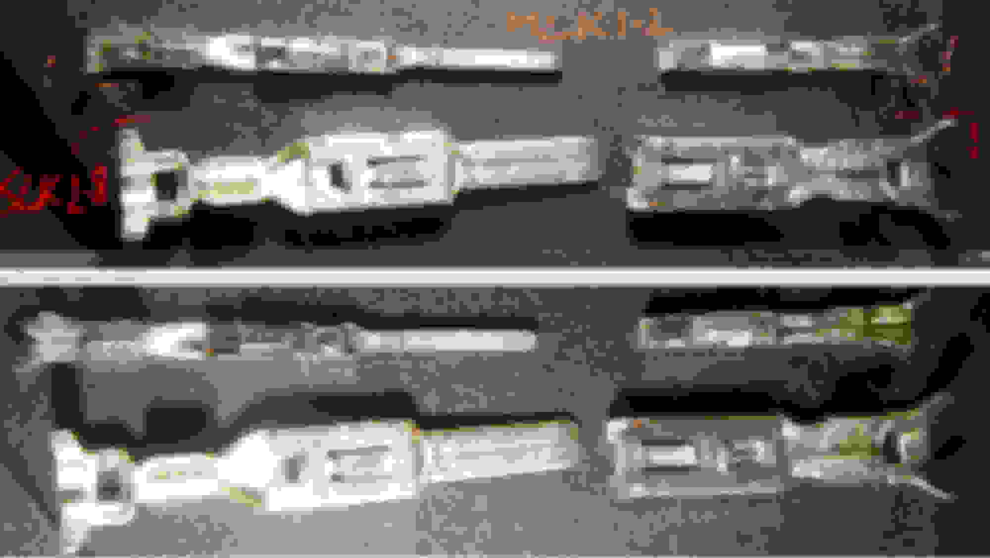
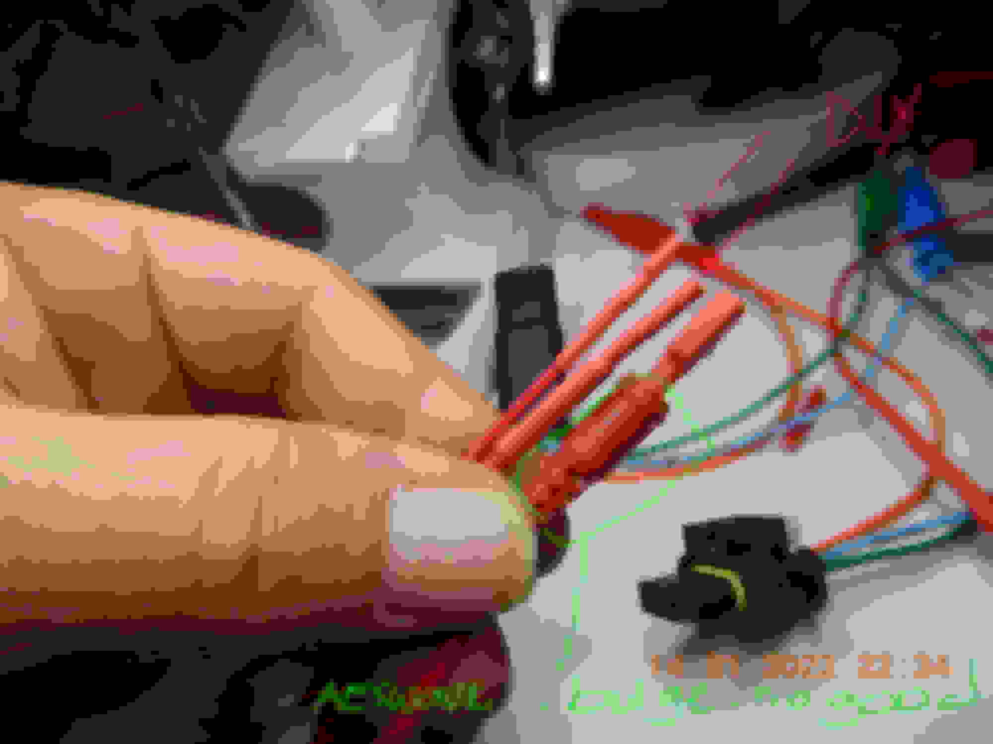
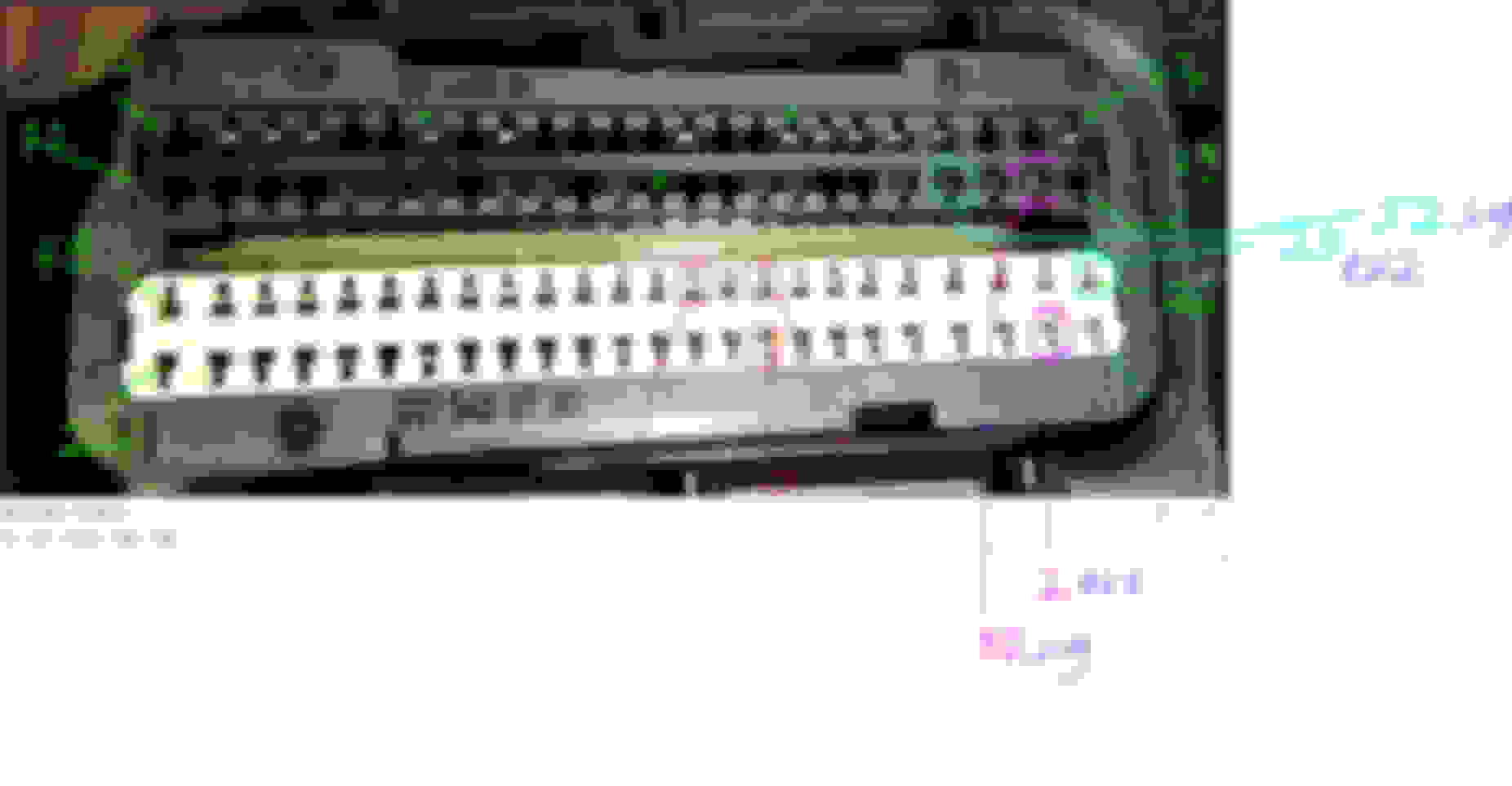
Disconnect the connector to COP, this is an SLK 2.8 female terminal meaning 2.8mm wide width shown below.
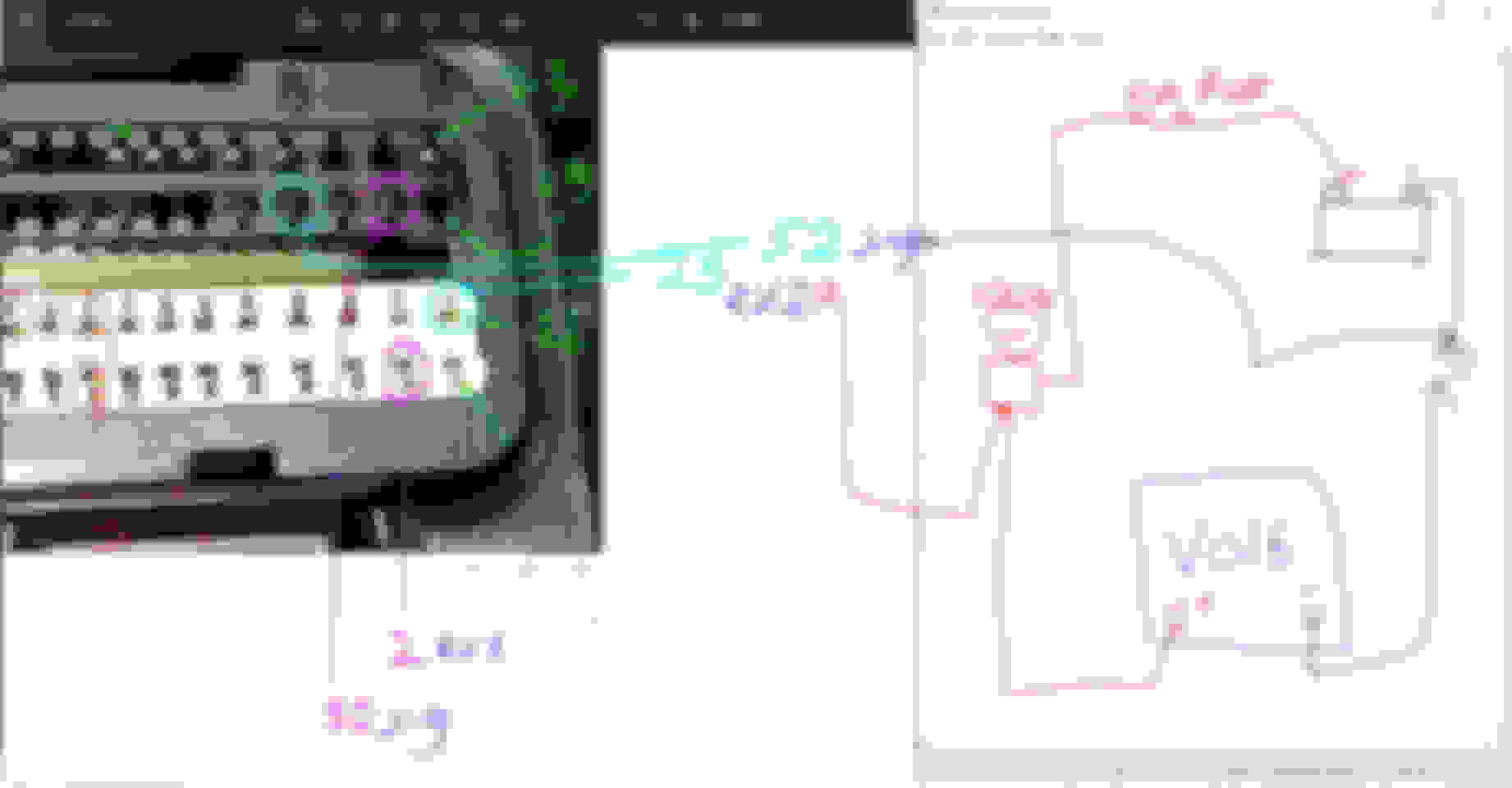
Get a 100 watt bulb ( better if total bulb is 150 watt ), as a load to replace COP.
In parallel with the 100 watt bulb, measure voltage too for the bulb.
Get a 100 watt bulb ( better if total bulb is 150 watt ), as a load to replace COP.
In parallel with the 100 watt bulb, measure voltage too for the bulb.
The male terminal you will be using, should not be too thick to "force-open" up the SLK 2.8 female terminal, otherwise you will create bad contact for the said COP.
This is the male terminal you need, if you want to get one with accurate dimension : https://www.bmotorsports.com/shop/pr...oducts_id/4197
If you do buy that SLK 2.8 male terminal from that shop ( also buy the MLK 1.2 male terminal ), please cover its exposed metal body with shrink tube
as to not cause a short circuit.
When COP 1 has been wired safely to the 100watt bulb and also the DMM/Voltmeter , only then you may re-install fuse #23 at Front SAM.
Now you turn "Ignition On-Engine OFF" or KOEO (Key On Engine Off ).
Ignition ON is when the dash instruments lights all lights up in ready to crank mode, but do not start/crank the engine please.
In KOEO mode, fuse #23 via assigned relay will be sending power to Pin #3 ( positive ), where as Pin #1 being negative is always connected to W16/5 ground stud. The 100-150W light will turn ON and see the voltage reading and note it down. If you have a 2nd voltmeter, it is to be reading battery voltage at the battery post.
Now, start pinching wire harness, hoping we you can shake-shake the positive supply Z7/38z1 splice and the negative supply Z6/z1 splice and Z6/z2 splice.
Find W16/5 ground connection and give it a shake too. Since all other 5 cylinders COP are good, if indeed there is an intermittent connection at the splice,
it would be at Z7/38z1 splice and Z6/z1 splice only and not Z6/z2 splice or W16/5 ground connection.
When you are done testing COP 1 , 2 and 3. See voltage drop comparisons between 3 COP wires.
Your battery maintainer must always be ON, otherwise we loose voltage from battery drain as in KOEO mode, our M276 will consume at least 15 amps of power.
When you are switching test between COPs with that SLK 2.8 male terminal, please always ignition key off and remove key from slot if necessary and remove fuse #23, only re-install fuse #23 when all probing connections are good at the COP.
Zs splices look like below :
Mercedes crimp a few wires, solder them and then glue them.,,Viola, SPLICE it is then.
=============== END OF TEST FOR PIN 3 and PIN 1 of COP =====================
BB. TEST OF PIN #2 of COP
While this extra ground is only for electric noise control, we still need to test it as noise can interfere with signals.
No need to disconnect connectors of ECM.
No need to use ignition key, keep it in OFF state. Keep using the battery maintainer.
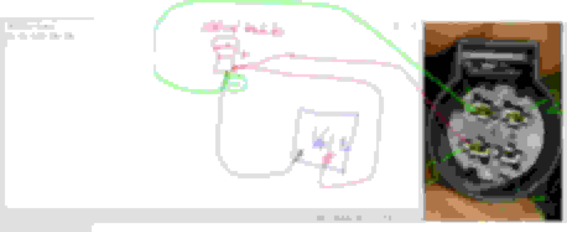
My drawing is so ugly...ha ha ha.
Do this test for COP 1, 2 and 3 at their pin #2. All 3 get same wire color, BROWN at 1mm size.
Here we are testing pin #2 which is negative and is coming from Z2/1 splice <<< W11 ground stud.
=============== END OF TEST FOR PIN 2 of COP =====================
CC. TEST OF PIN #4 of COP
This one is the tricky one because the test requires you to find its pin at the ECM harness side.
COP connector Pin #4 is a low level trigger signal for COP to fire its internal driver. I believe it is only 5 volts and amperage wise is very small,
probably less than 100 milliamps. If bulb is 150 watts total, reduce it down to maximum 50 watts.
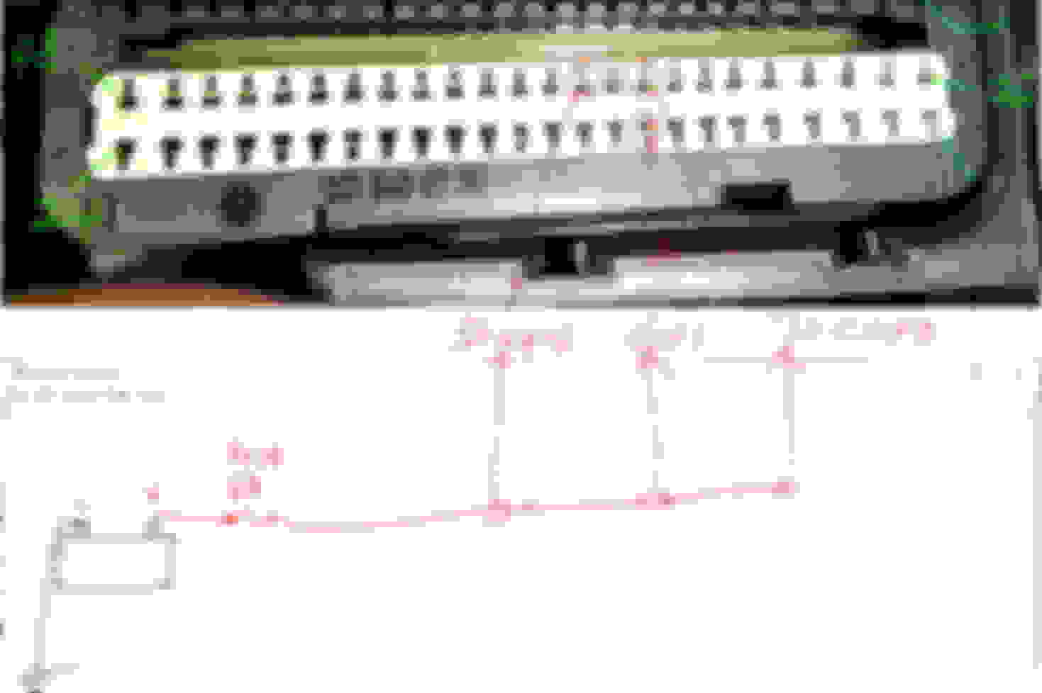
Since I am not home, I will use M271 ECM connector as example. The basic connector design is the same.
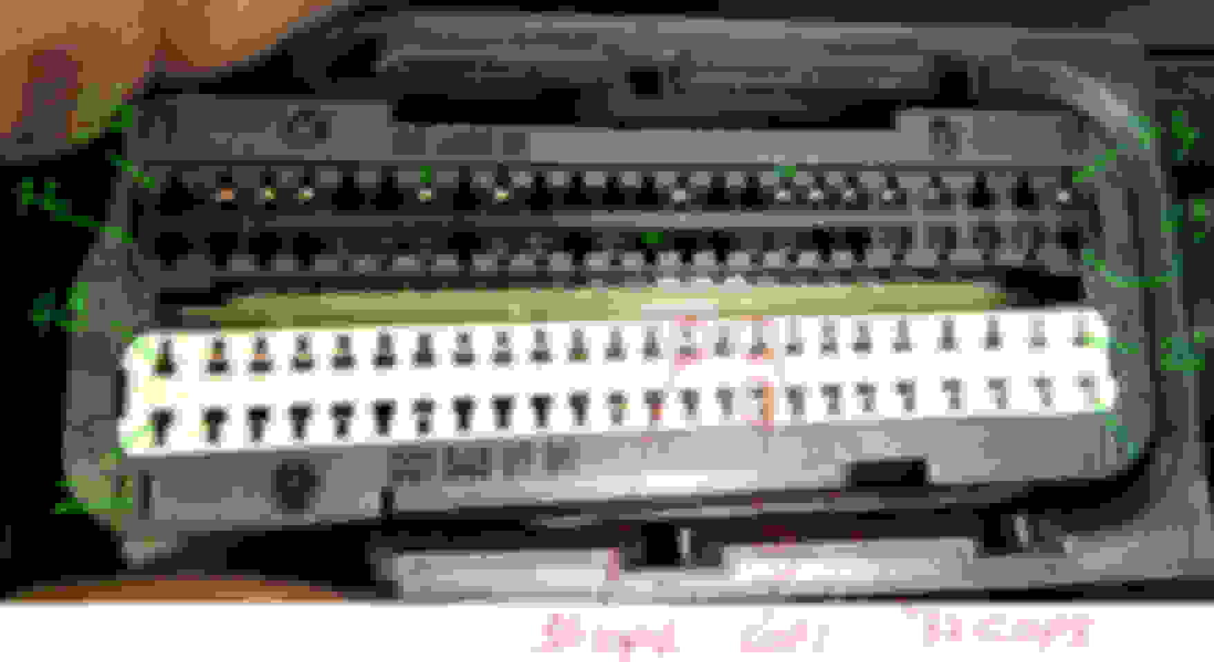
ECM get 2 connectors, 56 pins and 96 pins one, or 1 long and 1 short.
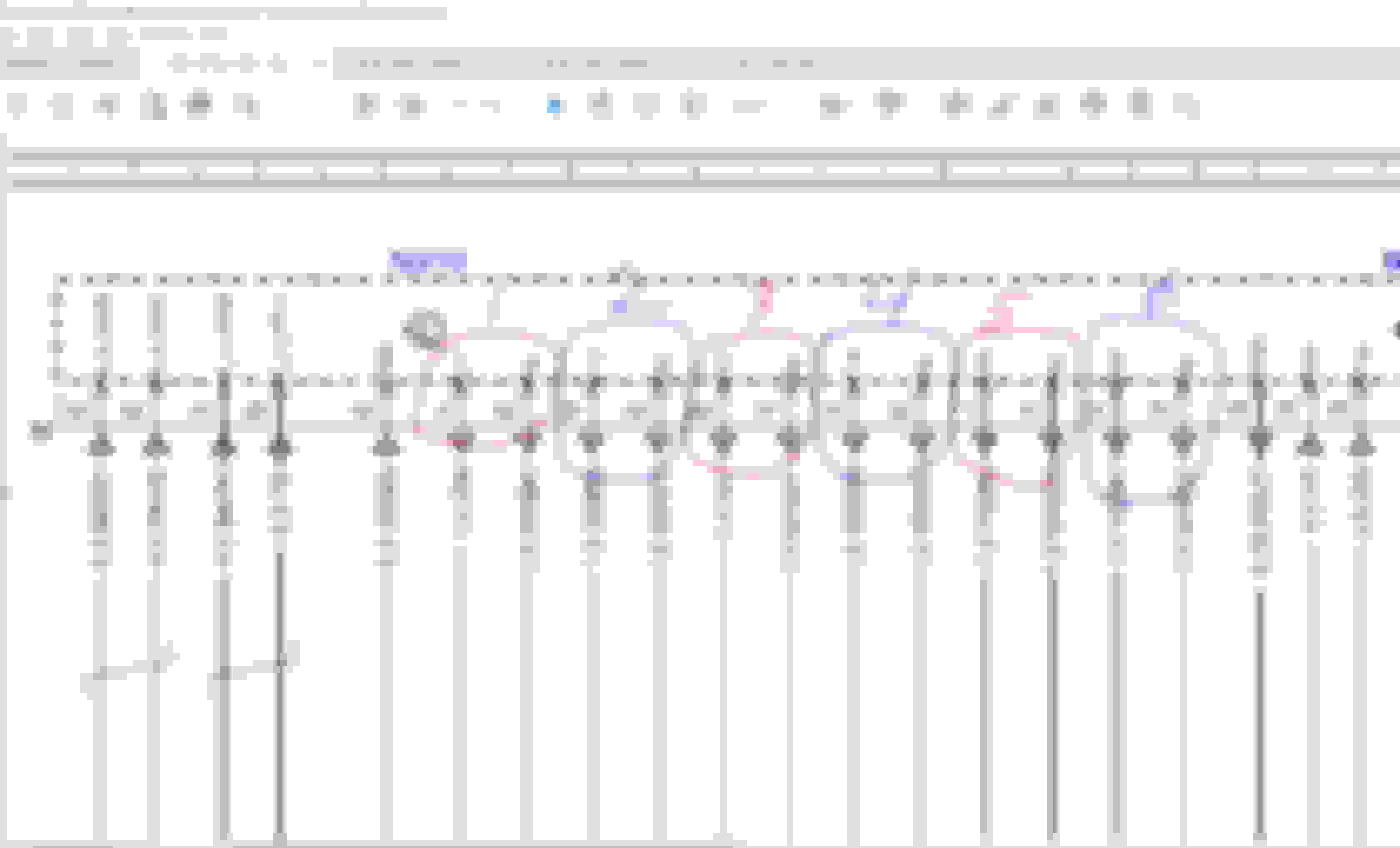
The COP is at the long connector with 96 pins. Please read carefully the pin numbers on your long connector.
Pin #9 is ZUE1 ( COP 1 signal at its pin 4 ), wire color is brown-green and baby 0.5mm size.
Pin #35 is ZUE2 ( COP 2 signal at its pin 4 ) wire color is green-blue, 0.5mm size
Pin #32 is ZUE3 ( COP 3 signal at its pin 4 ) wire color is green-white, 0.5mm size
01. Disconnect battery positive cable. Only the positive.
02. Ignition key not needed.
03. Disconnect ECM connectors, both the long one 96pins and the short one 52ish pins ( short one for safety sake).
The ground drawn for battery below, is best to use the main ground near the battery as per my marking.
At COP connector side
At ECM connector side
Pin #9 wire color supposedly is brown-green. Pin# 32 is green-white. Pin #35 is green-blue. All are 0.5mm size.
First color is base color, 2nd color is the thin stripe. So pin #9 is brown color wire with green stripe.
You must fuse the + power njection with 5A fuse for a 50Watt lamp load. The fuse is also to protect other sensors/devices if you poke wrong.
Please please make sure you are only poking ECM connector pin #9, #32 and #35, one by one and not all together, depending on which COP pin #4 you are testing. My old eyes usually need camera assist, zoom in using PC. Mark with sticker those #9, #32 and #35 holes to be safe. We are old eyes hahahaha.
Now, if you are comfortable with the instructions, go for it .
To be safe from causing any short circuit, the male connector as probe pins is to be sealed at its metal body using heat shrink, only the
contacting portion ( Mr Dick ) is to be exposed. Like below :
To load test the pin #4 of COP , you may stop using the voltmeter, because this wire during its duty....is carrying so little current, if the 50 watt bulb is bright, the wire/s are good already.
==============
When you do the test I mentioned, with proper MALE terminal of SLK2.8 and MLK1.2, you basically now own the best PIN FITMENT tool, which is the hubby of those females hehehehe.
I rigged test wires using the very same MLK 1.2 and SLK 2.8 , both male and females.
I use them naked, no connector plastic body. Hence I heat shrink them to prevent short circuit.
When I read that Kostal claimed ONLY 20 (if tin coating) to 50 (if silver coating ) insertions life as maximum and connection stay good, they are not kidding.
The female is the one which will "expand" out and be the bad intermittent contact, ALWAYS. I guess Mr Dick is always the lucky one, compared to Miss V.
By not using the plastic connector body, any movement of the male terminal is like a crow-bar effect towards the "tounge" of the female terminal.
The plastic connector body is like a great alignment tool for a very straight insertion, no wiggle wiggle.
This is why when disconnecting connector, more so multiple pins one like ECM 52 and 96 pins, always do it super straight and never at an angle.
My test wire, its female MLK1.2 tounge bite got loose so very fast because I use it naked : The 2 slim ones I marked DIY, those are female MLK1.2
That DIY female MLK 1.2 is the very same Kostal female terminal MB is using on most of their connectors if brand is Hirschmamn and Kostal and for ECM.
SLK 2.8 female terminal "tounge" is much more robust, but female MLK 1.2 tounge is very fragile.
Oky doky, when in doubt, we should discuss it again. Take your time to read my write up and study the connectors on the engine bay.
Remember, our old eyes is not helping here with these super tiny female and male terminals
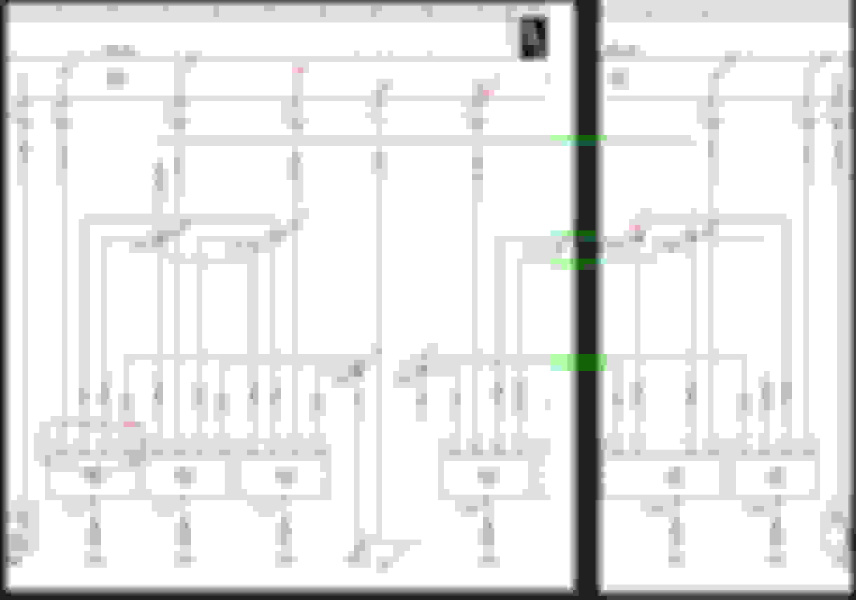
ALWAYS make sure the wire color/s of all the pins we discussed here, match to the schematic.
Wire color is another confirmation of correct one, but sometime it may make you confuse too if colors do not match 100%.
We shall discuss further is there is any wire color/s not as per schematic.
Last edited by S-Prihadi; 05-29-2023 at 05:45 AM.
Reason: add info
I honestly have not study the connector as deep as COP ones.
However the beauty of the female or male terminals MB uses, many are using MLK 1.2 for small size ones.
Item 11, the injectors. Also MLK 1.2.
So you best order 8 pcs of male MLK 1.2 terminal, at least. 6 of SLK 2.8 male terminals at least.
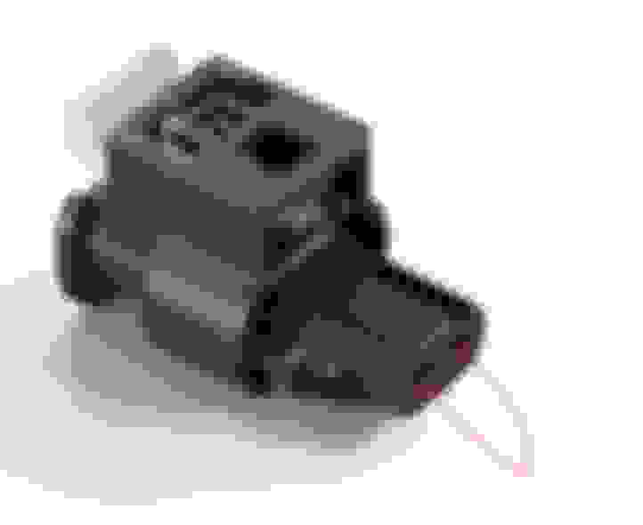
The injector on my engine is using Hirschmamn 2 pins/2 way, like below. Yours would be the same I am sure.
This is called Hirschmamn SealStar 1.2 family of connector. The side with curve/rounded edge is always pin 1, please verify it on you injector connector.
PINS FOR INJECTORS AT ECM 96 PINS CONNECTOR HARNESS SIDE.
WILL CONTINUE.....................
You only need to do injector 1 and 2 test. But make sure you unplug all 6 connectors to the all 6 injectors, if you want to be safe because pin 1 is for injector no 5, pin 26 is for injector no 4 and pin 27 is for injector 3, too close to your to be tested pins.
I mean , what if you poke wrong ? Sometimes me do that.... ha ha ha. Old eyes on small holes is never good.
Injector 1
Pin 2 wire color is GREEN, 1mm size. Labeled as EV1, injector 1.
Pin 50 wire color is white-black, 1mm size. Labeled as Sig, probably means SIGNAL.
Injector 2
Pin 25 wire color is green-brown. 1mm size. EV2
Pin 52 wire color is white-violet. 1mm size. Sig
01. Disconnect battery positive cable. Only the positive. 02. Ignition key not needed. 03. Disconnect ECM connectors, both the long one 96pins and the short one 52ish pins ( short one for safety sake).
04. Disconnect all 6 connectors to all 6 injectors. Or if you are comfy , disconnect connector of Injector 1 and 2 only.
05. Jump or short the injector connector, the one you want to test, say injector 1..... with 2 male MLK 1.2 terminals.
06. I am showing test only for injector 2, you by now should be able to do the same test for injector 1.
I hope my ugly drawings are clear
Have fun and I hope only wires, or splice or pin fitment is your issue and not the ECM driver.
Last edited by S-Prihadi; 05-29-2023 at 06:26 AM.
Reason: Continue post
Mr. Prihadi, that is an amazing amount of information. I have read through it and trying to absorb it all. Obviously you walked this road before and your experience is golden. Thank You
I do not have the connector pins needed to do an accurate test. I will need to acquire some more tools. And read this about 4 more times before tracing these down. After all that it may still be an issue inside the ECM but this needs to be done first. Thank You
Mark
However, injector and COP is not a constant load, it is a pulsating load with duration of 3/1,000 second and at 600 RPM idling, it will be approx 300x a minute of these pulses, as such certain test on the above video
if expected to be live load of the device itself, it won't work for injector and COP, but a test bulb as load will work to test the wires.
Don't know if I messed this after reading through all the information but I never seen anyone mention Plug Gap. When you check Cyc # 1 is there gasoline on the plug? Yes or No? If yes, you may have a injector problem but if No, then you are in good stance. Check the Plug Gap as that can effect the performance and cased the issue to clip cyc #1 into a CEL.
Plugs are new Iridium Bosch and at .028 if I remember but yes all gaps checked. 3 different injectors have been in #1 cyl with no change so far. Narrowed down to wiring or PCM at this point. Thanks
Don't pull your hair, it's just battle stripes & No one got hurt.
Way back after I started researching cures for random misfires, I came accross some of the same roads you did.
I upgraded the skinny COP Power feed line to 14.AWG stranded conductors.
The truth here is you want to be ready to pass the top of current spikes, not only the average value.
The main topic here is the firing sequence of cylinder 01 by multiple sparks. How can this be so popular with all our pals ?
What's involved here is:
lean gasoline vapors
cylinder pressure
working heat-range
spark burst timing
VVTimings
sloppy dual distribution chains
....
What could go wrong, right?
Imagine the firing solution as a quadrant... you can get closer to one corner at the time. One of the job of the smart Bosch EFI is to be the best at lean firings.
Misfirings are too far out of control. You loose performance without impacting the environment.
It works like this:
Cylinders that can't burn well get leaned out. When that affects the whole engine is when vibrations at RPM start following the engine in higher speeds.
But what causes that combination?
Timing, not fuel, not spark.
When the crank speed is irregular the exact engine timing remains poor.
We need smooth everything for great mixture matching:
smooth ignition spark
smooth belt tension: yes!
smooth load
What naturally wrecks avoc with timing are the amazing HYDROLIC CHAIN TENSIONERS that allow camshaft reversals. That is EXACTLY WHAT LOOSE TIMING IS !!! PLAIN CENTER STAGE: THE CAMSHAFTS TIMINGS ARE LOOSE.
When these bad corrective numbers are learned... would be dumbo Bosch ECU keeps trying to correct from old history. It has no way to guess right without professional Star blessing's.
Last edited by CaliBenzDriver; 06-01-2023 at 12:57 AM.
The engine timings are based on sensors tics salted with learned corrective factors.
I think you should reset/retrain the camshaft corrections.
BEYOND MISFIRES:
Once you can get beyond the misfire fault stage, we can work at smoothing the variability of irregular jittery timings.
These simple factors are what is used to de-tune the modern Bosch injection engine.
The outcome is lean misfires... lack of bottom torque power (heavy car feeling instead of flying carpet), poor accelerations caused by lean mixtures...
We can do better than simply a basic "no code" condition to get a smooth powerful honest engine.
Welding the loose sensor plate was a great call. What led you to zero down on that... a DTC?
Last edited by CaliBenzDriver; 06-01-2023 at 05:44 PM.
Welding is an exaggeration. The sensor wheel just needs to not rotate so I initially was going to add a roll pin to keep it from rotating on the cam shaft. Once I had it apart the roll pin idea did not look good. I drilled the small hole in the cam sensor plate and just tack welded it. As small as I could but now there is a bump the sensor wheel would need to go over to spin on the camshaft. It is welded but barely, the bump is serving the purpose the roll pin would have done. Thanks for thinking on this problem, I do need it fixed and out of my garage. Since repair, cams show to be in sync, tensioners are new. Scan tool used to re set Cam positions after repair. Obviously I don't know what the problem is yet and can't rule out anything since all my efforts so far are not good. Still odd to me that it can come and go. I still need to get a set up to load test my wires and move on from there. I appreciate the feedback and ideas.
I think the main problem is that you are using Bosch and not NGK. One of the issues not using NGK is that not all sparkplugs are made the same to manage GDI engines. My wife had a Hyundai that stated in the book to use only NGK Iridium Laser (same as my car uses) but she could not find NGK Laser for her own budget so an shop that she took her SUV to change the spark plugs, installed Champion with the correct gap. However after 15-20,000 km the car started to misfire badly. When I looked at it, I noticed the end of the spark plugs were destroyed and when I checked in the cylinders, there was no mental but they sparkplug tips had completed melted. I have never seen such a thing. Anyway, I purchased the NGK and as of now and over 30,000km, no a problems.
Also, if you check all the timing, compression and coils, you may have a bad ECU.
I don't have a visual of your tack weld...
Be reasonably sure the camshaft sensor can not get confused from this sort of additional magnetic spot ... as if this was a 7 cylinders engine .
I am not a Xentry guy that can help you reinitialize the camshafts system - That's where I'd focus. Third party scanners may be a limiting factor for this advanced job.
you want to test that undersized coil wiring is or is not causing Cyl.1 misfires.
what i was thinking is you can double-up/bypass existing coil harness with a 14.AWG stranded conductor in parallel.
What I mean is you don't need to cleanly remove the existing wires and replace with new... just add a path wired in parallel quick'N dirty for testing.
This low-impedance feed circuit should help No1 fire a bit better, both (+) and (-) lines, one cylinder for now.
Hope this help you go pass that step.
(I did that COP wiring upgrade over 10 years ago on my 3.2L Honda V6: zero issue with still original Denso COPS most ppl replace because of lean misfires).
I even tried overvolting my coils primary with 18Volts instead of 14V...
Long story short: the issue was unstable timings, not spark!
Last edited by CaliBenzDriver; 06-02-2023 at 03:36 PM.
Partial update today. I have studied the notes and testing, and verified that I agree with the notes on testing the COP, Coil.on Plug system for this engine. M276.
Some initial notes I will share. No idea if it is fixed because in this car you can’t test.anything till the manifold is back on the engine. You can’t see anything to start testing till you remove the manifold so I have some results but no idea if it is fixed.
Started testing the COP wires as instructed above. With my battery charger hooked up and running my voltage at the battery is 14.16 Volts.
First check I went to wire #4 in the COP, tested at the COP connector for cyl 1-3. I found about one half volt voltage drop on these wires that all go to ground at the front of the valve cover. So I removed the screw from the ground and cleaned not only the wire connector but the inside of the threads for this connection. On assembly I had zero change? Screw torqued to 96 inch pounds. Strange. I pulled the screw and took it down again, tightening slowly by hand I felt it just stop and not tighten anymore? No gradual increase in torque load just a quick stop. Wire is not loose to the touch even with a pretty strong turn of the connector it stayed put. I decided this screw might be bottoming out in the hole. I added one thin washer to the screw and re installed. The Voltage drop of .5V is now gone. Now drop is down to maybe 20 milivolts from the previous 500 milivolts.
Could this have been my problem??? Maybe but I don’t think so.
Next test. Checking Pins #3 and #4 at the COP connector. The wire to the 3 position in the COP connector is the power source from fuse 23 20amp fuse in the front SAM. The Wire to the 1 location in this connector is a second ground source for the Coil. Testing these wires loaded with the power coming from the COP power at the 3 pin, ground from the 1 pin loacation. I have two lights connected to this circuit that are supplying a 4 amp load. If I had a stronger light for testing I would have used a larger one for more load, this is a 20 amp circuit. With battery still on charger and showing 14.16V I started checking my connections. COP#1 shows 12.8V? Checked COP2 and CCP3 and got 12.8 or 12.9V??? Not close to 14.16V. Connected my meter to the #1 COP power wire again at 12.8v. Now I removed the ground from this COP #1 connector and went to the known good ground and my voltage jumped to 13.91, slight drop from 14.16 but with all the connections I figure this is a very good power source even when loaded with my test lights. The problem is in the COP grounds that are plugged into the #1 position in the COP connector. I Start moving down the harness from the #1 COP connector towards the rear of the engine to the High Pressure pump around and behind it, to the center of the engine rear and to the other cylinder head. While I am searching and sqeezing the wire harness I am seeing movement on the multimeter. 12.8 to 13.3V bouncing constant as I move and jiggle the harness. As I got behind the Hight Pressure pump at one of the tie downs for this harness as I wiggle the voltage jumps to 13.2V to 13.5V no longer dropping down to 12.8 like I had at the start? I found one specific spot where the harness was warmer than the rest at this rear tie down, only reason for heat would be a bad connection, there is no activity in the harness. After my wiggle and finding this spot where the wire harness was warm I started re checking my voltages back to the #1 COP connector. No longer have 12.8V, I now see 13.45 at the COP cyl #1 pin 3 connector so the ground is now better after the wiggles. Going back to the spot that was warm when I had 12.8V in this connector that spot has now cooled off, feels about the same temp as the surrounding wires.
I suspect a bad connection or pinched wire is in the harness at this spot behind the High Pressure Pump, by squeezing and moving the bad spot the connection is improved but not yet good. I need to free up the harness for access to check the wires at this spot that got hot.
I checked the bank 2 COP just as a test. The #4 Cyl tested 13.91 at the COP power wire in pin 3, the ground was good even tested loaded. Loaded I saw a 300mv drop at this ground.
Loaded on the Bank 1 side where my problem exists Cyl 1 had 484mv voltage drop. #2 had 430mv and #3 had 484mv voltage drop.
No idea how these finds could have made just cylinder #1 misfire, BUT, before the car came to me a previous shop had replaced the #3 coil and spark plug? When I got it #1 was misfiring and I found the problems with the Cams being out of sync.
So it is not fixed, yes I found some issues so far but No I have no idea if the engine will run after the grounds are corrected.
I still need to check the #4 position COP connector wire which is the trigger wire going to the ECM, this is a fine wire for a 5V signal from the ECM to activate the Coil when it needs to fire.
So even though ground connections had been checked to make sure they were clean and tight, one ground had a slight connection issue that showed up under load and the harness had a voltage drop of as much as 1.2 Volts that showed up under load before I wiggled the harness and gained most of that back. Just to be careful I will check the trigger wire next before searching for cause of the voltage drop but at least by finding the warm spot in the harness I know exactly where to look first. I think it is on the road to recovery. So initially the finding of 12.8V at the #1 COP connector was 1300 milivolts or 1.3V short of battery power which as 14.16V. When loaded, so that may be a solution.
Last edited by Westlotorn; 06-02-2023 at 06:44 PM.
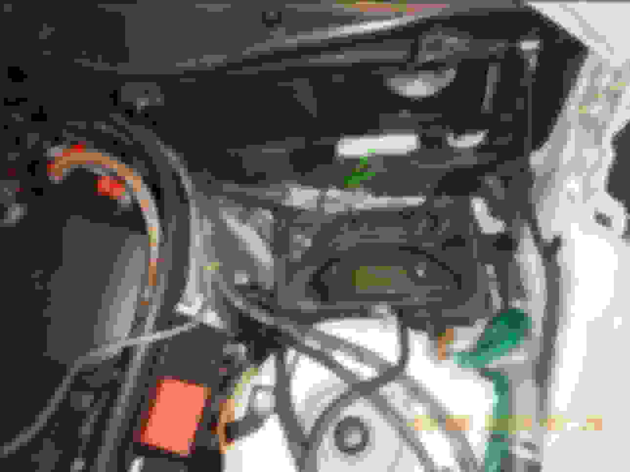
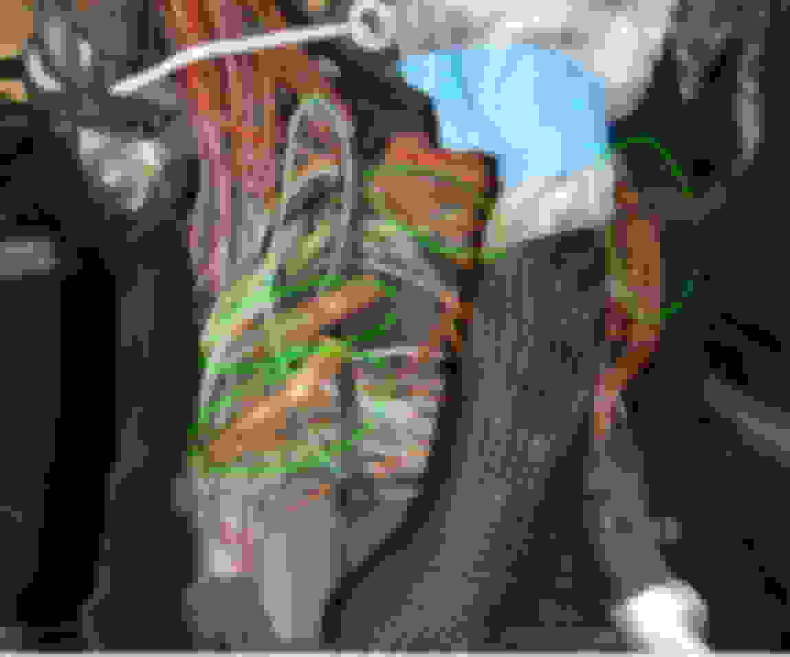
Spent the afternoon tearing into the harness and found the bad connection right where the warm spot was inside the wire harness at the back of the engine. For some reason Mercedes had 4 wires, all grounds, brown in color routed towards the driver side across the rear of the engine inside the wire loom with 41 other wires all in the bundle. These 4 are connected with the crimp, glue and cover as described by Mr Prihadi. His notes were the lifesaver that got me through this part. I cut out the connector Mercedes installed, could see no way to take it apart. Soldered the 4 wires together and added a 5th wire, 12 gauge and extended the brown group of 4 by about 12” to allow me to ground them again as a back up.
Tested the wires to the fuel injectors, all tested good under load. Tested the Pin 4 from the COP connector all the way to the PCM, All tested perfectly under load. Now with the ground failure found, which only showed up under the loaded condition I know all my wires are good. Still have no idea if the car is fixed or if I am just getting closer to fixed. In the morning I will throw the manifold back on and fire it up to see if there is any real progress. No doubt it had a couple issues now corrected but I do not know if this will fix the misfire. Fingers crossed! Thanks again to all that helped.
PS: My new copy of the WIS finally showed up today. Would have helped a week ago.
01. West wrote :
First check I went to wire #4 in the COP, tested at the COP connector for cyl 1-3. I found about one half volt voltage drop on these wires that all go to ground at the front of the valve cover. So I removed the screw from the ground and cleaned not only the wire connector but the inside of the threads for this connection. On assembly I had zero change? Screw torqued to 96 inch pounds. Strange. I pulled the screw and took it down again, tightening slowly by hand I felt it just stop and not tighten anymore? No gradual increase in torque load just a quick stop. Wire is not loose to the touch even with a pretty strong turn of the connector it stayed put. I decided this screw might be bottoming out in the hole. I added one thin washer to the screw and re installed. The Voltage drop of .5V is now gone. Now drop is down to maybe 20 milivolts from the previous 500 milivolts.
Could this have been my problem??? Maybe but I don�t think so.
I think you meant pin/wire #2 at COP and not #4. That #2 is additional ground which ends up at W11 ground torque screw, right bank (Bank 1) front side of engine. Pin #4 of COP is the baby smallest wire from ECM to trigger COP.
The length of the torx screw on MB , some are 12mm and some are 16mm. Becareful of using the wrong one when one is doing repairs and removing these shorts torx screw. They look so identical at a glance.
The engine ground, example W11 is using torx screw. Where on chassis, ground uses a nut because MB welded male stud as ground post.
W11 ground on engine cover is not super "clean" ground as its electrical travel/distance is as follows :
Main chassis ground wire under the car ( not in MB wiring diagramand I call it W-TF ground wire ) to the engine's starter motor bolt>>>via lower engine block>>>finally to cylinder head. There are gasket and female threads which may be not so clean.
If there is doubt during the test, use a good jumper cable of 2mm size, connect it to W11 torx screw and to main negative stud near battery called W10, that brass thingy at suspension strut mount.
02A. West wrote:
Testing these wires loaded with the power coming from the COP power at the 3 pin, ground from the 1 pin loacation. I have two lights connected to this circuit that are supplying a 4 amp load. If I had a stronger light for testing I would have used a larger one for more load, this is a 20 amp circuit. With battery still on charger and showing 14.16V I started checking my connections. COP#1 shows 12.8V? Checked COP2 and CCP3 and got 12.8 or 12.9V??? Not close to 14.16V. Connected my meter to the #1 COP power wire again at 12.8v. Now I removed the ground from this COP #1 connector and went to the known good ground and my voltage jumped to 13.91, slight drop from 14.16 but with all the connections I figure this is a very good power source even when loaded with my test lights. Sweet.....
02B.1. West wrote: The problem is in the COP grounds that are plugged into the #1 position in the COP connector. I Start moving down the harness from the #1 COP connector towards the rear of the engine to the High Pressure pump around and behind it, to the center of the engine rear and to the other cylinder head. While I am searching and sqeezing the wire harness I am seeing movement on the multimeter. 12.8 to 13.3V bouncing constant as I move and jiggle the harness. As I got behind the Hight Pressure pump at one of the tie downs for this harness as I wiggle the voltage jumps to 13.2V to 13.5V no longer dropping down to 12.8 like I had at the start? I found one specific spot where the harness was warmer than the rest at this rear tie down, only reason for heat would be a bad connection, there is no activity in the harness. That would be the splice Z6z1 most likely, or if not a splice it is then a wire copper strands breaking inside its PVC insulation from tight bend and vibration. If you have a thermal imaging camera, FLIR type not temperature number type....that will be a good tool to use. Or keep load long enough to make more warmth.
To note : I still can not find where the hell W16/5 ground is, which is for pin #1 of all COP.. MB WIS is not showing its actual location...Dugghh.
The links brings to nowhere. In WIS you can click document number and it brings to next document.
02B.2. West wrote: After my wiggle and finding this spot where the wire harness was warm I started re checking my voltages back to the #1 COP connector. No longer have 12.8V, I now see 13.45 at the COP cyl #1 pin 3 connector so the ground is now better after the wiggles.
Going back to the spot that was warm when I had 12.8V in this connector that spot has now cooled off, feels about the same temp as the surrounding wires.
I suspect a bad connection or pinched wire is in the harness at this spot behind the High Pressure Pump, by squeezing and moving the bad spot the connection is improved but not yet good. I need to free up the harness for access to check the wires at this spot that got hot. If you test lamp is only 4 amps or 50 watts, and that suspected area is warm, it must be a real bad connection.
Spent the afternoon tearing into the harness and found the bad connection right where the warm spot was inside the wire harness at the back of the engine. For some reason Mercedes had 4 wires, all grounds, brown in color routed towards the driver side across the rear of the engine inside the wire loom with 41 other wires all in the bundle. These 4 are connected with the crimp, glue and cover as described by Mr Prihadi. His notes were the lifesaver that got me through this part. I cut out the connector Mercedes installed, could see no way to take it apart. Soldered the 4 wires together and added a 5th wire, 12 gauge and extended the brown group of 4 by about 12” to allow me to ground them again as a back up.
Tested the wires to the fuel injectors, all tested good under load. Tested the Pin 4 from the COP connector all the way to the PCM, All tested perfectly under load. Now with the ground failure found, which only showed up under the loaded condition I know all my wires are good. Still have no idea if the car is fixed or if I am just getting closer to fixed. In the morning I will throw the manifold back on and fire it up to see if there is any real progress. No doubt it had a couple issues now corrected but I do not know if this will fix the misfire. Fingers crossed! Thanks again to all that helped.
PS: My new copy of the WIS finally showed up today. Would have helped a week ago.
The wires you speak of is BROWN only or Brown-White ? You said 4 wires in the same connector ( spliced ), but color is BROWN.
If Brown only, that is the splice which ends at W11 ground. Would be splice Z2/1 if for Bank 1 - Right Bank. 3 wires total.
If Brown-White, that is the splice which end at W16/5 ground. Would be splice Z6z1 , if for Bank 1 - Right Bank.. 4 wires total.
W16/5 is true negative power/ground. 1.5mm wire
W11 is noise control ground, 1mm wire.
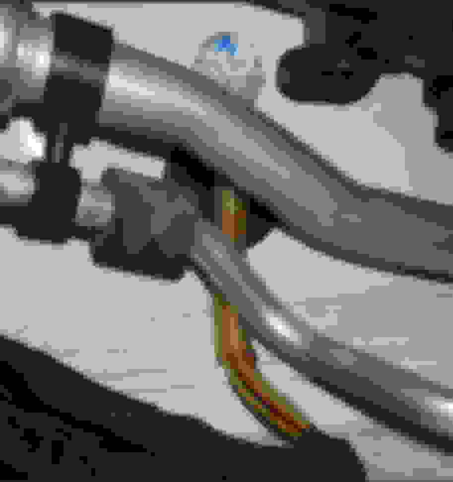
The connector was like you described, 4 wires into one connection/splice, banded by what looks like a brass band, covered in plastic and what looks like cosmoline, I have not seen cosmoline used in years but it looked like this stuff. The military used to use cosmoline to protect parts that were being shipped over the ocean for protection against salt water rust. It is kind of sticky, almost clear, but hard to get off. I will try to post some pictures I took of this connection before and after I cut it out. All wires look brown to me but this connection is where my warm spot was while testing and where I wiggled the wires and picked up the lost volts. Assembled with new solder and all wrapped up now so I can't look to see if the colors are correct but I see no stripes on these brown wires. As mentioned these 4 wired dead ended right in the middle of the wrapped wire bundle, no way to see it or touch it without cutting into the wire loom. Once again, Mr Prihadi, your extended help saved my bacon tracing these connections down. I had a lot to learn about load testing wires. I will assemble the rest of the engine tomorrow and test it. Fingers crossed but a little hopeful of success.
Wow...... that does look like poor crimping, not a round beauty crimp.
If the crimp is good and round, it will look like below.
I think MB screw up the color for the actual wires , it sure looks brown only, with no small white trace.
Above and my M276 3.0 TT too..........Dang, they looks like no soldering, only crimp.
So, MB protocol is seems to only solder when the connector is open ended with eyelet for screw or stud.
So, that means I got homework for next year. Year 10th rejuvenation program.
I will re-do all splices and crimp it and solder it too. I can't get the cosmoline but I can use heat shrink ....double wrap the crimp and get the one with adhesive lined ones. "Cosmoline is the genericized trademark for a common class of brown, wax-like petroleum-based corrosion inhibitors, typically conforming to United States Military Standard MIL-C-11796C Class 3."
=====================
Mr. West,
I am sure you have found your "misfiring cause". I like it when one work very hard to get to the bottom of the root cause.
The DTC you have does not tell which one goes bad first, COP or injector...........it only explain there is a misfire on X cylinder.
Tomorrow we all awaits your good news, the final confirmation.....yipeeee.
Just in case you have not seen and clean this ground stud, but it is actually exist in your M276 3.5 NA LEFT HAND DRIVE version car too....... do check it.
I could not find this ground information on the WIS, it could be the W16/5...the ground I could never find..although the wiring size and wire quantity is different.
Remove battery and battery tray.
FOR MY ENGINE
By wire color and qty, this is Z6z2 ( for COP ), but MB wiring diag shows these 4 brown-white will go to X26 and X26 becomes 1 brown only wire 1 unit of 2.5mm.
So I hope ur car has the same set up, but at RIGHT side .
 05-28-2023, 02:10 PM


 ) is to be exposed. Like below :
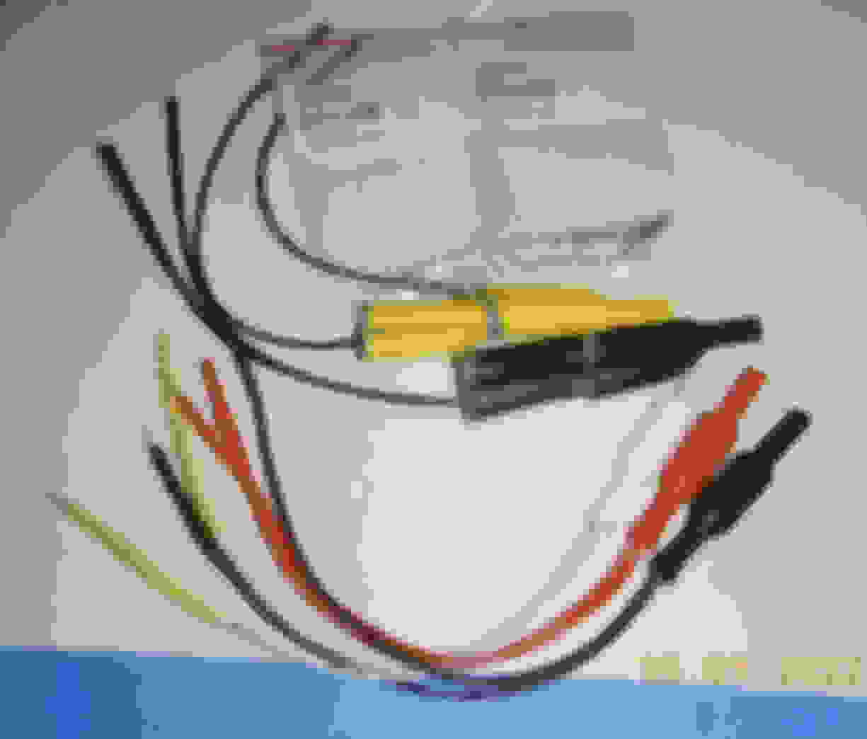


 and I call it W-TF ground wire


 I like it when one work very hard to get to the bottom of the root cause.