When you click on links to various merchants on this site and make a purchase, this can result in this site earning a commission. Affiliate programs and affiliations include, but are not limited to, the eBay Partner Network.
Well, after all this I am sad to report. Misfire condition is worse than ever. Not coming and going at all, Cyl 1 is dead. I did check under the battery tray for one more ground but on this American Spec car there is no ground under the battery tray. I had it completely out. Good thing I guess because I found the battery vent tube was down under there and not hooked up. Back to the drawing board. Yes I revisited the #1 Coil and Spark Plug. After short run without firing #1 is wet. Installed new Plug, swapped Coils with #2. Fired up and same exact situation. #2 fires perfectly. #1 is dead, constant misfire. All 5 other cylinders are firing with zero misfires regardless of me swapping the coils. Problem stays with Cyl #1. There is no doubt we found a serious issue with the grounds and repaired it, backed up by load tests done. I hoped this would fix the #1 misfire but it did not.
I did not tighten the female connectors on the Coil On Plug or at the PCM. If they are loose causing this I did not know how to remove and tighten them. Thought I might cause more damage than good So I hoped the problem was with the ground faults found. The coil connector has been on and off so many times I do not doubt the connection may now be bad. I bet that coil was off several times prior to me getting the car and I have had it off at least 10 times now. Pretty much same for #2 but it has no problems at all.
Looking at coil function while driving. My scan tool has one option available. Smooth Running of Engine, I think this shows the variance of work at each injector. 5 good cylinders will vary between -1.500 and plus 3.500, the #1 injector when misfiring always reads up around 12.00 which I think is measured in volts but it does not say. When #1 was working on and off before it would read + 3.500 or so but when it started misfiring it jumps to 12 +. Even at +3.500 it was on average about 2.00 higher than the others while observing. Now it stays at 12 +. It would help to know exactly what this is measuring. Maybe it is sending 12V to the injector and it is not providing fuel? Maybe it is sending 12V but the PCM is never sending a ground signal to fire it??? It might help track this if I knew. At least I know the wires connected to the COP are good, the grounds are good. What I do not know is if the COP connector is actually connecting or if the PCM is actually sending the proper signals. More learning needed and I am burning out on this car. About ready to call my friend and tell him I can't figure it out.
Edit: Just had a thought, I have a timing light that just might connect to the #1 plug wire so I could see activity while running. Since this is #1 I could also see if it is firing at the timing mark on the crankshaft. Duh, this should have been done at the very start of this adventure. On newer cars like this Mercedes M276 timing is controlled by the computer and crank sensor so it is a tool we just don't use on these cars but it might give a new clue. Back to work.
Edit: 2: Timing light shows the #1 COP firing every single time. #1 is firing 18* before top dead center?
So: COP is working, Timing is correct at idle, 3 different injectors have been installed with no real change since I started playing with it.
Still could be no signal from the PCM to fire the injector or bad connections at the injector or the PCM. I tested wires they passed the load test.
Last edited by Westlotorn; Jun 3, 2023 at 04:13 PM.
Perhaps listen to Dan , it is the last part of the premise that the failure is fundamentally electrical. I think no one here want it this ti be the source, $$$?.
NOTE: i am not expert on these things, learning here..
Good Video by Dan, I think with the timing light showing the coil is sparking each and every time it should the Coils are now ruled out. The PCM is certainly still a possible issue. Unfortunately the injectors are under the intake manifold on this car repair is more difficult. You can’t try one thing and start the car to examine results without taking time to install the manifold. That goes pretty quick now with all the practice but sure gets old.
Here is my 2c guess
1 - you clear the codes
2 - re scan before starting the engine, if no codes I assume , big one, the ECU verified all the coils are there and ready to roll
3 - scanner in Data stream mode to monitor the misfire, and trims
4 - start the engine, and see if #1 works for even a few seconds. If it dies, but something else is off ECU turned off; however, if it never works ECU driver for coil #1 is busted
5 - monitor ECU driver for coil #1 would be great of course as Dan did it. Easier said than done though
let us see what others think of that line of thought.
I think you are on the right path Juanmor, I have been trying to get the new version of WIS to load hoping to find more information. Loading is taking forever as it did the first time, but no idea if this version will work.
I will try the engine start with clear codes and watch my scanner. I think it runs maybe 10 seconds before it records mis fire events in this car. I thought there was just a lag between start and the system recording?
Don't raise the white flag till you test pin fitment. Have you got the male MLK 1.2 and SLK 2.8 from that shop ?
Also slowly inspect that the female terminals has not moved "inward" or out of place. It can happen.
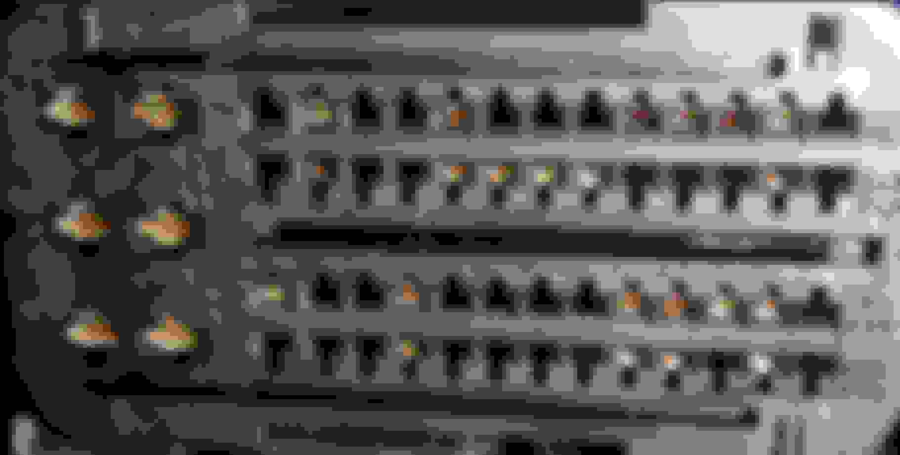
Below is equivalent ECM connector, the shorter one, I bought for testing purpose to study how the female terminal lock itself to the cavity.
The green arrow or right side female terminal, I on purpose do not push maximum-IN , to simulate a worn-out female terminal locking mechanism..
Below are my ECM connectors, archive photos of May 2021. I need to take photo and study the female terminals sitting position using camera and PC. Me old eyes sees better on PC
You must make sure all female terminals are sitting maximum outwards and no damage on its square shape "mouth".
I know it is frustrating, but this is the given curse of such mini sized female terminals.
I need to elaborate on female pin looking good aka parked well but actually not locked, and will be pushed inward by male terminal during the mating.....hence bad contact.
When many wires are bundled up together, cable tied or taped together, the wire jacket acts like a spring.
So you must use your male terminal SLK 2.8 and MLK 1.2 aside from pin fitment feel, also make sure the female terminal is truly locked in place and not sliding backwards when mating happens, due to lock failure.
Depending on connector plastic body design, the female connector may lock itself using its own locking tab or the connector body also has a plastic blocker plate.
If I recall on M271 big 96 pin connector plastic body, the MLK 1.2 female terminal does not use its own metal locking tab, but instead it has a raised shoulder and that raised shoulder get lock by plastic blocker plate of the connector body.
Imagine the green box #1 is the plastic blocker plate of the connector body. So the female terminal shoulder acts as the "lock tab".
However, there is a real springy type of lock tab on the female terminal too. Some connectors may use this springy lock tab of female terminal to do secondary locking.
Compression tested with both a compression tester and a leak down. Compression not the issue. 2-6 all fire perfectly with no misfire so no need to add more work. I am zeroing in on the #1 injector to find out why it is not working properly. Since it performed the same with 3 different injectors in that #1 cylinder the data instructing the injector is not getting there. Wires are now load tested good so it must be a connection of these wires or the PCM is not sending the signal.
correct, and with Surya' description my suggestion only proves the problem may on the other end of the harness; however, it does not say on which side of the connector : engine side, or ECU side.
Would you mind taking high resolution photos of the ECU connectors, both sides: harness connector and ECU pins? Perhaps looking at them statically, and zooming something pops up. 🤞
Wasted 4 hours loading the WIS system, one of the final instructions says it needs to run on Windows 7, this is supposed to be a 2020 version of WIS. I have Windows 10 of course so money and time wasted. I guess I need to pull that manifold again and get a better look at the connectors. Try to take pictures. One thing I noticed last night. The #1 injector connector on the wire side did have a small white spot on the connector. If it was a spark plug boot I would think it was a sign of misfire? I checked the other 6 connectors and they did not have this type mark all were clean. I cleaned it well with electrical cleaner and installed it last night. Might have been a boo boo but I had checked the wires at the connector by probing about 4 inches away from the connector and all showed good to the connector female side but I did not load these wires when testing and I did not have a way to make sure the female was tight.
Wasted 4 hours loading the WIS system, one of the final instructions says it needs to run on Windows 7, this is supposed to be a 2020 version of WIS. I have Windows 10 of course so money and time wasted. I guess I need to pull that manifold again and get a better look at the connectors. Try to take pictures. One thing I noticed last night. (01)The #1 injector connector on the wire side did have a small white spot on the connector. If it was a spark plug boot I would think it was a sign of misfire? I checked the other 6 connectors and they did not have this type mark all were clean. I cleaned it well with electrical cleaner and installed it last night. Might have been a boo boo but I had checked the wires at the connector by probing about 4 inches away from the connector and all showed good to the connector female side but (02) I did not load these wires when testing and I did not have a way to make sure the female was tight.
02. You do not have yet MLK1.2 and SLK 2.8 male terminal ?
01. Whitish corossion stain ?
Due to 200V maximum voltage of injectors, I do not think it is the same as iginition 20,000V whitish residue high voltage leak we see on spark plug boot.
======================
West wrote :
Well, after all this I am sad to report. Misfire condition is worse than ever. Not coming and going at all, Cyl 1 is dead. I did check under the battery tray for one more ground but on this American Spec car there is no ground under the battery tray.
I had it completely out. Good thing I guess because I found the battery vent tube was down under there and not hooked up. Back to the drawing board. Yes I revisited the #1 Coil and Spark Plug. After short run without firing #1 is wet. Installed new Plug, swapped Coils with #2.
Here it seems the COP went dead first and not the injector, hence spark plug is wet with fuel.
Still need to truly confirm COP or injector stop working first ?
Of all 4 wires at COP connector, only 1 goes to ECM. The trigger, a low power 5V signal for COP. Pin #4.
The good thing about your COP is, all high load pins/terminals #1, #2 & #3 none goes to ECM.
Question 1 : How do you connect your test light (load) to the female terminals #1, #2 and #3 of COP when you do not yet have SLK2.8 male connector ? I mean what "male terminal" did you use ?
Before we condemn the ECM, we must test pin fitment.
========= ECM TESTING ===============
I will also be doing some thinking on how you can use simple test light ( the wired type screwdriver shaped test light ) to read COP 5V trigger pulse and to read the pulse of injector too.
I will get back to you when I can find a safe one for the injector, COP is easy.
You will need back probing needle, no choice. Like this one :
With safety strategy ECM will be doing by cutting off COP and injector if misfire is detected, I know this test is not so easy without a scope as time based data logger.
However, we should try without a scope.
To answer your question on COP ignition event 18 degree before TDC.
In a spark ignition internal combustion engine, the purpose of advancing the timing of the engine spark is to get past ignition delay. Ignition delay occurs during the time that it takes to fully ignite the mixture with a spark plug.
That is typically 15-35 degrees before TDC (top dead center) of the power stroke depending on the engine speed. https://www.enginebuildermag.com/201...engine%20speed.
This is my engine ignition timing advance and retard, from cold start ( 30C ) to 33 seconds of running. Logging is at 5HZ or 5 data points per second. From our OBD2 we can extract this data.
Attached the master file for your viewing. I use Banks Gauge.
I do fully understand Timing and where it should be at idle. I am good with the 18*, that is normal. I have yet to buy a scan tool that can Scan the injector fire sequence.
No I did not buy any pins for testing so far. I have back probe tools and many connectors but for the tests yesterday I made my pins. Took small finish nails, pounded them flat in the shape of the pins I needed and then ground them down to the width I needed. Sounds involved but did not take 3-5 minutes, yes I just used my eyeball to judge thickness and width but they worked without excess press in force, felt normal. I did have to make 2 sizes, the PCM connectors are smaller. I did not make any female connectors I just used care and touched with my back probe to test.
I took pictures of the connectors in question tonight. I will try and post. The fuel injector connection sitting in the engine was hard to get a picture that showed anything.
The dimension of the blade for male LMK 1.2 and SLK 2.8 terminal : in millimeters.
By position, all the female terminals looks good. Maximum forward position.
I am sure all locked well, because you have probed them from the front using your DIY male blade....right ?
Injectors
COP
MLK 1.2 male insertion to its female is a very low friction one. I initially do not believe it is that "loose" when I managed to buy them brand new naked female and male terminals.
The plastic connector body is the one creating the good friction .
You know relays male to female friction fit when we used to DIY connector for them, relay ones are so high friction and even much higher than SLK 2.8 type.
The friction of MLK 1.2 is like even less friction than micro pins people use for Rasberry Pi electronic board.
Last edited by S-Prihadi; Jun 4, 2023 at 06:09 AM.
Reason: add info
WILL NOT WORK !!!! :
01. TEST LIGHT of 130 milliamps @13Volt , to show activity of COP pin #4 which is the 5V trigger for COP......... too much load for that 5V trigger. My engine combustion sounds "weird".
===============
02. Will be no use also, using test light for injector on our M276. because the injector spray strategy is complex. Not a single spray event, but multiple spray events and depending on how cold/warm the engine is.
Below, few seconds from cold start. RPM still at 950.
Zone A1 and A2 of the green channel C, is COP #1 firing event. Marker B and C of the blue channel A , is injector #1 voltage aka fuel spraying. Red Channel B is the current consumed by the injector #1.
So after combustion event A1, marker B and C is early fuel spray for the next combustion event A2.
At A2 , there is also fuel spray right before COP fires which if a single spray injector strategy... that would be the main fuel spray.
Below : A1 combustion event, zoomed.
Here is my scope even a floating ground unit, can't withstand the high voltage from injector ( blue channel A ), because my green channel C which is the 5V voltage to trigger the COP get distorted too at the same time injector is energized.
I need to buy the expensive differential probe, if I want to scope injector voltage while also scoping other voltage signals on different channel.
A1 combustion event, with green channel C, turned OFF.
Blue channel A is the injector voltage.
Now you can see from the red channel B.... the piezo current draw and current output like a generator. Consume 4 amps, produce output also 4 amps.
A1 combustion event, not so zoomed, so that we can see the COP #1 ignition event at green channel C which took place 1.182 milliseconds after injector #1 start of spraying fuel.
=====================================
My engine firing order and timing details. I am sure this is identical to M276 3.5 NA
===================================
To not blow up my scope, I am now scoping for voltage ( contact type ) of injector #1 only and the other two channels I use current clamp ( contactless )...... also less noise from injector.
Engine has warm up to approx 65C but not yet operating temperature of 80C minimum. So here ECM still is using unique fuel spray strategy as my engine due to ON-OFF-ON for this test many many times, the CATs are not hot enough yet.
So ECM fuel spray strategy is best to be tested/scoped with engine full operational temperature, which Xentry use 80Celsius as minimum.
RPM is 654
Now the green channel C is current clamp at Fuse 23, which is power for COP 1, 2 and 3.
I did still show in pink for COP 4, 5 and 6. Those are noise coming from those COP, even though their fuse is number 24.
Now that engine is at 65C coolant temperature, the ECM fuel spray strategy is different compared to when cold. Now ECM only does 1 extra spray ( event 1 of 2 ) before the main spray ( event 2 of 2 ).
Zoom of the two times injector event, the current consumption is how we see fuel injector activity, aside from injector voltage.
Remember, the current rise at left side of Injector Event 1 of 2 is not for COP #1, that belongs to COP #3. I use fuse 23 to read amperage for ease of work, but 3 COP amperage pulses are read.
The current/amperage rise right after Injector Event 2 of 2, that one is the COP #1.
Too bad simple test light to test ECM trigger for COP and injector is not possible nor accurate.
To my eyes the Pins on the ECM connector look good, the harness connector to the PCM looks good. I will go back and check the #1 injector connector, looks from your notes like that can be easily taken apart and maybe tightened and cleaned. I think I will load those wires again since there was a definite change in #1 after all the harness work. It is now dead all the time so moving everything made the issue worse, maybe that is good to help find the problem? The other thing I was thinking of is doing another Fuel Pressure drop test at each injector but I would need to assemble the manifold again to do a running fuel pressure drop test at each injector. I did this test early on and everything looked fine at that point. But back then the #1 miss was not constant, it was random. Since you supplied measurements for your test pins I will measure my homemade pins and see how close my eyes were. Ha, probably not very close.
EDIT: went back and measured my homemade pins, small one is .027 thick, should be .0232 or .59mm so off by .004 too thick. So.... I made new pins that match within .001 of and inch. I will now re test the injector wires from the injector to the PCM connection.
Second homemade pin is supposed to be .75mm or .0295 thick and mine measures .0350 thick so .055 too thick.
Both were much thinner than they needed to be, maybe 2/3 as wide as the factory pins. So factory pins are better, if I had caught the measurements in advance I could create new pins to match better.
Last edited by Westlotorn; Jun 4, 2023 at 02:33 PM.
Holy cow, you can make test blade/pin that small. I even have a hard time feeling it
I think you can solder well too. You got surgeon grade fingers my man. Like Calibenz. Me hate small stuff !!!!!
QUESTION : Amazing that you Launch can have injector voltage data. My Xentry albeit clone, it is 100% data the same as genuine one and I don't have injector voltage data...hick hick hick...I wanna cry.
How the hell Launch get the injector voltage data ?? It is from ECM N10/1 module you go to ..correct ?
I will see if my small baby Launch Creader Elite for MB has injector voltage data.
============
With you already doing injector swaps, I think you do not need to do injector/fuel pressure drop test, unless you suspect the fuel feeder pipe to injector #1 has restriction.
I worry those seal/o-rings may get damaged if dismantled too often.
Is you injector exactly as per video below ?
Also I do not know if engine is NOT running, can Xentry or Launch scanner command injector to run for X seconds ? I seen the command to turn OFF injectors, when and if engine is running.
DO note this piezo injector can not loose power at the wrong time, or else the piezo stack may be in OPEN mode and stay at OPEN mode for long enough to flood your cylinder and cause liquid hammer damage.
I never yet mess with injector actuation on my car. On the M271 I did use it injector OFF test feature.
===========
Your injector connector is Hirschamnn, same as mine and it is the easiest to dimantle without tools to inspect the MLK 1.2 female terminals.
Just make sure you label pin 1 and 2 correctly, and not get it wrong placement upon assembly. When it comes to super small connector my eyes often make mistake...LOL.
The COP SLK 2.8 connector I never want to mess with yet, it will need the special 2 prong push tool to push down the 2 locking tabs. I do not know if my cheapo tool set has SLK 2.8mm size or not.
The ECM connector 56 pins I bought for test, I can't even remove the 3 female pins I already pushed IN. The springy locking tab seems to get engaged inside the connector body but none of my tool can work on it ...ha ha ha.
I made new pin testers to do another wire test. These now match your measurements. Yes that injector is the same as mine. FYI: once new injectors are installed you need to program your PCM for the exact injector part number code listed on the side of the injector to match the fuel flow to the computer. I guess they are tested and then number added to show how much fuel they flow. Computer is programmed to recognize those numbers. My scan tool allows a running injector test, Each can be shut off to watch RPM drop with each cylinder. Power balance test if you will. On other cars it also allows me to pressurize the system and it cycles through each injector and I can record pressure drop as each is tested. Not sure it will allow this test with a Direct Injected engine.
Mid day update: New pins are now within .001 inch of the posted correct sizes. With correct size test probe the #1 injector is very loose on the #1 pin and loose on the #2 pin. Maybe my problem cause???? I went ahead and loaded the injector wires with 3 test bulbs to add load. I think I am testing now at 150W, it blew my 5 amp fuse so I switched to a 15 amp fuse and it did not blow. Near zero voltage drop with the new great grounds no matter where on the engine I test now. That is a nice improvement. So I just need to try and take apart the injector connector and tighten it up. If I can't tighten it I will make thin copper shims that I can slip in first and then hook up the connector to tighten both wires. Not my first plan but an alternate plan if needed.
Last edited by Westlotorn; Jun 4, 2023 at 05:37 PM.
So can you pull the fuel pump relay and pull the number 1 coil (still attached to the harness), connect it to a grounded plug and see visually if it is firing?
Mercedes SLR McLaren 722 S Is Extremely Rare Example Modified by McLaren
Slideshow: A one-of-one U.S.-spec Mercedes-Benz SLR McLaren Roadster became even rarer after a factory-backed transformation at McLaren's headquarters.


 correct, and with Surya' description my suggestion only proves the problem may on the other end of the harness; however, it does not say on which side of the connector : engine side, or ECU side.