When you click on links to various merchants on this site and make a purchase, this can result in this site earning a commission. Affiliate programs and affiliations include, but are not limited to, the eBay Partner Network.
I call it as diagnostic signal, I do not know the official name
Basically this signal is how ECM knows if your sensors got one of its wire or more than one, got cut or loose and had bad contact.
After car stop for X minutes or hours, car will eventually go to "sleep" computer modules wise.
Even with key out of the ignition, when you open the door, ECM will be awaken.
When ECM awaken it will send out diagnostic signals to the sensors and then ECM will sleep again.
This diagnostic signal waveform and voltage level varies between sensors to sensors. But it is visible using a scope.
I was "itchy" yesterday and decided to test the diagnostic signal if for COP and Injectors in engine OFF state between ECM sleeping and being awake by door opening.
I know if 1 wire got disconnected for say MAP pressure sensor or VVT solenoid or camshaft position sensor, the DTC will be registered immediately ( visible using scanner or Xentry ) when engine has started or
even before engine started if you run a scan on the car. For the Check Engine Light when engine is running, it may need a bit more time to show, depending on how vital the sensor is.
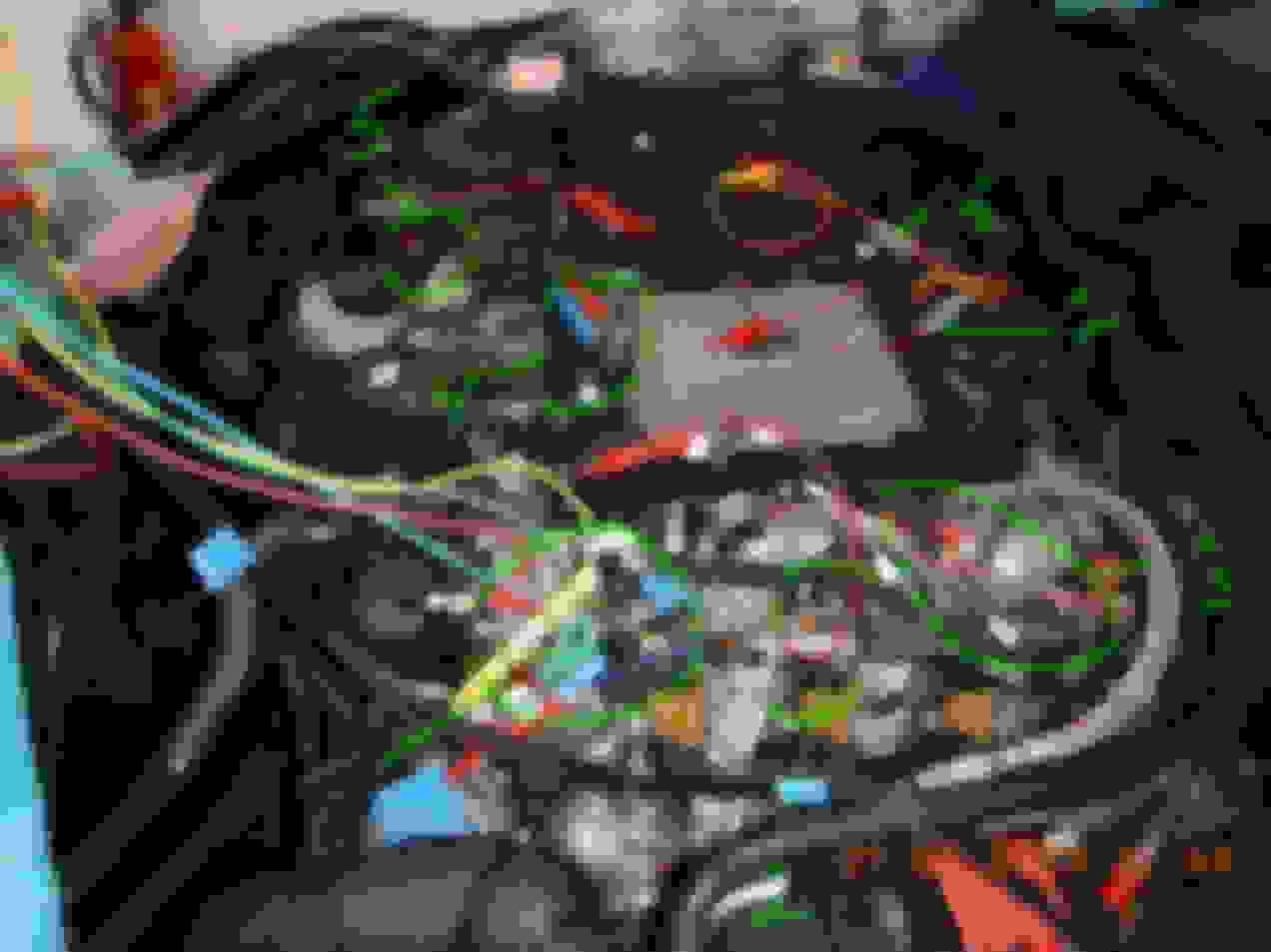
I do not have all connectors of engine sensors rigged as test wire kit yet, but I already have the important ones.
The diagnostic signals : Air pressure sensor at air intake filter Bank 2 called B28/4, wire test kit is number 3 above. Its signal is below
Car been engine OFF since 12+ hours ago. I wake up ECM using lock or un-lock of doors. In few seconds if I do not enter the car, ECM sleep again.
ZOOMED : So ECM sent out this signal pulses per approx 10 millisecond, so in 1 second 100 of these test signals sent out.
If un-zoomed a bit, the signal look like below :
Out of 7 test wire kit I have, 5 are intervention type which means I can disconnect any pins/wire, the other 2 is for sensing only, like I tap or splice into the signal but can not do disconnection.
The 2 of tap type is the Crankshaft Position Sensor and the High Pressure Fuel Pump Quantity valve. I place ready to access connectors for them because they are not accessible without lots of work.
I can't even probe these two sensors at the back side of its connectors , so I have soldered permanently a tap/splice at wire harness and place a connector there item 6 and 7 on 1st image.
I do not like to probe at ECM 2 big connectors, made me headache looking at such small holes
I cover it here : https://mbworld.org/forums/e-class-w...eparation.html
Unique finding is that : Injectors and COP coil-on-plug will not produce any DTC even when ALL of the wires are disconnected when in ECM awake state but engine is not running.
In fact specific to injectors, the ECM during a wake-up state (engine OFF) , does not even send diagnostic signal to injectors, unlike COP which still get diagnostic signals.
COP diagnostic signals. ECM awake by door lock and un-lock, engine is OFF.
The DTC seen using Xentry without engine needed to be running, simply I un-plug pin 1 of all these sensors and run a scan.
==========
The most unique diagnostic signals so far is the Y94 HP Fuel Pump Fuel Quantity Valve
I have to keep database of all these waveform capture while my engine/ECM/sensors are still healthy as a KNOWN-GOOD waveform. It will come handy when my car ages .
Here is a list of summary of the sensors/devices waveforms..
Note : Injectors do not get diagnostic signal from ECM.
=======
This test also good for me to know in depth that my ECM and surely also M276 3.5NA engine ECM, has 2 of 5V sensors power supply. ECM connector M pin 19 and pin 17.
This 5V power supply if it fail due to short on the wire to 1 sensor, all the sensors on this shared path will go banana and Christmas tree lights on your dash.
If one observe in detail, we can see how MB engineers uses different voltage levels and waveforms shape to identify which sensors it belongs too upon successful "ping" return.
I am amazed there is no square waveform used, maybe they do not want the CAN BUS signal to be effected, hence all the waveform are more analog sinewave shape.
Here are 2 of 3 wire type sensors, using the same +5V level but from different +5V supply of the ECM.
MAP sensor and Air Filter pressure sensor
See their different waveform shape and voltage levels.
I hope this information will be useful for those who wants to know how these sensors are able to report its state of wiring health.
This is a great survey, thank you Surya for showing us this ECU information.
Let me try to help you get more trusted actionable results.
We have the same range of issue we saw with COP 4-pins signals:
signal vs. noise
measures referenced to open GND
AC signal or DC voltage
results vs. expectations
Help dump noise
Scope GND!
Let's concentrate on getting valid numbers for the first sensor circuit then reproduce for other sensor circuits...
Active signal A vs. insignificant noise B
Noise is insignificant because we have a much stronger signal event present.
The little 25mV guy does not stand in the scale of 12Volt signal, it's near durt GND floor, signal dust.
We always want to look at noise to rank it's size as significant or unsignificant. A scope is a great tool for us to investigate nasty noise sources... (COP, 3Phase pump!)
identical noise on all inputs...
> What circuit are we lookin at:
We have an old-fashioned 5V static DC reference with its signal-GND and the sensor Output signal.
This sounds super basic but beware the sensor module itself can be more advanced than a simple trim-potentiometer. The output can be driven by a transistor. This is the case for accelerator pedal.
A 5V circuit is normally kept clean for reference. No module is going to introduce chopy noise waves in the shared reference line.
> Test setup :
ONE channel for 5V Ref. input
SECOND channel for sensor OUTPUT
The scope itself references GND at sensor.
You have to have proper GND else all measures are floating unreferenced.
> Expectations:
This is a sensor 5VDC reference circuit,
Its output is a fraction of input voltage
meaning output is a DC voltage as well.
- So definitely no significant waveform here, true
> Help dump noise :
-- This is where the scope becomes paramount !
When you can identify a significant noise, you can try to fix it and scope the results afterwards.
-- SNR is the percentage relation between active signal vs. the noise floor.
-- The "Noise floor" is the level at which the noise is active. When it's low, its unsignificant. When its half the signal it's bad news usually harness crosstalk.
-- Hunting/fixing system noise is not the topic. Here we are dealing with noisy measurements - How do I know... GND does not appear noisy because our measurements float with it. GND is the ultimate clean by definition.
> Hands-ON GND :
So far what keeps screwing your scope sessions is improper grounding.
Lets get troubles out of the way:
- Do not ever double ground!!! (Bang!)
- Only one single GND that you select for your test purpose.
- You need your scope GND NOT REFERENCED TO 110/200VAC, then you can connect your scope GND to ONE single point that becomes your scope reference GND.
- Here it's the sensor Signal-GND, not at Chassis-W10.
There is a difference between Chassis-W10 and sensor GND and that difference you don't want to deal with at all (is a noise source! Hence ECU brings its own clean Signal-GND to sensor).
I hope these tips help your scope practice for good results.
Next time you get wicked results you'll be able to figure out the cause: Faulty car circuit vs. bad test measure.
Last edited by CaliBenzDriver; Jun 22, 2023 at 06:55 PM.
All measurements for this test , except when for injectors , the scope grounds of all channels goes to W10 stud.
My Pico 4425A automotive is a "floating ground" model up to 30V, explanation is here : https://www.picoauto.com/library/tra...loating-inputs
This way I can see activities in any wires of the sensors at all channels in one go, without needing to see wiring diagram in detail for which one is a dedicated signal ground into ECM and not short-circuit anything on our 12V system.
After all this is a simple baseline test to see the diagnostic signals when ECM is awake and not an engine running operational signal, if indeed I was doing troubleshooting.
Great, you have a floating ground scope. You are familiar with floating reference from the link you sent I got this: floating cuts both ways
You do have to know what you are scoping to make a valid measurement that's useful. You must use the proper reference relevant to the circuit. Across floating reference you only get unreferenced junk noise
scoping of a 5VDC Ref.
When you get that sort of spikes on a clean 5v signal... question the trst.
The 5V sensor is using a floating GND circuit from the ECU but because you choose to reference your scope GND in the wrong place, you see mud.
DVM or Scope :
Imagine you are using a simple DVM, if you connect black lead to W10-Chassis: you'll reproduce the same bad reference issue.
This has everything to do with understanding the circuit the live signal and how to use measuring tools.
Scope FUSE with floating GND input:
Essentially you super scope inputs have individual reference inputs (GND). As explained in the picture above: "capacitive coupling".
An application of that feature would be to scope accoss multiple fuses. You can have both sides of fuses connected to scope inputs without connecting to battery GND.
Last edited by CaliBenzDriver; Jun 23, 2023 at 05:08 AM.
DVM instead of scope...
To measure DCV, any multimeter is 100% good enough.
connected..../....
No, not when you want to see the waveform.
Try using the DMM to see the ECM diagnostic signal waveform A & B, probably nothing is showing on the DMM except the flat line 4.3 volt at C
Don't you see how unique the waveform/signal is, first pulse is high (A) and then second pulse is low (B ).
For below red channel, DMM will show zero volts and not the +0.7 to -0.8V , it wont register D and E signal. DMM cant see 10 milliseconds waveform. Usually maximum is 20Hz or 50 millisecond for a DMM.
I am trying too see what is ECM transmitting out, what unique waveform shape and voltage each and every different sensors get , to know the working of my ECM better.
I am collecting a KNOWN-GOOD samples my man, this is what one must do when owning a scope, practice and work on a known-good waveform and keep the database.
Hoping it will be useful someday when and if ( touch wood ) my ECM goes banana in a way not a total signal lost to sensors, but ECM generating weird ones and deemed sensor as a fail but sensor did not fail...who knows.
Surya, I want to help you measure what you need to build your archive with valid measurements.
You believe the ECU is transmiting signals over GND lines... it's only JUNK NOISE acquired because you are hooked up across distinct power/signal GND.
Junk noise over unreferenced GND
It's just an analog DC circuit.
It has no digital waveform signal... NONE!
It's also unlikely to carry any significant noise .
Scope is not magic :
Try to GND right at sensor to loose the unnecessary noise and measure the flat DC with a DVM or use a scope to see that DC is flat, unlike AC waves.
noise at 1st glance
It's easy to spot bad noise: its present on all input test leads
Isn't that easy, yes?
Last edited by CaliBenzDriver; Jun 23, 2023 at 05:52 AM.
Yes, it is analog those sensors I scoped, I am not hoping to see square wave.
Now please help me understand the constant "junk noise" at 100Hz I am seeing, where do you think it comes from and why at 100Hz consistently ?
Signal can be analog too, example knock sensor, its waveform is like a noise.Like a microphone signal out.
You call this noise too ? The triangle waveform and sawtooth ones ? This is HP fuel pump quantity valve which is PWM when in operation.
Yes you got that right: it's clearly just statics & noise. I don't see much value looking at 25mV noise.
What is 25mV in a 12V circuit....
The HPFP proportioning valve is a solenoid just like the VVT coil control solenoids. It works with a coil moving a plunger acting as a valve. The PWM duty cycle precisely sets a depth for the plunger.
You want to go back to the essentials and build up from simplicity. The multi-channels scope has you overwhelmed, one channel per signal is all that's needed for now.
> "TO SCOPE 1 SIGNAL, USE 1 CHANNEL":
This will help you capture meaningful signals. Try the difference, guaranteed!
If you fear "magnetic coil spikes", ok then look at the camshaft hall-effect position sensor. It has no harmful power spikes.
Connect scope channel#1 between A to B...(nothing to Chassis-W10!):👍
> Self-checking:
It's not hard, when all you see is noise then you question why that is:
a bad circuit or a bad measure ??
We all do goofy stuff at times, that why we do self-checks.
Measuring electronics is no different, we do sanity checks.
> Single signal = single channel:
The fancy multi floating channels is a swiss army knife that can do more than you want.
Use what you need to do what you want. Here it's a single signal, clearly a single channel application.
Forget scoping multi channel applications. This is only necessary for synchronous signals with a common trigger - Not here!
Diver down
You've always helped out a lot of good people. I can't let you drawn in the shallows and do nothing.
Hope this helps you well.
Last edited by CaliBenzDriver; Jun 23, 2023 at 08:26 PM.
Mercedes SLR McLaren 722 S Is Extremely Rare Example Modified by McLaren
Slideshow: A one-of-one U.S.-spec Mercedes-Benz SLR McLaren Roadster became even rarer after a factory-backed transformation at McLaren's headquarters.