When you click on links to various merchants on this site and make a purchase, this can result in this site earning a commission. Affiliate programs and affiliations include, but are not limited to, the eBay Partner Network.
I am taking my sweet time to plan for replacement of the engine oil baffle-snorkel and the o-ring : https://mbworld.org/forums/e-class-w...brication.html
The front subframe will need to be removed, that means engine has no place to rest, thus I must "hang" the engine.
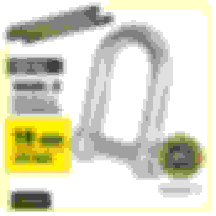
I initially wanted to buy this : and it is actually much cheaper in Indonesia or same price as USA at Amazon for those having Prime Account. Shipping price may be high in USA, not free for even prime member I think
.
...
However, I do not like such a design, because if my engine weight is say 500 lbs to be "hanged", allowing the stand to find support at fender thin metal plate is not acceptable for me.
Like below :
That region is a thin U shape metal and not a true hollow shape single piece bar/tube.
This is what I mean by : allowing the stand to find support at fender thin metal plate is not acceptable for me.
That thin plate at the top part surface is what will carry 500 lbs.
This region is good for compressive mode from below, such as front suspension strut "well" which for my car, front carry approx 1,100 Lbs close to 500KG, driverless at half fuel.
.
I jacked up my car already like easy 50 times or more cycle , using Quick Jack**.
If you guys pay close attention , the front fender will make like some sort of "cracking" sound before tire will lift off completely above ground ( **4 wheels up at the same time )
That sound is what I believe as my plastic fender liner trying to change shape, because now the force applied to the front wheel well region is no more compressive,
but tension. Tension for the total weight of the front strut + whatever is connected to it, trying to "fall" with gravity. Basically this region has flexing occurring during a 4 wheels lift off.
So I thought, what if I buy this kind of engine hoist ?
Well, for engine removal it is OK, but as engine support........ its legs are so long into under the car, I can't work on the engine bottom part or subframe
.
So, what do I do ?
I gave it some brainstorming and I think the best spot to take engine weight load downward is the front suspension top mount itself.
After all there is 500KG / 1,100 LBS of pushing up force there already, so now I want to push it down by 500 lbs approx.
Hence the Engine Support Bar need to be Custom-DIY.
Yes Jeedie, that is possible option, but my ceiling at garage is 4 meters tall.
I think the engine weight + tranny is what I need to calculate. Maybe tranny not a 100% as the tranny mount is still installed, only 2 engine mounts at the front removed.
Liquid weight yada yada, I think 230KG or 500 lbs is decent estimate to be on the safe side.
If I already own a 4 post lift, engine removal table is the best because the car is the one which goes up and not the engine.
Too much $$ and I need a true proper garage for myself if I invest in the above 2.
So, I go the DIY route and support point will be 2 of suspension strut mounts + 1 extra one from the floor as extra option.
I done some angle measurement to figure out the horizon zero degrees challenge.
Testing
The front strut top mount is angled to the rear of the car at 8 degrees down
The front strut top mount is angled towards the engine at 5 degrees down.
I need a pipe/tube as a footing.
I am still in the process of how I can get proper zero degree for the actual support bar. I have a method/hardware in mind, adjustable angle and height. Will update you guys soon.
I use aluminum hollow square bar because I like its lightness also nice looking, no rust.
I will use 2 of those ALU square side by side, it is a 63.5mm x 63.5mm x 3.18mm thickness. So it will be 127mm wide and height 63.5mm.
I done some deflection calculation. As for broken or torn off ALU hollow by shear force.............it wont happen , even at 1,500 lbs it wont happen.
Below is when I use a double hollow square bar material, BUT thickness of a single unit, which is 3.18mm
Below is when I use a double hollow square bar material, and thickness of a single x 2 unit, which is 6.36mm
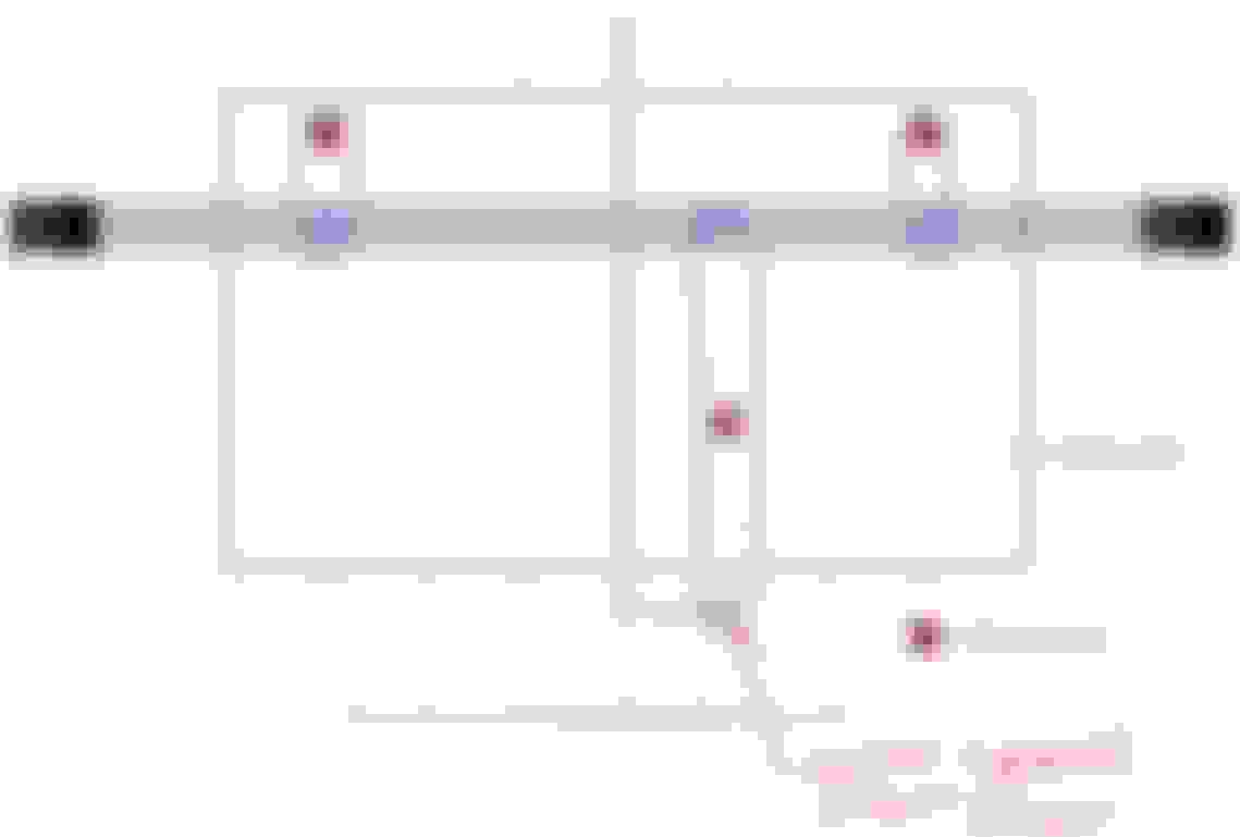
I will need to make a lifting spreader bar, even though I will not lift out the engine.
This is to make sure the engine is fully supported from the top equally.
I do yacht lifting supervision often and spreader bar is a must have. Not only for front and rear balance, but for the fiberglass body not to be squeezed by the lifting belt. We use fabric belt, not metal sling.
Below is a simple example
There are 3 lifting points, of which #2 and #3 are prepared by MB. #1 I must DIY.
I will not use chain with center lifting point, but I will make spreader bar and make sure all lifting points get direct upwards pull, not angled.
I must DIY some sort of lifting plate. So that my noise shield for HPFP will not get damaged.
The lifting plate must be away from that metal bracket by 5CM and use a straight pull up, it will be safe for my HP pump noise shield.
That dumb-azz bolt used by MB is a M7, damn, that is a VERY VERY uncommon size. I used a 6mm ( M6) with paper tape to make it fat ...LOL
I am still brainstorming on the spreader bar.
My intention is to use the same 6.35mm square ALU hollow bar as a spreader bar, sort of.
So the gray is the 2 x hollow ALU square bar and the blue hand ugly sketch is a single ALU square hollow bar, bolted down to 2 x hollow ALU square bar
Its like below unit . but mine has more extension arms , as though as spreader bars...
I must make 2 version of the support for the bar at the front strut.
Version 1 is what I have discussed.
Version 2 is for when I need to remove front subframe completely, which means CAMBER and CASTER arm will have no installation place, aka the front Mcpherson strut is then
have to be removed..... and I loose Version 1 function.
I must make another plate like how one does a front suspension strut stabilizer-stifener brace set up. Where the metal of the suspension well OF THE CAR itself is the one taking load. DUGGH !!!!!
I will jack up the car tomorrow and do a proper survey. For today, I am 80% certain the subframe does not need to be removed for the oil baffle + o-ring replacement at the crankcase
.
.
Electric Power Steering must be removed for sure..............
We have used the engine support in conjunction with a 2 post lift on many w204 chassis, I would expect no different for w212.
We have only lifted the engine enough to remove subframe / other items. Since you have a rwd you have significantly more access through that version of the subframe as opposed to 4MATIC models.
I just saw someone using the engine support bar on a 4 matic , for subrame removal...but he is short by approx 15cm to get his best position.
.
.
I believe the model in use by Maic-SD is this one https://otctools.com/products/engine-support-bar
57" is 145cm and that is too short for equal position L and R of the video, I can only see the R side but not the L side. Need a 160cm long bar if at that location, I just measured it on my car.
I will proceed with my DIY unit, as all raw materials are already purchased. I only need machining by a machine shop.
Also this will be fun
Me sometimes take work so easy and slow and it could be many days that my engine support bar will work at a time,
so getting a better/tougher loading zone for 125KG estimated per side of the car by the support bar will be a bonus.
.
Proof of concept, for the adjustable angle support
Will figure out the locking system for the support later.
====
The rod end is from IKO Japan. PHS10 size/model. In USA this stuff is called HEIM, a brand actually
Having for of these, even a 1,000 lbs is easy duty.
The long bolt in use is 8.8 steel.
I will not be using that round pipe as interface support to the strut top mount.
Change of plan. I have something in mind easier to shape and will be gentle to the strut top mount itself.
I think you are worrying too much about car supporting the engine load using the cross engine support.
You did calcs based on static loading but you forgot dynamic loading as accel and decel forces from strut are way more then dead weight of car.
The car's structure around the strut mount are probably the strongest area on thse side and all boxed in around fender so any load you transfer from inside hood lip ends up going down thru all that sheet metal to where ever you support car be it wheels or jack stands.
Mechanics use these all the time when working on front cross-members or have to remove an oil pan - easy way to lift engine a bit and create space under without having to remove engine.
Engine is light compared to car suspension loading.
If you are worried then use 2 of the cross supports one in front of engine one in rear.
Thanks .....
But I am enjoying myself making a BETTER version of engine support bar and MUCH more expensive than a store bought one. Mechanics use them all the time does not mean they care for their customer's fender thin sheet metal like I do, because they do not own the car they work on.
Now, some idiots made these out of aluminum or metal..........
Some dumb azz seller make them out of rubber...LOL
I custom made them from Nylon PA6, so that it can deform at the round base accepting the most "garbage" 4 post pad , while maintaining its top rectangular insert true to MB pad adapter receiver side.
I will give you samples how abused my custom jack adapter has gone thru.
======================================
After 5 years of abuse
I love Nylon PA6. It can take 10,000 psi easy and can go back to its original shape.
Please do not compare your care level for your car to how I care for my car, not trying to offend you in any way....... but we are probably very different.
No one will give more care and love to your car than yourself....assuming you "maintain" your car to a high standard.
It is not always about fluid changes and yada yada yada, jacking up a car is also an important part of maintenance.
Some people believed jacking up rear portion of the car at a rear DIFF is OK, I don't. I jack up complete rear end with 2 jacks at rear pads.
So now I divert my attention on how to spread engine weight load as least offensive as possible for my car, for an engine support bar scenario.
I agree if you think I am overly worried ......., because I do.
On a side note :
Now, my advice to you, tear down your rear subframe and replace the 2 bushes at the wheel carrier/knuckle,
replace the bushing for the spring control arm at subframe side
replace the camber arms, at least camber arms, both side This should solve your inner rear tires being worn out so fast which unfortunately your car suffered that since day 1 brand new.
MB not able to sort it out during its warranty period is a sad and disgusting, but....... if I were you I will do it myself.
In fact next year I will do those I mentioned and all the bushings of subframe because I want creme la de creme comfort and state of health of my chassis system.
Yup the prof in machine design were adamant about making designs simple and least number of parts to reduce costs and maintenance etc.
Then career in offshore oil exploration they tend to want things simple, so they work longer, less likely to fail, and easier to repair, and parts more likely in stock.
time is big money offshore if they are not drilling.
Kinda the opposite of German engineering where the most complex is the way they design.
One thing I admire about MB is their jack support base plate and wheel alignment holes on their OE wheels.
This means no need to look at stupid user manual for proper jacking points, all 4 at the side and one more at the front subframe for my RWD car.
BMW has the same jack support base plate too.
All of the Toyota-s I owned and my 2010 Ford Fiesta, has no jack support base plate at all.
Believe it or not I did a little dent on my light weight 2010 Ford Fiesta underside because I place a jack WRONG....duggh.
It was the one near the front tire.
I hate Toyota or Ford type underside where they have this metal joint, I do not know the technical name of it........see below :
Above is Ford Fiesta 2010
So we need a jack adapter like this one below
And then the Ford Fiesta jack itself is like this :
My family1980 ish S-Class was this model of jack support base at the car
===
So the jack itself is unique
===
Respect to MB for having all these fixed well engineered jacking or lifting points.
Not only it is least offensive to the car chassis, it is as safe as it can get.
On yachts, when I do lifting up, we have the sling belt locations MARKED too, it is a must, because the designers have done the calculation for equal weight and the location
of the stringers ( Stringers are longitudinal forms that are laid in line with the keel to add extra strength and structural support to the boat. )
Above is not yet a full stringers, the vertical ones not installed yet
=======
Not many people know about MB special 5 holes on its OE rim for alignment use.
Why would MB need to do this ?
Because this is the proper way, as the alignment tool then read the bearing hub and not the rim/wheel which may get bent and distort the reading.
This is typical wheel clamp type alignment sensor/reflector
So those are the attention to details MB engineers do and I respect that.
The Bank 1 has no lifting eye.
I finally have a simple solution.
.
This project is interesting, now I know a little about wire rope rigging, the DO and DON'T and the industry uses quite a good 5:1 safety factor.
I am using 4mm ( 0.158" ) 304 SS wire, the biggest OD that damn hole can fit.
I am allowed Working Load Limit at 185KG ( 407 lbs ), albeit its breaking strength is 827KG ( 2,039 lbs )
There is also a proper technique to clip the wire using different type of wire clips. \\
.
The Bank 2 rear and front is easy. They have lifting ring.
So I use these..........
Lowest rating component at 230KG ( 506 lbs ) WLL ( working load limit ). Must be the M10 thread ( M10 is 5/16" ) . The female hex I used, would qualify the same 230KG WLL
So 2 of 230KG and 1 of 185kg = 645 KG ( 1,419 lbs ) WLL. Well pass my target WLL of 250kg ( 550 lbs )
I am still waiting for another 50mm wide x 20mm height x 4mm thickness ALU hollow bar for Bank 1 .
This one :
This hollow bar will only need to be 7cm (2.76" ) from main support bar, towards firewall.
=================================
The load plate on the suspension top mount is a 15mm (0.59") Nylon PA6.
.
I am still waiting for the machine shop milling work, making my bearing/load pad for the M10 bolt on the 2 ball end. It will be also Nylon PA6
Bearing/load pad for the M10 bolt
Temporary setting
I tested today tightening the two long bolts at approx 40 newton, awesome result
The support bar set is very firm and balanced under tension.
Will update again soon when all done.........................
Yipeeee !!!! DONE and I am a very happy man.with the result.
If only I have machining & aluminum welding assets and skill...... it will be much faster to complete and can make custom parts with some beauty.
.
I have added engine rise height gauge/rod if I can call that.
For number 3, that gauge will also read the deflection of the ALU hollow pipe.
This is as far as I need to raise the engine. Only like 12 - 15mm or 1/2 inch. This means the engine is already "floating" on the DIY support bar.
.
Measurement point, as near as possible to both L & R engine mounts for #1 and #2.
.
.
Below :This is how high the engine mount get "lifted" up, when those engine height gauges/rod rise 12-15mm.
Sorry, no LEFT side engine mount ptoto/video, too tight a space, cant squeeze my GoPro camera in there.
,
I added bearings for all 3 spin-to-lift bolt-nut which is M10 size.
This is a thrust bearing for such purpose. By SKF Germany. Its so nice to spin now, no friction from washer
DIY pressure plate movement limiter, a 10mm Nylon PA6 .... so that that 6.35mm thick ALU will stay on track properly and spread the load well.
I can't bend ALU, not only I do not have such bending tool, ALU does not like being bent. Adding heat will ruin its strength.
.
I added Nylon PA6 as bearing and load spreader pad. 10mm bolt I use has small circumference, it will produce very tight pressure spot on the hollow ALU bars.
Only the RIGHT side get position locked for the Nylon PA6 and the ALU hollow bar, the LEFT side is on purpose not locked because at 250KG load the ALU hollow bars would
bend by approx 19mm. So one side must be free to "move", only one side get locked.
.
RIGHT SIDE LOCKED. ABOVE
.
BELOW : Left side is not "locked". When the calculated bending limit of the ALU hollow bars is reached approx 19mm deflection, that aluminum tape will give way, but the
Nylon PA6 bearing-load pad will slide nicely, it can not fall off.
.
I have measure the deflection of the ALU hollow bar at the maximum engine lift-up height , but I can only measure at the RIGHT side.
.
.
1 full 360 degrees of the big dial is 1mm or 0.0039 inch.
I think in the exact middle length of the ALU hollow bar, the deflection would be double or approx 5mm or .0.196inch
That is what I saw from civil engineer calculation of the such deflection.
.
My final touch-up would be custom-made a spinning handle like below :
TSB 01
Technical Screw-Up Bulletin
Need to modify Bank 1 wire rope securing method.
That "hole" has a bit of gap which if pulled maybe 200kg / 440 lbs, the wire rope may slip out.
Result of yesterday's long test.
The wire rope got so squeezed....
Below is how that plate mates with cylinder head
======
Now I made something like a spreader bar to make sure wire rope aim for those holes and no where else and also no more chance wire rope to slip out
This Nylon PA6 "spreader bar" will survive well in compression mode. It is so dense and hard.
 10-18-2023, 09:43 AM


 also nice looking, no rust.


 , because I do.
 , but....... if I were you I will do it myself.


 with the result.