When you click on links to various merchants on this site and make a purchase, this can result in this site earning a commission. Affiliate programs and affiliations include, but are not limited to, the eBay Partner Network.
The W212 E250 Engine Control Unit ECU is Mercedes part number 274 900 09 00
and was removed from M274 2 litre petrol turbo engine
With the screws removed from the cover it is impossible to lift the cover off the heatsink
because they used a tube of silicone instead of a round rubber seal between the two.
You need to work around the cover numerous times and prise it up and wedge it bit by bit to get it free
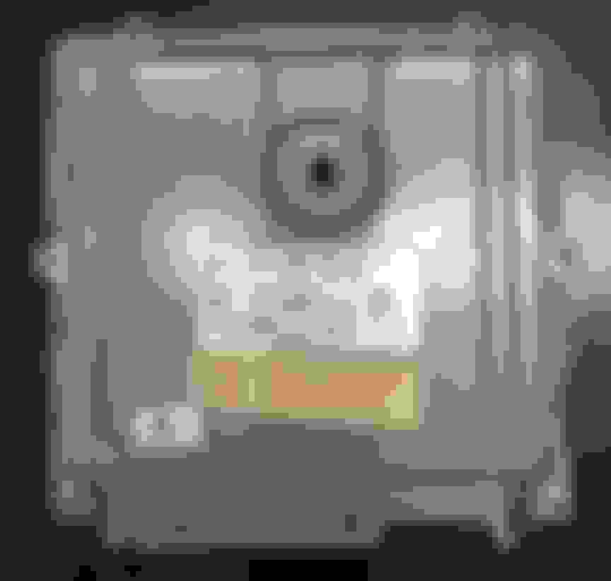
The black button on the lid is a breather and you do not need to remove it
The circuit board is fixed to the heatsink by two screws on the connectors and one screw in the middle
They used silicone rubber between the board and the heatsink to transfer the heat from the components on top of the board
The circuit board is stuck tight and cannot be lifted out.
You need to work from a corner lifting it up carefully so as to not crack the board and work around it over and over bit by bit.
The connectors are stuck down by silicone, and being soldered to the board by the leads, makes it difficult to free the board because of that silicone holding the connectors down
I reworked the solder joints on the electrolytic capacitors
I carefully cleaned any solder flux from the board with flux remover and toothbrush
I cleaned all the silicone off the cover and heatsink which was very time consuming
The cover seems to be designed to have a 3mm rubber seal fitted all around but not manufactured with one
Part of the seal needs to be fitted to the heatsink and most of it to the cover.
The seal I used is Moroday 3mm rubber round EPDM sponge in a 5 metre length part number 2-57001A
I used Selleys Fix and Go Supa Glue which sets in 10 seconds.
Apply a bit along the channel and seat the rubber seal in it bit by bit.
Do a straight run, let it set, then do the corner bit, etc.
Start and finish at the bottom so that the seal is unbroken at the top
For the seal on the heatsink overlap each end a little.
When you prise the lid off you may bend the lip a bit,
so make sure it fits back on the heatsink properly before final reassembly
Screw the circuit board back on with the three screws and make sure the connectors bed down on the rubber seal
Now screw the cover down tight to make the seal with the rubber, and also to pinch the flange of the lid down on the circuit board
It is time consuming because they used silicone to seal it.
You need time to get it apart carefully and then clean up the silicone mess
Allow a full day to take care in the work because it's the engine's brains and nothing will work if damaged.
As you see, in mine there is engine oil on the earth strip top left, on the circuit board.
There was engine oil in the ECU connectors when I removed the plugs.
Engine oil had seeped through the connector pins and got inside the ECU.
The connector pins had oil around them on the body of the connector inside the ECU which was the clue.
Occasionally I would get a malfunction message in the instrument cluster
Some person who did an oil change before the car became mine was not careful and had dumped oil on the ECU connectors
A good result and I cleared the fault. You need to be extremely careful in disassembly of the ECU.
Last edited by Bruce Hubbard; Dec 12, 2023 at 04:37 AM.
Nice electronics - Thank God, no solderless pins are used on this E250 ECU: good
FYI, nobody poured oil in the connector while doing oil service.
What you are seeing is called "oil-in-harness" it's the infamous $10k repair tab including replacement of a piece of engine loom.
Actually oil is known to routinely come out of over heated cam sensors. Some engines M276/8/(4?) are thought to have limited cylinder head lubrication as source of extreme heat.
Eagle eye was happy looking at all this when I spoted some'... solder side
what does that look like ...
That right there is a failed solder joint
What does that mean ?
80% chance it's got more friends laying around nearby.
I don't make this stuff up.... they do!!!
Changing the cap is the best thing to do while cover is popped open - They are all 3 legged special caps where consumer caps only have 2 pins. I guess this is automotive with extended specs to work right over exhaust pipes or engine crown, the hottest spots in engine bay
Last edited by CaliBenzDriver; Dec 12, 2023 at 05:54 AM.
A coil over ferrite is called a choke.
It stops nasty current spikes from crossing through enter or exit.
It has all the reasons to fails:
the fat wire section dissipates soldering heat
the heavy body vibrates because it was not glued!
the currents have high spikes that stress weaks joints
At least it needs to be glued down seriously same is true for caps as well - Vibration harmonics are known solder killers !!!
13 candidates for siliconed glued
You have:
the 6 stuby electro caps
the 7 choke ferrites
✌️
Last edited by CaliBenzDriver; Dec 12, 2023 at 03:14 AM.
The boards are as seen when disassembled
before the solder joints were inspected and reworked
Very pleased to see some readers here with good electronics skills
Nearly 40 years ago I used to fix railroad electronic controls certified for 1 million Miles.... vibration were taken seriously.
That's how I pick at this easily to help you out.
++++ everything was virtually glued down by generous application of conformal coating.
Last edited by CaliBenzDriver; Dec 12, 2023 at 04:37 AM.
The W212 E250 Engine Control Unit ECU is Mercedes part number 274 900 09 00
and was removed from M274 2 litre petrol turbo engine
With the screws removed from the cover it is impossible to lift the cover off the heatsink
because they used a tube of silicone instead of a round rubber seal between the two.
You need to work around the cover numerous times and prise it up and wedge it bit by bit to get it free
The black button on the lid is a breather and you do not need to remove it
The circuit board is fixed to the heatsink by two screws on the connectors and one screw in the middle
They used silicone rubber between the board and the heatsink to transfer the heat from the components on top of the board
The circuit board is stuck tight and cannot be lifted out.
You need to work from a corner lifting it up carefully so as to not crack the board and work around it over and over bit by bit.
The connectors are stuck down by silicone, and being soldered to the board by the leads, makes it difficult to free the board because of that silicone holding the connectors down
I reworked the solder joints on the electrolytic capacitors
I carefully cleaned any solder flux from the board with flux remover and toothbrush
I cleaned all the silicone off the cover and heatsink which was very time consuming
The cover seems to be designed to have a 3mm rubber seal fitted all around but not manufactured with one
Part of the seal needs to be fitted to the heatsink and most of it to the cover.
The seal I used is Moroday 3mm rubber round EPDM sponge in a 5 metre length part number 2-57001A
I used Selleys Fix and Go Supa Glue which sets in 10 seconds.
Apply a bit along the channel and seat the rubber seal in it bit by bit.
Do a straight run, let it set, then do the corner bit, etc.
Start and finish at the bottom so that the seal is unbroken at the top
For the seal on the heatsink overlap each end a little.
When you prise the lid off you may bend the lip a bit,
so make sure it fits back on the heatsink properly before final reassembly
Screw the circuit board back on with the three screws and make sure the connectors bed down on the rubber seal
Now screw the cover down tight to make the seal with the rubber, and also to pinch the flange of the lid down on the circuit board
It is time consuming because they used silicone to seal it.
You need time to get it apart carefully and then clean up the silicone mess
Allow a full day to take care in the work because it's the engine's brains and nothing will work if damaged.
As you see, in mine there is engine oil on the earth strip top left, on the circuit board.
There was engine oil in the ECU connectors when I removed the plugs.
Engine oil had seeped through the connector pins and got inside the ECU.
The connector pins had oil around them on the body of the connector inside the ECU which was the clue.
Occasionally I would get a malfunction message in the instrument cluster
Some person who did an oil change before the car became mine was not careful and had dumped oil on the ECU connectors
A good result and I cleared the fault. You need to be extremely careful in disassembly of the ECU.
heatsink heat spreaders
Bruce I'm wondering what kind of heatsink compound did you use to bridge the gap between heatsink-case evenly ?
It's not often around here we get to peek at the hardware inside one of these great modules.
The fancy firmware functions we've come to know are made possible by this nicely rugged advanced hardware.
We know engine control is all about DATA + TIMINGS to workout every single device: injectors, spark coils, fuel pumps, Tstat, ....
Above the device layer is an overall controller that computes maps for Ignition Timing advance, Fuel Trims, target cooling, VVT Timings, ....
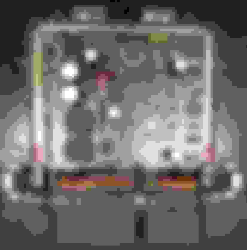
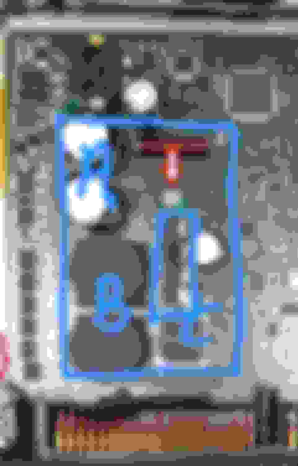
These sort of blick architecture is directly reflected by the board component design as follows.
Networked uControllers team of 3 or 5pcs
These microcontrollers run efficient small instruction set to manage a few specific devices in real time.
Big boss is a TriCore CPU by Infineon !!
This is where the main high level code runs to manage overall data flow in and out of the engine control over CAN-C.
voltage multiplier
Here we spot (coils + caps + diodes) plus a uController and a cleanup chocke.
Output MOSFET drivers
These automotive power drivers switch tough currents into ignition coils and injectors in the best way imaginable. Multiple super fast burst controlled by a low power 3VDC chip !!
cleaned up ASIC control
We see an analog power supply and an output controller. I don't know what single analog function this chip is serving... possibly a quad driver ASIC
Architecture of building blocks to create solutions
When Bosch builds these ECU modules it's to best showcase what German technology can produce at a given time. This is then pushed onto Denso Japanese and Hyundai Korean partners to design their own products with the same proven stock.
Great designs need great testing that's what Germans cars are for. Develop sofisticated systems with outstanding performance and the right amount of saltiness to bring them down on cue.
> POWER TIPS:
If you like to preserve your fancy electronics then rework the stressors carefully built into this chassis - In that order :
-- Fix the nastyamazing main GND strap
-- Keep AGM charged up to smooth out ripples
-- Clean marginal GND posts, all of VIP's
-- Cancel the solderless pin surge sources
These steps will simply eliminate uncontrolled surge spikes initiated by the restless 100A fan.
Voltage spikes are used to foster CAN chaos of modules supplied by poor power. This is very much like our VVT on low oil. The good performance are easily turned around either way.
Tips courtesy of CALI with many-many thanks to Master @S-Prihadi leadership, good friends... and MBWorld forum - Danke.
+++++ RELATIONSHIPS...
What is the correlation between poor connections and damages ?? IT IS VOLTAGE SURGE SPIKES.
A poor connection is an inline resistance that drops voltage under load. When voltage drops current naturally goes right up to carry the load power.
Under sized circuits with overrated current is a recipe for overheating oxidation troubles. This happens every where bad resistive connections are found: relays, contacts, solderless, painted GND.
The alternator manages the voltage output based on ECU request but it can not react to load spikes. The voltage regulation is averaged out correctly but sharp spikes are created by main strap poor serial connection. On the chassis side of the strap the power appears dirty unless a good battery is available to make up for dynamic demands like a capacitor does to smooth out ripples. Chokes do the same to smooth out currents, not voltage.
The bottom line is you need excellent connections to feed low dynamic impedance to heavy spiky loads: ECU + FAN + TCU solenoids.
Last edited by CaliBenzDriver; Dec 12, 2023 at 08:46 PM.
Reason: Power TIPS + RELATIONSHIPS
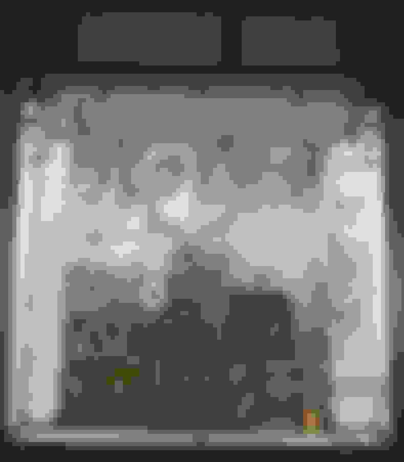
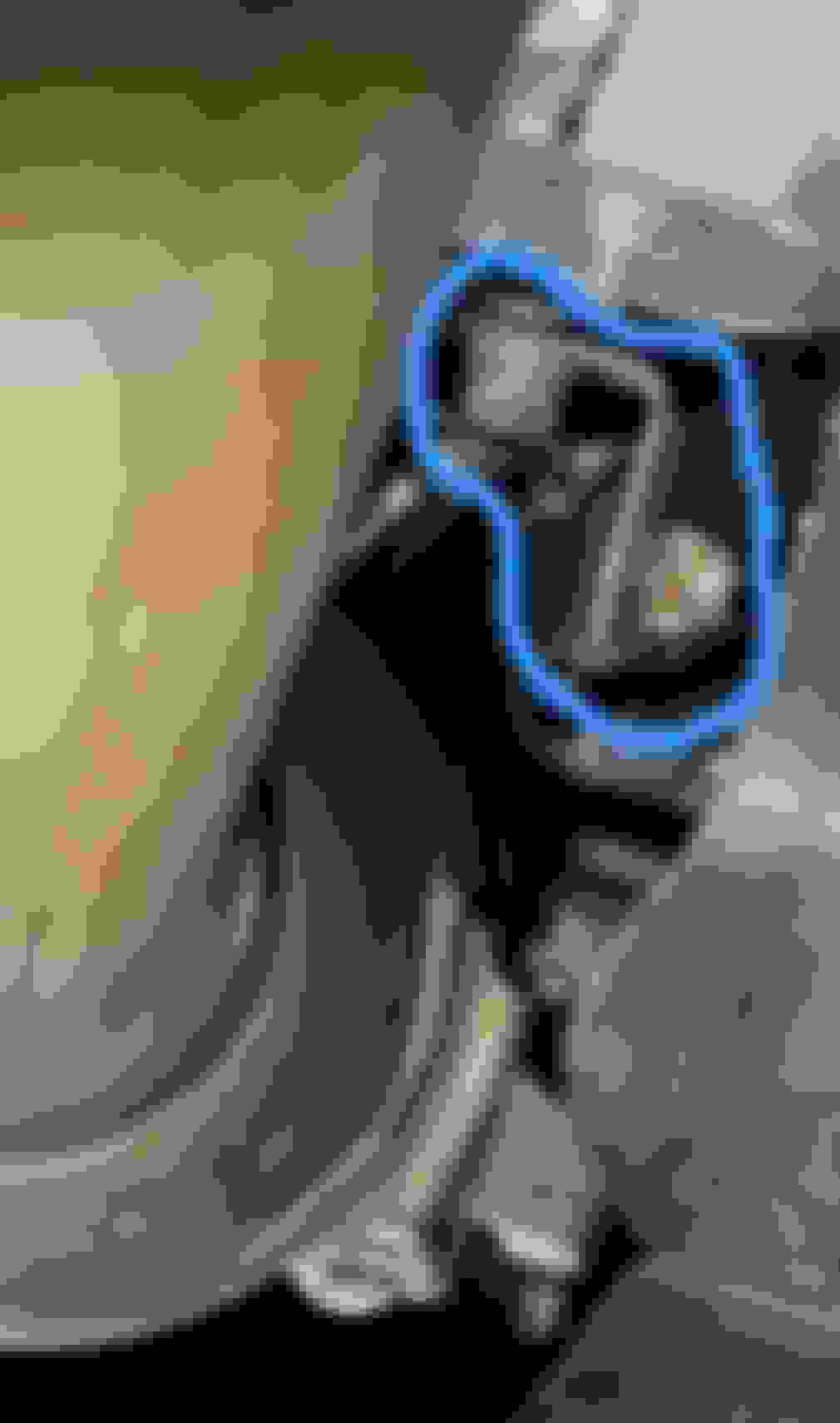
Here is our main connection that feeds power to the whole chassis.
Every module power is referenced through that pretty ESSENTIAL MAIN PATH!
This is important because voltage spikes age/kill capacitors and batteries tasked with smoothing them out. This strap is implemented as a perfect glitches generator.... this shouldn't ignored.
Single GND strap:
Battery is on chassis side
Modules are on AGM side
Alternator is on engine side
Exposed under side... quick repair: amazing! 😂
This connection is as important as the +12V connection on the back of the alternator. The difference is GND can not short out... to GND but it can get poor which to create high resistive drop glitches.
Both soldered + crimped near hot exhaust cat ✌️
Sharp contrast in the use of this great quality component versus where it is used.
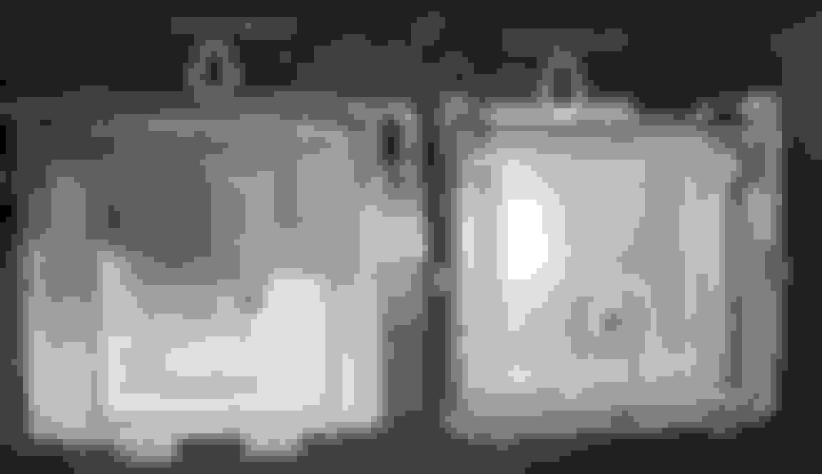
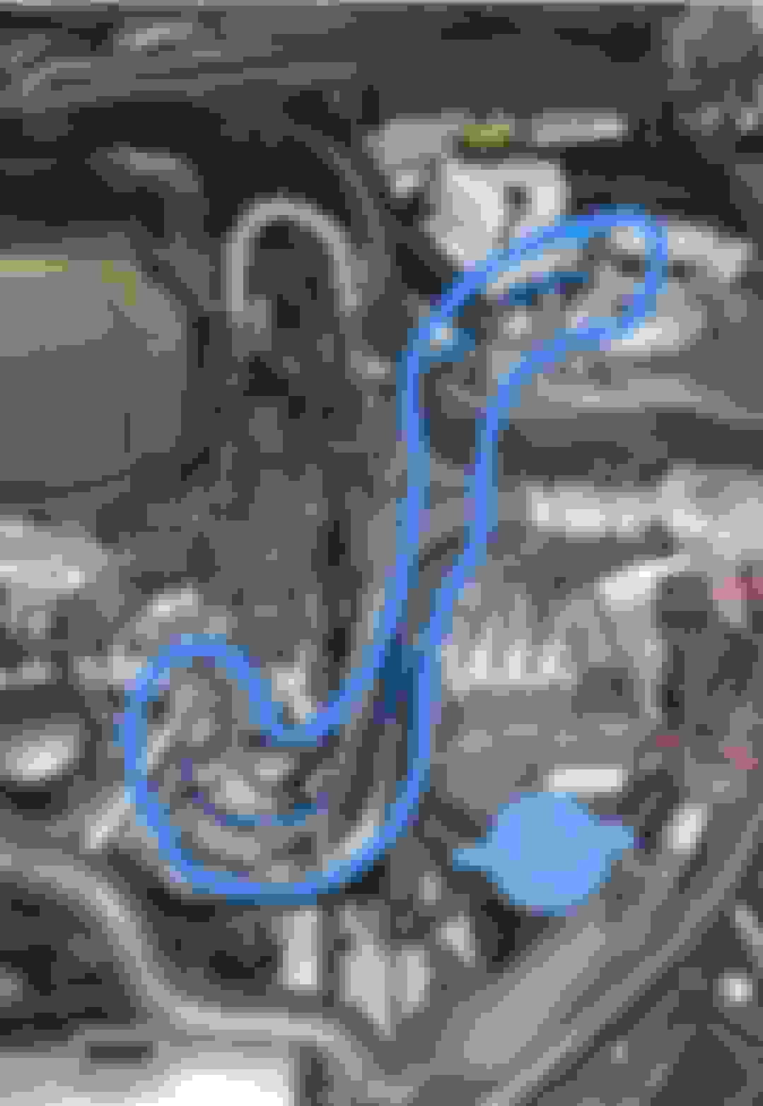
> FIXING:
The best way to cancel this troublemaker is to double it up with a secondary strap high up in a dry location.
my additional main GND
> Quick and dirty:
I don't have a crimping tool for that size wire... all I want is a reliable GND.
Now my starter cranks 40% faster.
That's another thank you MS for pointing it out when you 1st came across it.
Last edited by CaliBenzDriver; Dec 13, 2023 at 08:04 PM.
Got some multi strand welding cable and ends I still have in stock just for this very thing, but the old Snap-on cable crimpers have seen much better days. The torch it is...
Mercedes SLR McLaren 722 S Is Extremely Rare Example Modified by McLaren
Slideshow: A one-of-one U.S.-spec Mercedes-Benz SLR McLaren Roadster became even rarer after a factory-backed transformation at McLaren's headquarters.