


Ongoing Maintenance and Repair for a 2003 S600.

Thread Starter
Senior Member
Joined: Dec 2011
Posts: 401
Likes: 46
From: Ontario, Canada
MB 2003 S600. Volvo 2003 XC70.
Thread Starter
Senior Member
Joined: Dec 2011
Posts: 401
Likes: 46
From: Ontario, Canada
MB 2003 S600. Volvo 2003 XC70.
Performed 150kkm maintenance.
Here is the DIY guideline for what to check other than just engine oil/filter replacement.
I do the maintenance every 10kkm. But if you schedule the maintenance base on the FSS reminder, it will be fine too.
I combine A&B services and check all of them when possible.
Engine
Engine oil and filter replace (Mobil 0W-40)
Check Catch, Hinges, Hood condition
Coolant level check and adjust
Battery check fluid level, charge, and mounting
Auxiliary drive/v-belt check, replace if needed
V-belt, 3 pulleys and tensioner replace (150kkm or 10 years)
Air filter cartridge replace (90 kkm or 4 years)
Spark plugs replace (90 kkm or 5 years)
Fuel filter replace (90 kkm or 5 years)
Coolant replace (240 kkm or 15 years)
Steering and Suspension
Check Ball joints
ABC fluid level
Power steering fluid level check and adjust
ABC & Steering filter & fluid replace (50 kkm)
ABC lines & hoses check, if weeping replace
Transmission, Driveshaft and Defferential
AT fluid level check (Engine on, Trany fluid 80c)
Driveshaft joints check for wear, boots for damage
Automatic transmission fluid replace (60 kkm)
Differential fluid replace (90 kkm)
Check Drive shaft flex disk (80 kkm or 4 years), replace if any damage
Controls and Lighting
Exterior lighting controls check
Washer fluid level check adjust
Check all wiper blades
Body
Doors,hood,trunk,sunroof;lubricate hinges,latches,sliding parts
Body paint and structure check
Wheels and Brakes
Brake pads and rotor check
Brake fluid level check
Parking brake check adjust
Tires wear, damage and condition
Tires check pressure, include spare tire
Brake fluid replace (2 years)
Interior
Warning/Indicator, Illumination and interior lighting
Windshield wiper, washer and headlamp cleaning system
Reset FSS Counter in Instrument Cluster
Check Seat Belt for damage and proper condition
Dust filter clean, replace if needed
Sun roof sliding rail clean and lubricate
Cabin active charcoal air filter replace (90 kkm or 5 years)
Leakage and damage
Fuel & Brake lines, Exhaust, Body Structure & Paint, Steering & Suspension
Last edited by haoz129; May 19, 2014 at 09:58 AM.
Newbie
Joined: Jan 2014
Posts: 1
Likes: 0
2001 S600, 98 SL500, 97 S420, 76 SL380 Roadster 92 500SE
NOTORIOUS S600 MISFIRE CYL 1,2,3
03' s600 Anyone know of a way to increase stop idle without the use of a computer? Currently at 600-650RPM, trying to get it to rest at 700. Why? Unique misfire issue...
All vacuum lines checked good, no fluid arcs or electrical shorts. MAF mass airflow replaced. 24 plugs replaced, coil packs replaced. O2's replaced even though they may have been a symptom of the misfires.
Check this out...
Ignition turned on after OBD2'ing and clearing codes.
If I slighlty keep my foot on the accelerator to maintain >/= 680 RPMs at parked idle and continue to do so while parked at a stop light and don't allow the motor to fall below 675-700RPM's I never experience any trouble codes or misfires. The car runs absolutely perfectly, all day long.
I'd rather not have to replace the acceleration adjustment module behind the air intake assy - the kit comes with a new accelerator pedal... Unless I have to.
If I can manually increase the RPM's just a tad higher, I'm good to go to Marta for emission testing. Live OBD feedback has shown me that when the engine's idle falls below 680RPM, the Check Engine Light appears.
Everyone wants to blame it on a leaky vacuum. I've sprayed soapy water on it all.
I've run out of options and go around ideas. Any feedback would be greatly appreciated.
New to the forum. I hope to have posted appropriately.
I must insert this icon...
Thread Starter
Senior Member
Joined: Dec 2011
Posts: 401
Likes: 46
From: Ontario, Canada
MB 2003 S600. Volvo 2003 XC70.
I noticed that the v-belt pulleys and tensioner were running rough a year ago. At that time, I was replacing ABC pulsation damper hose, that is why I removed v-belt and had a chance to check the pulleys and tensioner. I didn't replace them because I got the parts too late. I just removed the seals, clean residual, repack grease for the bearings then put them back. That was around 140kkm.
Now is 150kkm and I decide to replace v-belt, 3 pulleys and the tensioner. Currently all bearings are working well.
I don't see maintenance suggestion from MB about when to replace v-belt and related accessories. I do know Volvo recommends to replace belts at 168kkm or 10 years for my XC70. Now this S600 is 11 years old and it's fair to do it as preventative maintenance.
Because I am lazy so I decide to do it a little bit differently.
The V12 engine bay is known to be packed and leaves no room for working with the fan in place.
Since I have a gift that my hands are small so I tried to do the belt without removing the fan.
The only thing I removed is the coolant pipe on top/front of the engine, in order to maneuver the tensioner out. I worked almost blindly as I couldn't see most of the bolts very well. In such a small space, you need to be a little bit creative to accomplish this task. Check picture 1, see limited space in front of the engine.
Anyway, other than no room to work, just regular stuff:
1, Have paper towel in place and remove coolant pipe on top/front of the engine;
2, Turn tensioner counter clockwise to release tension then remove v-belt;
3, Remove pulley on the tensioner by using T40 torx. This is not necessary if the fan was removed. But it is required when the fan is still in place. There is no room to remove the tensioner as a whole assembly in my case. Check picture 2, see how I sneaked the tensioner out.
4, Remove 3 other pulleys by using T50 torx. See pictrue 3, old parts;
5, Put 2 new smoothed pulleys in place. Torque to 35nm. I got 642 200 10 70, it's updated version which has metal shield in the back making it hard to fit. By tightening the screw, the pulley is pushed into place and you will feel the friction. I was worried that I will over tighten and strip the bolt.
6, Put the grooved pulley in place and torque to 35nm;
7, Put tensioner without pulley on it and torque 2 bolts to 14nm;
8, Put tensioner pulley on and torque to 35nm;
9, Turn tensioner counter clockwise to release tension then route new v-belt into palce, see picture 4 for v-belt layout. Route the belt between pulleys are not easy. Better have another person to help by using a long hard wire to hold the belt in shape;
10, Double check v-belt position then put coolant line back and torque 2 bolts to 8nm;
11, Start engine. Top off coolant or remove air from coolant hose if needed.
Please notice 35nm (for 3 pulleys) is only valid for V12/M275 engine, other engine may have less torque.
Parts and cost: total $260
- v-Belt(014 997 37 92): $32;
- Tensioner(137 200 02 70): $110;
- Grooved pulley(000 202 07 19): $55;
- 2 smoothed pulley(642 200 10 70, replace 137 202 01 19): $63;
Time: 4 hrs.
Last edited by haoz129; May 14, 2014 at 12:29 AM.
Thread Starter
Senior Member
Joined: Dec 2011
Posts: 401
Likes: 46
From: Ontario, Canada
MB 2003 S600. Volvo 2003 XC70.

MBWorld Fanatic!


Joined: Nov 2010
Posts: 2,605
Likes: 343
From: Welwyn, Herts, UK
2006 S600
I found an interesting Hydraulic Systems Manual by Parker today:
http://www.google.co.uk/url?sa=t&rct...69620078,d.ZWU
So with thanks to parker, here are some interesting quotes:
Modern hydraulic equipment is becoming highly precise and as such more sensitive, so as a result the importance of a clean working fluid in the system is growing. Because as many as 75% of hydraulic system failures are caused by contamination of the fluid by solid particles, the initial cleanliness of hydraulic components, as the main source of these contaminates, is vital.
There's an interesting section on temperature as well. It stands to reason that over=-heated hoses fail more quickly, but I haven't seen anything to quantify this. Well, medium and high-pressure hoses are usually rated to working pressure at up to around 100 deg C. There's a non-linear de-rating of max working npressure at higher temperatures, but the short version is that you get 100% working pressure (say 300 bar) at 100 deg C, and that derates down to ZERO by 150 deg C.
I'm not sure what the under-hood temperatures are, but I bet they're usually close to 100 deg C, and often go higher - a lot higher with the V12TT! I reckon that gives all the non-metal parts like hoses, motor mounts and coilpacks a hard time. I found out recently that my S600TT has air-cooled motor mounts - that's what the NACA ducts on the under-tray are for. I never realised that until I dropped the front subframe.
I just removed six ABC hoses from my engine compartment, including the one the goes under the engine, and have a few interesting pictures and observations to make.
Nick
http://www.google.co.uk/url?sa=t&rct...69620078,d.ZWU
So with thanks to parker, here are some interesting quotes:
Excerpt DIN 20066:2002-10:
For the production of hose assemblies the hose (bulk hose) must be younger than 4 years according to the hoses date of manufacture. The service life of a hose assembly, including any period of storage should not exceed 6 years; the period of storage should not exceed 2 of these 6 years.
For the production of hose assemblies the hose (bulk hose) must be younger than 4 years according to the hoses date of manufacture. The service life of a hose assembly, including any period of storage should not exceed 6 years; the period of storage should not exceed 2 of these 6 years.
Additionally, the International Standard Organisation (ISO) has prepared a draft version of a guideline for hose/hose assembly usage that differs slightly from the German guideline. The ISO/TR 17165-2 states that the shelf life of hose as bulk hose or as hose made of 2 or more materials should not exceed ...10 years... from the date of manufacture of the hose if stored in accordance with ISO 2230 (ie: cool, dry, clean, dark)
In general the combination of high temperatures and high pressures reduce the service life of the hose. More regular inspection of the hose assemblies should be carried out to assure the continued safe functionality of the hose assembly.
Modern hydraulic equipment is becoming highly precise and as such more sensitive, so as a result the importance of a clean working fluid in the system is growing. Because as many as 75% of hydraulic system failures are caused by contamination of the fluid by solid particles, the initial cleanliness of hydraulic components, as the main source of these contaminates, is vital.
There's an interesting section on temperature as well. It stands to reason that over=-heated hoses fail more quickly, but I haven't seen anything to quantify this. Well, medium and high-pressure hoses are usually rated to working pressure at up to around 100 deg C. There's a non-linear de-rating of max working npressure at higher temperatures, but the short version is that you get 100% working pressure (say 300 bar) at 100 deg C, and that derates down to ZERO by 150 deg C.
I'm not sure what the under-hood temperatures are, but I bet they're usually close to 100 deg C, and often go higher - a lot higher with the V12TT! I reckon that gives all the non-metal parts like hoses, motor mounts and coilpacks a hard time. I found out recently that my S600TT has air-cooled motor mounts - that's what the NACA ducts on the under-tray are for. I never realised that until I dropped the front subframe.
I just removed six ABC hoses from my engine compartment, including the one the goes under the engine, and have a few interesting pictures and observations to make.
Nick
MB World Stories
The Best of Mercedes & AMG

7 Craziest Things AMG Gas Ever Built
Verdad Gallardo
New Electric Mercedes-AMG GT 4-Door Coupe Unveiled: 10 Things You Need to Know
Verdad Gallardo
6 Mercedes Models That Did NOT Age Well (But Are Somehow Still Cool)
Verdad Gallardo
Manual Mercedes? 6 Times Sindelfingen Let Drivers Have All The Fun
Verdad Gallardo
Mercedes SLR McLaren 722 S Is Extremely Rare Example Modified by McLaren
Verdad Gallardo
8 Classic Boxy Mercedes Designs That Have Aged Like Fine Wine
Verdad Gallardo
Flawlessly Restored Mercedes 190E Evo II Heads to Auction
Verdad Gallardo
Electric Mercedes C-Class Unveiled: 11 Things You Need to Know
Verdad Gallardo
Mercedes EQS Gets A Major Update: Everything You Need to Know
Verdad Gallardo
MBWorld Fanatic!


Joined: Jan 2007
Posts: 3,342
Likes: 11
From: PA
S600, GL450, GLC 43
I found an interesting Hydraulic Systems Manual by Parker today:
http://www.google.co.uk/url?sa=t&rct...69620078,d.ZWU
So with thanks to parker, here are some interesting quotes:
There's an interesting section on temperature as well. It stands to reason that over=-heated hoses fail more quickly, but I haven't seen anything to quantify this. Well, medium and high-pressure hoses are usually rated to working pressure at up to around 100 deg C. There's a non-linear de-rating of max working npressure at higher temperatures, but the short version is that you get 100% working pressure (say 300 bar) at 100 deg C, and that derates down to ZERO by 150 deg C.
I'm not sure what the under-hood temperatures are, but I bet they're usually close to 100 deg C, and often go higher - a lot higher with the V12TT! I reckon that gives all the non-metal parts like hoses, motor mounts and coilpacks a hard time. I found out recently that my S600TT has air-cooled motor mounts - that's what the NACA ducts on the under-tray are for. I never realised that until I dropped the front subframe.
I just removed six ABC hoses from my engine compartment, including the one the goes under the engine, and have a few interesting pictures and observations to make.
Nick
MBWorld Fanatic!
Joined: Nov 2010
Posts: 2,605
Likes: 343
From: Welwyn, Herts, UK
2006 S600
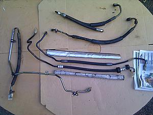
These are the six ABC hoses that I removed from around the engine compartment. I'm zooming in on that area as there are three potential causes of premature hose failure that I'm homing in on:
High working pressure (ie: feed lines, rather than return lines, which never fail)
High ambient temperature (hoses often fail in and around the engine)
Unprotected hoses (MB already protects the hoses in the hottest locations)

The two hoses top right are the pump output and the early type vibration dampener, which both run across the front of the engine.
The two hoses in the middle are the pressure regulator outputs, which run back across behind the engine, where the sway bar used to go.
The pipe on the left is the bogey pipe that goes under the engine, and feeds the pressure regulator.
I cleaned up all the metal pipework and pipe covers, but I left the hoses untouched so I could take these pictures.

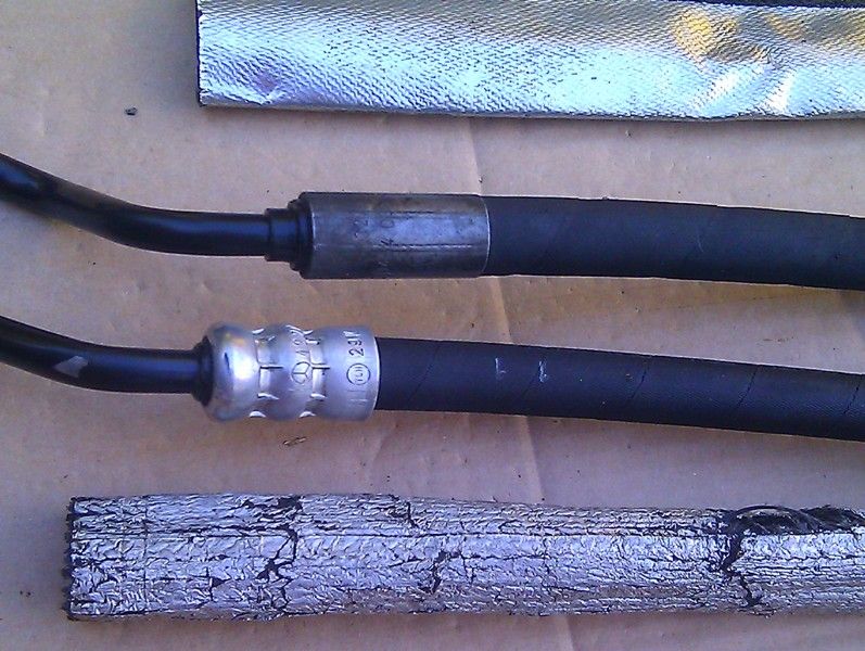
This is a close-up of the two regulator output pipes. I guess they were considered to be vulnerable to hot air exiting the rear of the engine compartment, and they are protected by these aluminised fibreglass sleeves. As you can see, the hoses are in good condition. Since I have a rare opportunity to access everything at the moment, I'm going to replace them as a precaution. This also gives me the opportunity to get some compression connections at the ends of each hose, so they're easy to replace in future (as Mercedes should have done).

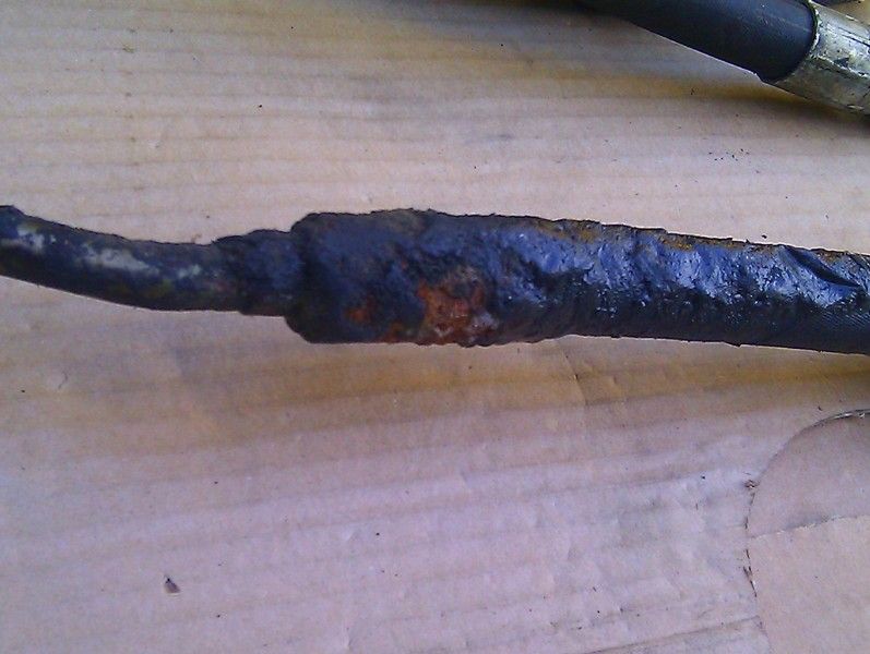
By contrast, this is a close-up of the pump output pipe, which is in profoundly, shocking, condition. This pipe is almost invisible and equally inaccessible, but would you want to drive a car where this was holding it off the ground? Obviously I'm going to replace it, but its a big clue about what makes ABC tick, or more importantly, fail. This pipe is unprotected. It does have a short rubber sheath to give physical protection against abrasion from the subframe and brackets, but there's no heat shield.
I've done a little research, and such heat shields are quite common and inexpensive. They're usually made out of woven fibreglass cloth - either woven into a tube, or sewed into one. They're called fire sleeve / sleeving, thermal insulation, aluminsed shield or braided heat sleeving or similar. Sometimes they're aluminised on the outside, like these, or coated with a robust silicone. All are good for high temperatures.
Its occurred to me recently that its the high pressure / high temperature hoses around the engine that fail most often.
My first thoughts were that all hoses had to be inspected every year, and replaced every five years (rather than simply when they failed).
My focus has turned to the vulnerable hoses close to the engine, that run at high pressure all the time. No need to be so paranoid about the cool or low-pressure hoses.
But given the good condition of those regulator output hoses above, I now think that we simply need to protect all the vulnerable hoses with suitable fire sleeves. I'm going to fit tubular sleeves over all my new pipes, but they can still be wrapped around existing pipes using suitable fastenings. I very much like simple, cheap, robust, solutions to difficult problems, and I think I've just found another one. This is what heat sleeves / fire sleeving normally looks like:


Nick
High working pressure (ie: feed lines, rather than return lines, which never fail)
High ambient temperature (hoses often fail in and around the engine)
Unprotected hoses (MB already protects the hoses in the hottest locations)
The two hoses top right are the pump output and the early type vibration dampener, which both run across the front of the engine.
The two hoses in the middle are the pressure regulator outputs, which run back across behind the engine, where the sway bar used to go.
The pipe on the left is the bogey pipe that goes under the engine, and feeds the pressure regulator.
I cleaned up all the metal pipework and pipe covers, but I left the hoses untouched so I could take these pictures.
This is a close-up of the two regulator output pipes. I guess they were considered to be vulnerable to hot air exiting the rear of the engine compartment, and they are protected by these aluminised fibreglass sleeves. As you can see, the hoses are in good condition. Since I have a rare opportunity to access everything at the moment, I'm going to replace them as a precaution. This also gives me the opportunity to get some compression connections at the ends of each hose, so they're easy to replace in future (as Mercedes should have done).
By contrast, this is a close-up of the pump output pipe, which is in profoundly, shocking, condition. This pipe is almost invisible and equally inaccessible, but would you want to drive a car where this was holding it off the ground? Obviously I'm going to replace it, but its a big clue about what makes ABC tick, or more importantly, fail. This pipe is unprotected. It does have a short rubber sheath to give physical protection against abrasion from the subframe and brackets, but there's no heat shield.
I've done a little research, and such heat shields are quite common and inexpensive. They're usually made out of woven fibreglass cloth - either woven into a tube, or sewed into one. They're called fire sleeve / sleeving, thermal insulation, aluminsed shield or braided heat sleeving or similar. Sometimes they're aluminised on the outside, like these, or coated with a robust silicone. All are good for high temperatures.
Its occurred to me recently that its the high pressure / high temperature hoses around the engine that fail most often.
My first thoughts were that all hoses had to be inspected every year, and replaced every five years (rather than simply when they failed).
My focus has turned to the vulnerable hoses close to the engine, that run at high pressure all the time. No need to be so paranoid about the cool or low-pressure hoses.
But given the good condition of those regulator output hoses above, I now think that we simply need to protect all the vulnerable hoses with suitable fire sleeves. I'm going to fit tubular sleeves over all my new pipes, but they can still be wrapped around existing pipes using suitable fastenings. I very much like simple, cheap, robust, solutions to difficult problems, and I think I've just found another one. This is what heat sleeves / fire sleeving normally looks like:
Nick
Last edited by Welwynnick; Jun 27, 2014 at 06:02 PM.
Super Member
Joined: Feb 2009
Posts: 780
Likes: 11
From: Dallas, TX
Range Rover
These are the six ABC hoses that I removed from around the engine compartment. I'm zooming in on that area as there are three potential causes of premature hose failure that I'm homing in on:
High working pressure (ie: feed lines, rather than return lines, which never fail)
High ambient temperature (hoses often fail in and around the engine)
Unprotected hoses (MB already protects the hoses in the hottest locations)

The two hoses top right are the pump output and the early type vibration dampener, which both run across the front of the engine.
The two hoses in the middle are the pressure regulator outputs, which run back across behind the engine, where the sway bar used to go.
The pipe on the left is the bogey pipe that goes under the engine, and feeds the pressure regulator.
I cleaned up all the metal pipework and pipe covers, but I left the hoses untouched so I could take these pictures.
This is a close-up of the two regulator output pipes. I guess they were considered to be vulnerable to hot air exiting the rear of the engine compartment, and they are protected by these aluminised fibreglass sleeves. As you can see, the hoses are in good condition. Since I have a rare opportunity to access everything at the moment, I'm going to replace them as a precaution. This also gives me the opportunity to get some compression connections at the ends of each hose, so they're easy to replace in future (as Mercedes should have done).
By contrast, this is a close-up of the pump output pipe, which is in profoundly, shocking, condition. This pipe is almost invisible and equally inaccessible, but would you want to drive a car where this was holding it off the ground? Obviously I'm going to replace it, but its a big clue about what makes ABC tick, or more importantly, fail. This pipe is unprotected. It does have a short rubber sheath to give physical protection against abrasion from the subframe and brackets, but there's no heat shield.
I've done a little research, and such heat shields are quite common and inexpensive. They're usually made out of woven fibreglass cloth - either woven into a tube, or sewed into one. They're called fire sleeve / sleeving, thermal insulation, aluminsed shield or braided heat sleeving or similar. Sometimes they're aluminised on the outside, like these, or coated with a robust silicone. All are good for high temperatures.
Its occurred to me recently that its the high pressure / high temperature hoses around the engine that fail most often.
My first thoughts were that all hoses had to be inspected every year, and replaced every five years (rather than simply when they failed).
My focus has turned to the vulnerable hoses close to the engine, that run at high pressure all the time. No need to be so paranoid about the cool or low-pressure hoses.
But given the good condition of those regulator output hoses above, I now think that we simply need to protect all the vulnerable hoses with suitable fire sleeves. I'm going to fit tubular sleeves over all my new pipes, but they can still be wrapped around existing pipes using suitable fastenings.
I very much like simple, cheap, robust, solutions to difficult problems, and I think I've just found another one.
Nick
High working pressure (ie: feed lines, rather than return lines, which never fail)
High ambient temperature (hoses often fail in and around the engine)
Unprotected hoses (MB already protects the hoses in the hottest locations)
The two hoses top right are the pump output and the early type vibration dampener, which both run across the front of the engine.
The two hoses in the middle are the pressure regulator outputs, which run back across behind the engine, where the sway bar used to go.
The pipe on the left is the bogey pipe that goes under the engine, and feeds the pressure regulator.
I cleaned up all the metal pipework and pipe covers, but I left the hoses untouched so I could take these pictures.
This is a close-up of the two regulator output pipes. I guess they were considered to be vulnerable to hot air exiting the rear of the engine compartment, and they are protected by these aluminised fibreglass sleeves. As you can see, the hoses are in good condition. Since I have a rare opportunity to access everything at the moment, I'm going to replace them as a precaution. This also gives me the opportunity to get some compression connections at the ends of each hose, so they're easy to replace in future (as Mercedes should have done).
By contrast, this is a close-up of the pump output pipe, which is in profoundly, shocking, condition. This pipe is almost invisible and equally inaccessible, but would you want to drive a car where this was holding it off the ground? Obviously I'm going to replace it, but its a big clue about what makes ABC tick, or more importantly, fail. This pipe is unprotected. It does have a short rubber sheath to give physical protection against abrasion from the subframe and brackets, but there's no heat shield.
I've done a little research, and such heat shields are quite common and inexpensive. They're usually made out of woven fibreglass cloth - either woven into a tube, or sewed into one. They're called fire sleeve / sleeving, thermal insulation, aluminsed shield or braided heat sleeving or similar. Sometimes they're aluminised on the outside, like these, or coated with a robust silicone. All are good for high temperatures.
Its occurred to me recently that its the high pressure / high temperature hoses around the engine that fail most often.
My first thoughts were that all hoses had to be inspected every year, and replaced every five years (rather than simply when they failed).
My focus has turned to the vulnerable hoses close to the engine, that run at high pressure all the time. No need to be so paranoid about the cool or low-pressure hoses.
But given the good condition of those regulator output hoses above, I now think that we simply need to protect all the vulnerable hoses with suitable fire sleeves. I'm going to fit tubular sleeves over all my new pipes, but they can still be wrapped around existing pipes using suitable fastenings.
I very much like simple, cheap, robust, solutions to difficult problems, and I think I've just found another one.
Nick
Dude, you are the man. I should have PM'd you when trying to find the part number for the ABC hose I had to switch out. I called 3 dealers, 2 didn't know what I was talking about, and 1 wouldn't give me the part number over the phone when he did find it. Plus, he found the wrong hose anyways. I literally had to pull the hose off and slap the dirty thing on top of the Mercedes benz parts counter. I am almost scared what my hose under the engine looks like. I cant see it. Wasn't there a recall on it anyways?
MBWorld Fanatic!
Joined: Nov 2010
Posts: 2,605
Likes: 343
From: Welwyn, Herts, UK
2006 S600
Question for Everyone with ABC
Yes, I think there was a recall, though I don't know much about it. I believe the pipe under the engine has already been replaced on my car, as it looks much newer than the similar transmission cooling pipes that it runs alongside.
However, the pipe is split at a joint near the front right-hand corner of the engine sump, so it could be that just the rear section was replaced (under warranty?). I'm not completely sure. I'm just replacing everything I can get my hands on.
I'm really struck by the difference between the shielded and unshielded pipes, though recognise that its a sample of only one.
So the next question is - has anyone else ever had either of the pressure regulator output hoses replaced due to leaking or failure?
They are hoses 120 and 190 in this picture. They run across the car, under the transmission. Hose 110, and both the ABC pump output hoses, seem to fail all the time. I'm wondering if hose 120 in particular (because it runs at high pressure) is more reliable because its protected by a sleeve cover? If so, then we have a simple solution to make all our ABC systems more reliable at a stoke.

Cheers, Nick
However, the pipe is split at a joint near the front right-hand corner of the engine sump, so it could be that just the rear section was replaced (under warranty?). I'm not completely sure. I'm just replacing everything I can get my hands on.
I'm really struck by the difference between the shielded and unshielded pipes, though recognise that its a sample of only one.
So the next question is - has anyone else ever had either of the pressure regulator output hoses replaced due to leaking or failure?
They are hoses 120 and 190 in this picture. They run across the car, under the transmission. Hose 110, and both the ABC pump output hoses, seem to fail all the time. I'm wondering if hose 120 in particular (because it runs at high pressure) is more reliable because its protected by a sleeve cover? If so, then we have a simple solution to make all our ABC systems more reliable at a stoke.
Cheers, Nick
Last edited by Welwynnick; Jun 27, 2014 at 05:43 PM.
Thread Starter
Senior Member
Joined: Dec 2011
Posts: 401
Likes: 46
From: Ontario, Canada
MB 2003 S600. Volvo 2003 XC70.
...
So the next question is - has anyone else ever had either of the pressure regulator output hoses replaced due to leaking or failure?
They are hoses 120 and 190 in this picture. They run across the car, under the transmission. Hose 110, and both the ABC pump output hoses, seem to fail all the time...
Cheers, Nick
120 is wraped but mine was still wet.
MBWorld Fanatic!
Joined: Nov 2010
Posts: 2,605
Likes: 343
From: Welwyn, Herts, UK
2006 S600
I just replaced all the ABC hoses in my engine compartment, as I happened to have easy access (even to the ABC pump) and I have another lesson learned to pass on.
I used two different hydraulics shops, and I handed over my hoses to one of them to repair. They cut the hose out, made a new section with compression fittings, and fitted them. Unfortunately, they didn't clean out the sawing debris, which was left inside for me to remove. Also, they tightened the fitting, so the ferrule gripped onto the old pipe. Once you do that, it's there to stay.
Using a compression fitting has several advantages:
I also recommend that you don't tighten the ferrule yourself until the last possible minute, when the installation is almost complete, then you can tweak the length until its just right.
You can also make sure its clean inside.
To get the length of the hose right, just add 30mm to length of the section you're going to cut out. Compression fittings generally need 15mm at each end. Make sure you know where your pipe cutter or hacksaw is going to go, or simply cut the section out and measure that.
Nick
I used two different hydraulics shops, and I handed over my hoses to one of them to repair. They cut the hose out, made a new section with compression fittings, and fitted them. Unfortunately, they didn't clean out the sawing debris, which was left inside for me to remove. Also, they tightened the fitting, so the ferrule gripped onto the old pipe. Once you do that, it's there to stay.
Using a compression fitting has several advantages:
- No need for any special tools.
- Its easy to replace the replacement pipe when that fails.
- The hose can rotate about the pipe.
- The compression fitting can move up and down the bare pipe to some extent.
I also recommend that you don't tighten the ferrule yourself until the last possible minute, when the installation is almost complete, then you can tweak the length until its just right.
You can also make sure its clean inside.
To get the length of the hose right, just add 30mm to length of the section you're going to cut out. Compression fittings generally need 15mm at each end. Make sure you know where your pipe cutter or hacksaw is going to go, or simply cut the section out and measure that.
Nick
Last edited by Welwynnick; Jul 17, 2014 at 05:30 PM.

Newbie
Joined: Oct 2014
Posts: 6
Likes: 0
From: Boise Idaho
2012 CLS550 4MATIC Weistec Stage 1 Tune
Thanks Wallyp,
This is a very good question.
Please see the attached picture1 for line#3 (see the U shape steel pipe). The pipe goes backward along the engine to the front of the transmission on the passenger side, then turns to driver side, then makes a U turn back towards the Pressure Supply Valve on the passenger side.
After I cut the rubber section with the fitting, there is not too much metal pipe left I can use to fit the new hose's compression fitting. Pipe near bend can not be used to fit the compression as it is less likely to be round, hence may cause leaking. To be safe, there should be at least 1 inch away from the bend to fit the compression. See picture2 for the finish result.
So I don't want to cut more pipe as it will be impossible to add pipe in case the fitting couldn't be sealed due to too close to the bend.
By the way, there won't be enough room to use the tubing cutter. And the cutter will cut more pipe.
All the best.
Howard
Question/points of clarification,
I have a massive leaking damper hose on my 2003 S600 (profusely leaking at the metal/rubber connection directly above the cross member after it U turns back to the pump).
After reviewing your fantastic posts on ABS hose repair, I've arrived at the conclusion that I may be able leave the hard line in place, sever at the metal /rubber joint (tube part) in situ, and have a replacement rubber section with compression fittings fabbed up, install, pressurize and be on my merry way?
This is the "Reader's Digest" version, but my question is as follows: , Do I need to completely remove that ABC line or is it a more straight forward process to do as Iv'e eluded to above...or even possible?
Thanks in advance,
John
Last edited by Sick Puppy; Oct 4, 2014 at 10:24 PM.
MBWorld Fanatic!
Joined: Nov 2010
Posts: 2,605
Likes: 343
From: Welwyn, Herts, UK
2006 S600
Hi John, and welcome to the forums.
I've never tried what you're suggesting, but I've mooted the possibility before.
I think it should be feasible; its just a question of whether you need to remove the cooling fan to give you some space, and whether you need to remove the clamp that holds the U-pipe to the subframe?
Remove the paint first, then if you can get a hacksaw to the pipe, right next to the hose crimp, then the clamp may hold the pipe very conveniently.
Remember to clean the swarf out though. This pipe is a dead end, so not as sensitive as other pipes, but don't want anything getting into the pump exept Pentosin.
Get your hydraulic shop to put a removable termination on the end of the new piece, so you can use that as a bleed port. Remove the auxillary drive belt (with a 17mm socket on the tensioner) and rotate the pump pulley clockwise to push fluid through the new pipe.
Make sure you remember how all the brackets go on, before you take them off. You can't afford to have anything touching the belt, the pulleys or the fan.
Good luck, Nick
Last edited by Welwynnick; Oct 5, 2014 at 04:47 AM.
Newbie
Joined: Oct 2014
Posts: 6
Likes: 0
From: Boise Idaho
2012 CLS550 4MATIC Weistec Stage 1 Tune
Nick,
Thanks for the prompt response and words of encouragement. I'm evaluating my options and will press forward tomorrow. Was there ever a recall on any part of the ABC system?
Edit: Upon further research, I've somewhat answered my own question. It appears there is one ABC line under recall, I'm attempting to find out which one.
Last edited by Sick Puppy; Oct 5, 2014 at 02:47 PM.
MBWorld Fanatic!
Joined: Nov 2010
Posts: 2,605
Likes: 343
From: Welwyn, Herts, UK
2006 S600
Its the pipe that goes from the pump at the front of the engine to the pressure regulator by the bell-housing.
Its a two-piece pipe that seems to circumnavigate the engine sump.
In the picture below, the pump outlet pipe is the second from the top (below the vibration dampener).
It connects to that long metal L-shaped pipe, bottom left. That pipe feeds into the pressure regulator. Its difficult to get at!
Nick
PS. There's a very good introduction to ABC here; make this a favourite:
http://mercedes-abc-drive-carefully....&max-results=1
Its a two-piece pipe that seems to circumnavigate the engine sump.
In the picture below, the pump outlet pipe is the second from the top (below the vibration dampener).
It connects to that long metal L-shaped pipe, bottom left. That pipe feeds into the pressure regulator. Its difficult to get at!

Nick
PS. There's a very good introduction to ABC here; make this a favourite:
http://mercedes-abc-drive-carefully....&max-results=1
Last edited by Welwynnick; Oct 5, 2014 at 06:23 PM.

Member
Joined: Oct 2014
Posts: 168
Likes: 3
2005 SL65
Just removed the expansion hose today. From reading the previous posts I prepared myself for a real fight. Fact is it went very smoothly. No problem at all.
I did not raise the engine or remove the reservoir. Just removed the pump pulley and went in from the front. I did not use a ratchet. I could see how that would be difficult with the space constraints. I used 19mm wrenches shown in the second pic. These are your best friend for the job.
Now off to a hose shop.
Thread Starter
Senior Member
Joined: Dec 2011
Posts: 401
Likes: 46
From: Ontario, Canada
MB 2003 S600. Volvo 2003 XC70.
Just removed the expansion hose today. From reading the previous posts I prepared myself for a real fight. Fact is it went very smoothly. No problem at all.
I did not raise the engine or remove the reservoir. Just removed the pump pulley and went in from the front. I did not use a ratchet. I could see how that would be difficult with the space constraints. I used 19mm wrenches shown in the second pic. These are your best friend for the job.
Now off to a hose shop.
I did not raise the engine or remove the reservoir. Just removed the pump pulley and went in from the front. I did not use a ratchet. I could see how that would be difficult with the space constraints. I used 19mm wrenches shown in the second pic. These are your best friend for the job.
Now off to a hose shop.
 , Brilliant!!!

Thread Starter
Senior Member
Joined: Dec 2011
Posts: 401
Likes: 46
From: Ontario, Canada
MB 2003 S600. Volvo 2003 XC70.
I'm enjoying every rides as usual.
My S600 has 100k miles now. I haven't done anything other than maintenance that's why I didn't post update.
Below are 4 items need attention which were noticed during maintenance:
- I need top off coolant twice during the winter which indicates leaking. I suspect it is the turbo coolant line o-ring getting old;
- Small amount of fluorescence liquid found under the brake booster when two AC aluminum lines exit engine compartment on driver side. Is it the Refrigerant R-134a? I have not used AC this year though.
- Start to notice engine running sound in the car during idle, I'm going to change the ABC damper on the high pressure valve to see whether it will quiet down;
- 3 more high pressure lines looks wet which need to be replaced before they give up on me.
I will start to work on them and update here for sure.
Thanks,
Howard
Last edited by haoz129; Jun 4, 2015 at 12:20 AM.
Thread Starter
Senior Member
Joined: Dec 2011
Posts: 401
Likes: 46
From: Ontario, Canada
MB 2003 S600. Volvo 2003 XC70.


