When you click on links to various merchants on this site and make a purchase, this can result in this site earning a commission. Affiliate programs and affiliations include, but are not limited to, the eBay Partner Network.
As my BCM finally got toasted, I have been searching for replacements and see prices going north of $1000.! This not even warrant that the replacement will burn again...! So, I have been looking at BCM alternatives and know that some of the members of this forum have been in the same boat too.
After looking at equivalent year models such as the W220 or S class, these vehicles have as many accessories as the R230 and use only one battery, so I wonder why the R230 couldn't function with one battery with higher amp/hr rating. Looking at the electrical diagram, this could be accomplished by joining the 30 and 3a connection points..! Any thoughts on this? What would happen with the BCM other inputs???
Another option is maintaining the two batteries and use a VSR (Voltage sensing relay) which are used on many applications using two batteries? The same question about the BCM inputs appears with this option.!
Making a system that will manage the two batteries is very easy.
However the BCM has advanced features, one of which is emergency backup for the consumer battery to enable the car to be safely driven or brought to a stop (keeps SBC powered)
However the biggest issue is the car will forever show multiple alarms and warnings with RED battery warning on all the time.
It is possible you may also be stuck with "consumers offline" message and no power to roof, radio AC etc.
At the moment the only practical solution is a used BCM.
q0rsq,
I certainly agree with you....there must be inside that box connections for powering different systems, the task will be finding the locations of the connections to distribute the power where it is necessary....looks to me that I am doomed and need to shell $$$$$ for a used unit!
Gene, that was a lucky event.....mine was operating normal and just when I arrived home got the battery red light and started smelling something burning! At that time mine was toasted..!
q0rsq,
I certainly agree with you....there must be inside that box connections for powering different systems, the task will be finding the locations of the connections to distribute the power where it is necessary....looks to me that I am doomed and need to shell $$$$$ for a used unit!
Not so much connections, but it certainly will send messages via CANBUS to every other module on the car.
They will probably looking for messages like "battery voltage is good" before enabling them to work.
Might be worth contacting mercedes indicating that this safety critical part, with a known failure mode, should be made available again before someone gets seriously hurt.
I petitioned Mercedes UK already.
Probably won't achieve much, but is all we can do!
On the contrary you can be just like me. My BCM has been dead for over 4 year now. I have no interest in checking the prefuses or K57(whatever it's called). All I do know is DAS does not communicate with the module. My front battery does not charge.
I drive a few times a month. That means I hook up my CTEK once a month to my front battery, let it charge up and not have a care in the world.
Das Geld, you have to do what you have to do before biting the bullet...!
This morning I connected what is left of the BCM, with the K75 in, K57 out. Tied the front battery connections together away from the BCM and took the car for a drive. The red battery light stays on, the check engine light too. Radio is off. Windows, AC, Ok. Car drives fine..! Left the BCM lid off to check is anything is heating up...none at the time of my return!
In the meantime I will get a smart DC-DC charger and connect it from the Auxiliary battery poles to the front battery pole, this will maintain the front battery charged at al time..! These chargers will monitor the starter battery charge and will cut it off or trickle charge when is full, giving a break to the alternator!
I will keep researching and doing test trials before I commit to spend $$$$ in a BCM replacement.!
I wonder what is the difference between the A230-540-1045 and the A230-540-0945..! Also, wonder if the R-230 is the only vehicle using these BCMs or a better two battery interface!
gOrsq, seems like the W221 had BCM issues since there were recalls on their system. I have been studying the W211 and W221 systems since both of these models has dual battery system. Probably exchanging some connections and their BCM could resolve the R230 issues....!
Yes, very interesting. If they use the same CANBUS communications, then would be easy to integrate into a working solution. It cant be used for a direct replacement, as not enough power to charge a starter battery, but it could probably be used to control an external charging system.
They are plentiful and very cheap (I can see one for �40 in the UK).
So the question is do they use the same CANBUS instructions as a 230 does? I cant see any reason they wouldn't, but may not implement all the instructions.
I may dig out some more information and see what similarities there are.
Edit.
The function of the W211 system is a little different. It shuts down consumers in two stages to protect the charge on the rear battery if it is low. This is just like the R230, but it doesn't bring in the front battery to help boost the rear.
However this is a minor issue, and could be resolved quite easily if required.
It only uses the front battery as a limp home battery or to power the SBC in case engine is not running and rear battery has failed . I think this is the same as the 230.
Charging is done via another module which connects the two batteries together for charging.
gOrsq,
My friend, we may be up to something here...I got one of these W221 BCM from the junkyard out of an E450. If you can trace the circuits and see what could be connected to it would be awesome..!
BTW, I am trying to get good pictures or schematic of the R230 BCM, do you by chance have any? Or a BCM where you can take high resolution pictures? I will try to rebuild mine in the burnt zone if I could get enough info on it!
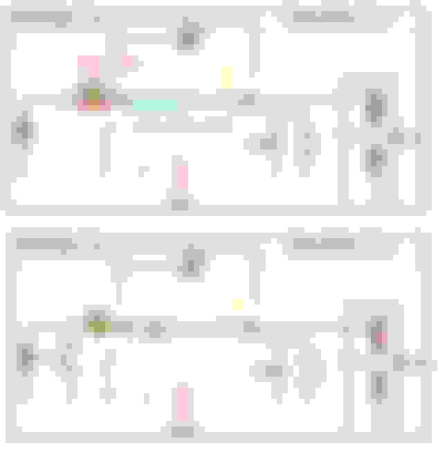
gOrsq, do you have available a "complete schematic like the one attached for the N82-1?
Also, found a board with very detailed connections schematic and wonder if anyone has a similar for the A-230-540-1045 board.
Will be helpful also to find a similar schematic for the W211 or W221..! Also attaching a great info on reading Benz schematics!
2000 R170 SLK 320 manual, 2018 E200 E Class Estate, 2016 GLA 250, 1996 R129 320, 2003 R230 500.
BCM Repairs R230
For what it is worth in a predominately US forum, I know of a technical repair shop in Leicester (UK) who repair these things all the time (unless of course they are burnt out).
The details are - send them an email first with some details.sales@autotronics.co.uk
Bismarck, thanks for the suggestion..! Unfortunately, as you can see in post #5, my PC board was burned through and I learned that these boards are triple layer which makes it impossible to repair when the condition is like shown..! So, I can drive the car but lack of radio and perhaps roof controls...but I know that at one point in time I will find how to connect the cables that feed power to these accessories to make them work. I already installed a DC to DC charger that maintains the starter battery charged, so hopefully I will run into a good schematic that helps to find the right connections!
Bismarck, thanks for the suggestion..! Unfortunately, as you can see in post #5, my PC board was burned through and I learned that these boards are triple layer which makes it impossible to repair when the condition is like shown..! So, I can drive the car but lack of radio and perhaps roof controls...but I know that at one point in time I will find how to connect the cables that feed power to these accessories to make them work. I already installed a DC to DC charger that maintains the starter battery charged, so hopefully I will run into a good schematic that helps to find the right connections!
How did the DC to DC install work? You ran wires from the alternator to your front battery?
Das, my Dc to Dc charger works as follows. 30a is disconnected from the BCM and connected to a terminal of the DC_DC, the other terminal of the DC-DC is connected to terminal 30 on the BCM (Partially Burned BCM). Notice F52f1 is separated from the BCM. No 57 relay! I am studying the BCM outputs to see what turns the COMMAND unit on! Other than that the car runs fine and charges the starter battery flawlessly!
gOrsq, do you have available a "complete schematic like the one attached for the N82-1?
Also, found a board with very detailed connections schematic and wonder if anyone has a similar for the A-230-540-1045 board.
Will be helpful also to find a similar schematic for the W211 or W221..! Also attaching a great info on reading Benz schematics!
Electrical schematic for BCM
I did want to prepare a component level schematic of the BCM to understand its function better, but these boards are to valuable.
Someone in the UK wanted �300 for a badly burned BCM!!!
Repairable ones will be worth several hundred more than that I guess!!
Reverse engineering wont solve the supply issue, due to the software the boards contain.
You will see the output to K75 which controls all the consumer circuits, which will be missing on your BCM due to lack of battery voltage readings.
My friend, you are right, since in their lifetime the R-230 BCM will burn at anytime, scarcity will hit the market and if a replacement is not found, the cars will start selling cheap...! I saw some chinese versions in the internet for $1200.! Perhaps they are cloning the unit!
Thaks for the diagram. I already have a copy and have been studying it and trying to determine which connection disable the consumers...It has to be the same system used on VSR's that compares the two batteries voltage and cuts power to the "consumers" gate till the two batteries voltage equalizes..! Do you think is the relay 75? I could measure the voltage on terminal 10 to confirm!
When I connect the rear battery I can hear the R75 clicking, meaning that it is activating..!
I have my eye on the component N73 which is label DI control module..! What DI stands for. Do you have the document PE54.21-U-2104KA which describes that module?
By discarding possibilities I only see that the connect-disconnect function of consumers is in terminals 7 or 6 or 14! If you have info on the modules connecting to those please share!
"the impossible just takes a little longer than usually known techniques, and with the aid of quality know how, we will debunk that mysterious BCM..!"
gOrsq, an interesting update...! After digging for documentation found an schematic for a SL65 Black Series with a very simplified N82/1 schematic since it does have regular hydraulic brakes and perhaps lacks of some of the other conveniences found on the SL-500. I would discard the connection to N73 since my EIS is working properly. That leaves a couple of connections to CAN B (7 and 6 pins) .See the direct 12V power to a relay module K40/5..! The bottom line is that the missing link is in the communications with CAN B. By any change would you have around an schematic for X30/17 (CAN B)???Document PE 00.19-P-23000KK..!
What type of signal is sent from pins 6 and 7....voltage or pulses???
trying to determine which connection disable the consumers...
From my earlier post "You will see the output to K75 which controls all the consumer circuits, which will be missing on your BCM due to lack of battery voltage readings."
K75 activates in a "fault" condition, turning of consumers.
I have my eye on the component N73 which is label DI control module..! What DI stands for.
This is the EIS module
Pin 7 and 6 are CANBUS so digital pulses of about 5V relative to each other. Look on internet for CANBUS voltages.
Mercedes SLR McLaren 722 S Is Extremely Rare Example Modified by McLaren
Slideshow: A one-of-one U.S.-spec Mercedes-Benz SLR McLaren Roadster became even rarer after a factory-backed transformation at McLaren's headquarters.