
SL55/63/65/R230 AMG: ABC Valve Block reseal on SL55
 10-01-2016, 03:39 PM
#1
Super Member
Thread Starter

ABC Valve Block reseal on SL55
So I helped a friend of mine with a 2004 SL55 reseal one of his ABC valve blocks. His car would lower the front end after sitting for a few hours. He had tried getting the fluid flushed and new filter but it didn't help. He asked me to take pictures along the way so I thought I would share.
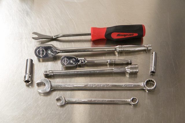
First step was to remove the valve block from the vehicle. I didn't take any pictures along the way but these are the tools I used minus a 17mm and breaker bar to remove the LF wheel
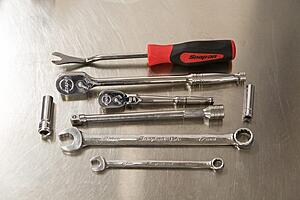
Be sure to clean the surrounding area really well before removal to avoid getting any dirt into the lines
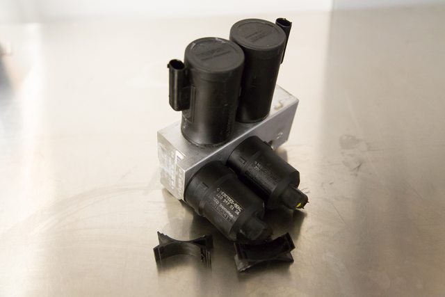
Here is the valve block out of the car, excuse the paint markings in the wrong spot as I quickly put the valves back in for a picture but put in opposite spots lol
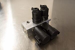
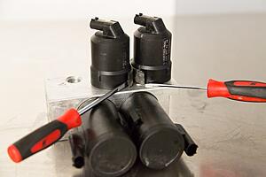
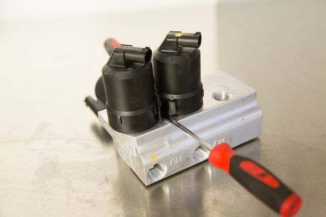
First step is to remove the plastic clips that hold the valves together. How I usually do this is to release one tab on one valve and turn it out of position so I don't have to fiddle with two sides at once, the turned side will be off of the lock tab that holds the clip in place. Here is an overhead view, notice it is only slightly turned. If you turn it too much it will be difficult to remove the clip.
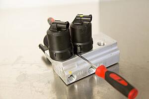
Once it is slightly turned I use a small screwdriver to push the clip out of the way and place another small screwdriver under the base of the clip to put a little pressure upwards
From there I leave one screwdriver underneath the clip and then loosen the clip on the other side of where that screwdriver is. once you push the clip off the lock it tends to move up and then I put the little screwdriver underneath and work it up from side to side
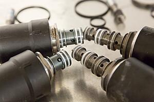
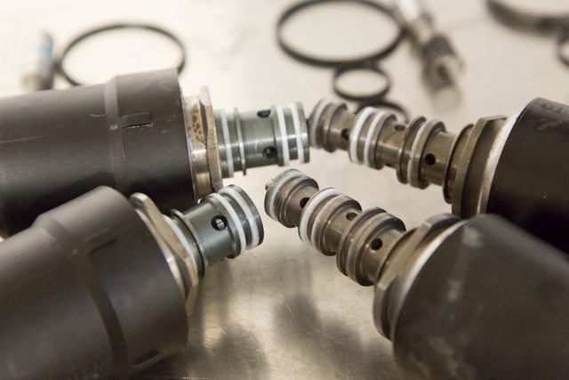
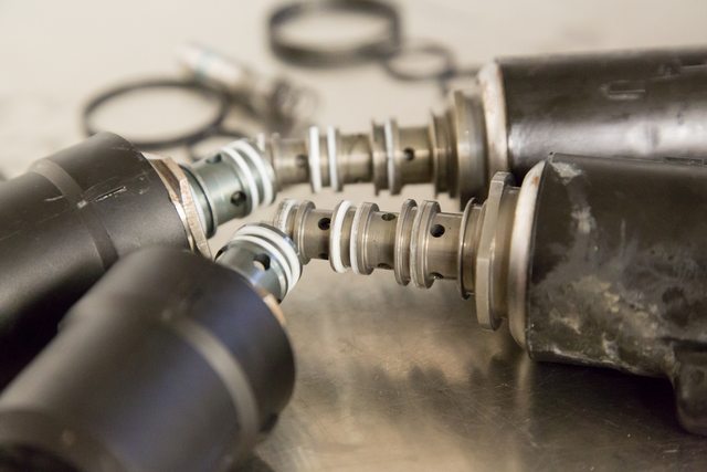
Do the same for the other pair of valves. For the locking valves I use my hand for the upward pressure as the clip is in the middle of the valves. From here you can rotate the valves 90 degrees on the control valves and about 45 degrees on the locking valves and then they can be pulled out of the valve block.
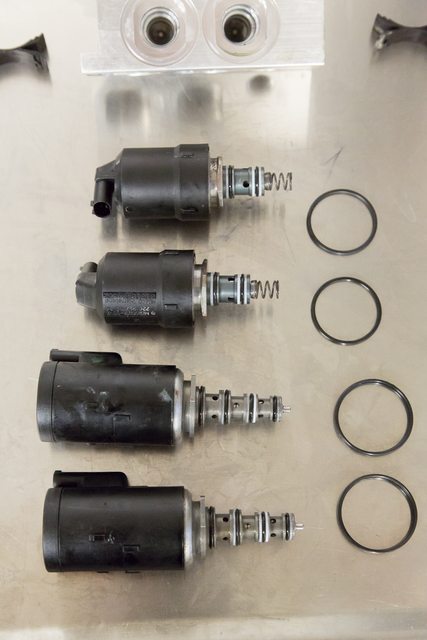
The big O-rings at the base of valves just seal outside moisture and such from getting in, They are not under hydraulic pressure so if they look a little dry it's OK. I have seen the tall ones replaced by using two O-rings, or using one O-ring and a small bead of silicone around the outside. Either way works.
I have never replaced or seen replaced the fat greenish blue O-ring on the shaft of the locking valve, I usually give everything a good cleaning and put the plungers back in with some new hydraulic fluid as lubricant. The springs on the plungers can be removed, I squeeze them to get a feel of strength, never had to replace them, I usually give them a little stretch to make just a hair longer incase they have become compressed over time.
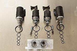
Inspect the white teflon spacers for any kind of damage, these rings don't offer any sealing, they mainly offer support to the sealing O-ring to help keep it in place. If they are damaged they can be replaced with rubber o-ring. The rings on these valves were in good shape so They just got a good cleaning with a tooth brush and a little solvent.
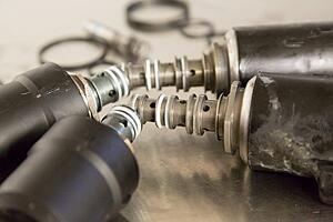
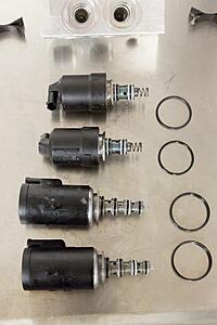
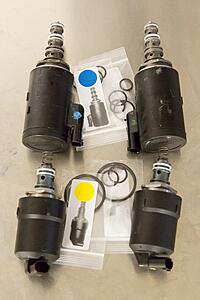
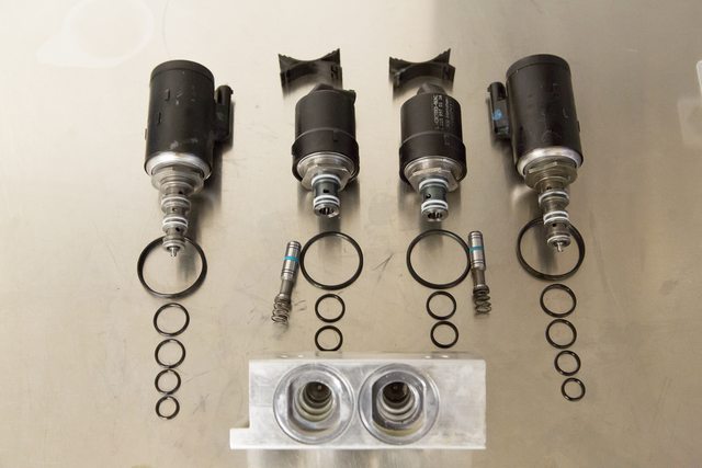
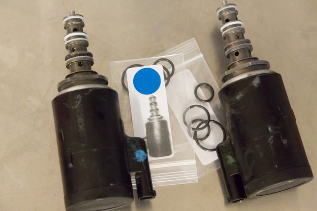
Here is a few pictures of the valves with their respective seals that will be getting installed after the valves receive a thorough cleaning. I didn't take pictures but I always like to apply power to the control valves in both directions and run solvent both ways through the passages just incase some gunk is caught up inside the valve. Also be sure and thoroughly clean the aluminum housing to get all old fluid and debris out of it.
After it is all cleaned up and new O-rings installed it's time to put the valves back in. I use plenty of new hydraulic oil to lubricate the valve with o-rings as well as the valve block itself. I always try and turn the valves in clockwise, sometimes the valve comes loose from housing turning the opposite way. Take your time putting them in to ensure you don't pinch an o-ring.
Once all valves are in place it's time to put the clips back on. Simply push the clips in between the valves and down into position.
Double check you have 14 old o-rings and no new o-rings on your workbench. After that put the valve block back in the car.
First step was to remove the valve block from the vehicle. I didn't take any pictures along the way but these are the tools I used minus a 17mm and breaker bar to remove the LF wheel
Be sure to clean the surrounding area really well before removal to avoid getting any dirt into the lines
Here is the valve block out of the car, excuse the paint markings in the wrong spot as I quickly put the valves back in for a picture but put in opposite spots lol

First step is to remove the plastic clips that hold the valves together. How I usually do this is to release one tab on one valve and turn it out of position so I don't have to fiddle with two sides at once, the turned side will be off of the lock tab that holds the clip in place. Here is an overhead view, notice it is only slightly turned. If you turn it too much it will be difficult to remove the clip.

Once it is slightly turned I use a small screwdriver to push the clip out of the way and place another small screwdriver under the base of the clip to put a little pressure upwards


From there I leave one screwdriver underneath the clip and then loosen the clip on the other side of where that screwdriver is. once you push the clip off the lock it tends to move up and then I put the little screwdriver underneath and work it up from side to side
Do the same for the other pair of valves. For the locking valves I use my hand for the upward pressure as the clip is in the middle of the valves. From here you can rotate the valves 90 degrees on the control valves and about 45 degrees on the locking valves and then they can be pulled out of the valve block.
The big O-rings at the base of valves just seal outside moisture and such from getting in, They are not under hydraulic pressure so if they look a little dry it's OK. I have seen the tall ones replaced by using two O-rings, or using one O-ring and a small bead of silicone around the outside. Either way works.
I have never replaced or seen replaced the fat greenish blue O-ring on the shaft of the locking valve, I usually give everything a good cleaning and put the plungers back in with some new hydraulic fluid as lubricant. The springs on the plungers can be removed, I squeeze them to get a feel of strength, never had to replace them, I usually give them a little stretch to make just a hair longer incase they have become compressed over time.
Inspect the white teflon spacers for any kind of damage, these rings don't offer any sealing, they mainly offer support to the sealing O-ring to help keep it in place. If they are damaged they can be replaced with rubber o-ring. The rings on these valves were in good shape so They just got a good cleaning with a tooth brush and a little solvent.
Here is a few pictures of the valves with their respective seals that will be getting installed after the valves receive a thorough cleaning. I didn't take pictures but I always like to apply power to the control valves in both directions and run solvent both ways through the passages just incase some gunk is caught up inside the valve. Also be sure and thoroughly clean the aluminum housing to get all old fluid and debris out of it.

After it is all cleaned up and new O-rings installed it's time to put the valves back in. I use plenty of new hydraulic oil to lubricate the valve with o-rings as well as the valve block itself. I always try and turn the valves in clockwise, sometimes the valve comes loose from housing turning the opposite way. Take your time putting them in to ensure you don't pinch an o-ring.

Once all valves are in place it's time to put the clips back on. Simply push the clips in between the valves and down into position.
Double check you have 14 old o-rings and no new o-rings on your workbench. After that put the valve block back in the car.


The following 3 users liked this post by knowbenz:
 10-04-2016, 04:17 PM
#4
Super Member
Thread Starter
The following users liked this post:
compaddict (10-04-2016)
10-05-2016, 10:21 AM
#5
MBWorld Fanatic!
Are these kits comprised of Viton or Buna-n o-rings?
I agree with you on the notion of stretching the springs slightly to increase preload on the locking valve seats. I had the front valve block out of my SL55 a week or so back (it was sinking as much as a couple of inches in as little as 1 hour on the left front corner) ... the rings looked good and there was scarcely and debris so I thoroughly cleaned the block and valves and then stretched the springs approx 0.45mm . Put it all back together and it is nearly perfect now. It still occasionally sinks a little on the LF (no more than 1/4", even sitting for a few days), but nearly good as new. I had a complete set of Viton 75 rings (except as it turns out, the -015 (?) I needed for the locking valve) so I will likely go back in and replace those at some later date.
here are a couple of pics for reference showing the spring(s) before and after "adjusting" them
Cheers,
Chris
Last edited by latemodel21; 10-05-2016 at 10:40 AM.
10-05-2016, 03:29 PM
#6
Super Member
Thread Starter
Nice write-up!
Are these kits comprised of Viton or Buna-n o-rings?
I agree with you on the notion of stretching the springs slightly to increase preload on the locking valve seats. I had the front valve block out of my SL55 a week or so back (it was sinking as much as a couple of inches in as little as 1 hour on the left front corner) ... the rings looked good and there was scarcely and debris so I thoroughly cleaned the block and valves and then stretched the springs approx 0.45mm . Put it all back together and it is nearly perfect now. It still occasionally sinks a little on the LF (no more than 1/4", even sitting for a few days), but nearly good as new. I had a complete set of Viton 75 rings (except as it turns out, the -015 (?) I needed for the locking valve) so I will likely go back in and replace those at some later date.
here are a couple of pics for reference showing the spring(s) before and after "adjusting" them
Cheers,
Chris
10-05-2016, 04:46 PM
#7
MBWorld Fanatic!
my $.02
Chris
Latemodel21 Products
Last edited by latemodel21; 10-05-2016 at 04:49 PM.
Trending Topics
10-05-2016, 10:08 PM
#8
Member


Anybody got a spare solenoid from an old valve block?
10-05-2016, 10:20 PM
#9
Super Member
Thread Starter
Dont try and change the plunger rings or even touch them.....there is a small oring under that "blue" ring which is like a flat teflon seal....you will **** it up if you touch it. Unfortunately I already touched one and did replace the oring but my S55 sinks quicker on one side now (a few hours, before it was days) so I know its the plunger. I actually used the Harbor freight green oring kit....not an "exact" fit but works ok. I got another spare set with the ebay oring kit and will rebuild that one and reinstall.......I will NOT touch the plunger this time around.
Anybody got a spare solenoid from an old valve block?
Anybody got a spare solenoid from an old valve block?
 10-09-2016, 02:39 PM
#10
Super Member
Thread Starter
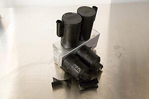
Thought I would throw this up here also. Did a second valve block using the square o-ring kit. The first one with square o-rings I did and the one from the first post on this thread are still holding up great. Pretty much everything is the same except for cutting off the teflon rings and replacing with a rubber square cut o-ring.
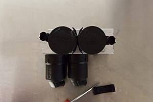
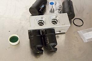
These didn't necessarily need to be replaced as the condition looked good. I started off by measuring all the different spots on the solenoid just to compare with the new rubber square rings. I've seen a kit before that that square rings were way to big and got cut upon installation.
Attachment 443103
Attachment 443104
I used a razor blade to cut the teflon rings off, they can also be removed like the o-rings with a seal tool or pocket screwdriver.
Attachment 443105
Attachment 443106
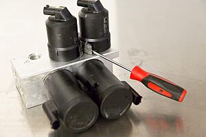
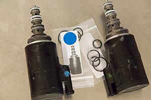
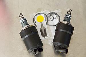
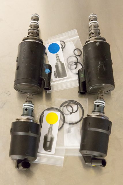
Here is everything being replaced with this kit, x2 for the other pair of valves not pictured
Attachment 443107
Attachment 443108
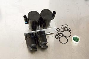
Install the new o-rings starting from the biggest side and go down in order. It is sometimes difficult to get a square o-ring around the round o-ring. Do one valve at a time so you don't forget the order they go, or just refer back to this thread.
Attachment 443109
Attachment 443110
As you can see the square rings don't protrude past the valves surface just how the teflon rings don't. Also, what is hard to capture on camera is that there is a slight amount of room left between the seals to allow for expansion of o-ring when the main o-ring gets compressed which is the same with the teflon rings installed.
The other setup I have seen has square rings that are damn near the same diameter as the round o-ring which makes installing the valve extremely difficult and ends up sheering off a few thousandths from the square rings and leaving loose rubber debris to make it's way into the hydraulic circuit.
One thing i want to stress is to make sure the square o-rings don't roll over when installing, it's easy to miss a small section that may not be fully seated and has to be rolled a little more. I found this out the hard way, the top seal on one control valve wasn't fully in place so when I went to install it it got cut. I should have rechecked when I realized this one was being a little difficult to get seated. Use lots of lube and twist back and forth the slight amount that it will to seat everything. I contacted the seller about the o-ring I broke and he asked which one it was and dropped one in the mail the same day. I should get it tomorrow and have this valve block wrapped up.
Attachment 443111
Attachment 443112
These didn't necessarily need to be replaced as the condition looked good. I started off by measuring all the different spots on the solenoid just to compare with the new rubber square rings. I've seen a kit before that that square rings were way to big and got cut upon installation.
Attachment 443103
Attachment 443104
I used a razor blade to cut the teflon rings off, they can also be removed like the o-rings with a seal tool or pocket screwdriver.
Attachment 443105
Attachment 443106
Here is everything being replaced with this kit, x2 for the other pair of valves not pictured
Attachment 443107
Attachment 443108
Install the new o-rings starting from the biggest side and go down in order. It is sometimes difficult to get a square o-ring around the round o-ring. Do one valve at a time so you don't forget the order they go, or just refer back to this thread.
Attachment 443109
Attachment 443110
As you can see the square rings don't protrude past the valves surface just how the teflon rings don't. Also, what is hard to capture on camera is that there is a slight amount of room left between the seals to allow for expansion of o-ring when the main o-ring gets compressed which is the same with the teflon rings installed.
The other setup I have seen has square rings that are damn near the same diameter as the round o-ring which makes installing the valve extremely difficult and ends up sheering off a few thousandths from the square rings and leaving loose rubber debris to make it's way into the hydraulic circuit.
One thing i want to stress is to make sure the square o-rings don't roll over when installing, it's easy to miss a small section that may not be fully seated and has to be rolled a little more. I found this out the hard way, the top seal on one control valve wasn't fully in place so when I went to install it it got cut. I should have rechecked when I realized this one was being a little difficult to get seated. Use lots of lube and twist back and forth the slight amount that it will to seat everything. I contacted the seller about the o-ring I broke and he asked which one it was and dropped one in the mail the same day. I should get it tomorrow and have this valve block wrapped up.
Attachment 443111
Attachment 443112
The following users liked this post:
compaddict (10-09-2016)
10-10-2016, 02:09 PM
#11
Senior Member

Join Date: Jul 2013
Location: Europe, but from Norway
Posts: 439
Received 46 Likes
on
41 Posts
89 SL500 Silver ,97 SL500 Carlsson 04 Mercedes SL55 AMG , 07 Mercedes SL55 AMG convertedBlack series
if y have a ABC system with little leak or sagging. use this product this guys have. it expand the rubber in O rings and soften up the hard rubber. they have 1 prosent expansion addetive that also help out on flow protect the pump, and the hardcore 3 prosent. we just added the one prosent hydraulic treatment type. and leak from shocks stopped on a 2004 model after few days. the 3 prosent type i stopped a leak in 2009 both shocks, 1 q or 1 liter was gone, and i just talked to owner now, and he has no issues on the car and abc . here is link . http://www.qmiitw.com/QMI_Engine.html now we added some of the 1 prosent type to a 2002 ,SL 350 that sagging when sit for some weeks, will se how that go.
10-10-2016, 03:50 PM
#12
Member
if y have a ABC system with little leak or sagging. use this product this guys have. it expand the rubber in O rings and soften up the hard rubber. they have 1 prosent expansion addetive that also help out on flow protect the pump, and the hardcore 3 prosent. we just added the one prosent hydraulic treatment type. and leak from shocks stopped on a 2004 model after few days. the 3 prosent type i stopped a leak in 2009 both shocks, 1 q or 1 liter was gone, and i just talked to owner now, and he has no issues on the car and abc . here is link . http://www.qmiitw.com/QMI_Engine.html now we added some of the 1 prosent type to a 2002 ,SL 350 that sagging when sit for some weeks, will se how that go.
10-10-2016, 04:14 PM
#13
Super Member
Thread Starter
if y have a ABC system with little leak or sagging. use this product this guys have. it expand the rubber in O rings and soften up the hard rubber. they have 1 prosent expansion addetive that also help out on flow protect the pump, and the hardcore 3 prosent. we just added the one prosent hydraulic treatment type. and leak from shocks stopped on a 2004 model after few days. the 3 prosent type i stopped a leak in 2009 both shocks, 1 q or 1 liter was gone, and i just talked to owner now, and he has no issues on the car and abc . here is link . http://www.qmiitw.com/QMI_Engine.html now we added some of the 1 prosent type to a 2002 ,SL 350 that sagging when sit for some weeks, will se how that go.
10-11-2016, 11:04 PM
#15
Member
I actually use Mobil 1 ATF in my ABC and steering system............no issues, not hydroscopic and a hell of a lot cheaper than pentosin.....


