


D.I.Y. Aux-In on 2007 W203 (without the wiring harness) (Large Image Warning!)

Thread Starter
Newbie
Joined: Sep 2007
Posts: 6
Likes: 0
2003 VW Passat Wagon, 1995 LR Range Rover
Hello All.
Well, I'm mostly a lurker here, as I don't have the privilege of owning my own Mercedes yet. However, my uncle and my Dad both drive Mercedes, and occasionally I'll work on their cars, so I figured I'd contribute to the community.
Anyways, my uncle asked me last week if there was a way to install an Aux-In on his 2007 C230. His car was one of those that did not have the factory wiring harness installed. So, I poked around and did some research, and here's how you do it. (This was written as a PDF document, and I've attached it below. I've also tried to convert it over to a forum posting as best as I can. If you want to see the original or you want to print it out, look at the PDF, as it was designed to be printed). Please leave comments! (And if the images are too big, let me know and I'll resize them)
1 Disclaimers
Note: This mostly describes how to build the cable that is missing in the 2007 MB W203 for the Audio 20 stock headunit. Much of this was based on some educated guesses and a few google searches. However, I have successfully done this in my uncle�s car, and have him to thank for the pictures. Also, please note that you do this at your own risk. I take no responsibility if you screw up your headunit/car/iPod/etc... It�s fairly easy, but read it through first to make sure you understand it.
2 Background
It appears for the 2007 Model Year, Mercedes-Benz thought it would save a few dollars and decided not to wire up the auxiliary in on the W203 C-Class�s stock radio. This mean that, while the head unit remained the same, the wire that went from the head unit to the passenger-side footwell did not exist, making it very difficult to just buy the cable harness and add it. After doing some research, I found a posting on a Russian website (here) that had the pinout of the head unit. With this in hand, I went and made a cable from the harness and a CDRom Audio cable, slightly modified. After doing a little testing, it worked!
3 Preliminaries
This will only be a partial howto, since the steps to take apart the center console are already well documented, and can be found here. This howto created for the Audio 20 OEM headunit in a 2007 Mercedes Bend C230 that was lacking the factory wiring harness, but had the Aux-In feature. To test to see if you have the Aux-In feature, press and hold your "CDC" button for a few seconds. It should switch to Aux-In mode. If not, then this guide won�t work for you. Sorry! Your mileage may vary... be careful, and don�t do anything stupid.
3.1 Parts Needed

Figure 1: CDRom Audio Cable
3.2 Tools Needed
4 Making the Cable
We first need to make the cable for the Aux-In. Since Mercedes was kind enough to continue to use the same headunit, we don�t need to replace the headunit or do anything drastic. All we need to do is create the cable that goes between the Cable Harness and the headunit.
4.1 Modify the CDRom Connector
We need to cut the connector lengthwise, so one part of the connector has one of the wires (white), and the other has two wires (black and red). Your cable may vary, if you have four wires, decide which one will not be used, and group the others likewise. Just take your wire cutters, and cut lengthwise (parallel to the wires) down the connector. It should look like this when it�s done (Figure 2).

Figure 2: Modified Connector End
The two wires that are attached to each other (in my case, red and black) will become your Right Channel and Ground, respectively. The other wire (white), will be your Left Channel.
4.2 Attach the MB Cable Harness and the CDRom Cable
Now we need to join the two together. I highly recommend you solder and heatshrink the cables. You could also use butt-splices, but the wire gauge is so fine that you�ll have to be careful. Whatever your method of joining the cables together, PLEASE make sure it is insulated from itself and the outside world. You don�t really want it to accidentally brush the 12V line and fry your iPod. Also, eyeball the length. The original Mercedes Cable was probably long enough to reach the center console, but I left on the excess cable from the CDRom Cable as well, which guarantees that it will reach. Depending on your CDRom Cable, you may have add some wire to make it long enough. For us, we didn�t have to add any. It isn�t a big problem if you have excess, as we will tuck the slack away.
Okay, enough disclaimers. Here�s the wiring diagram:
Figure 3: Wiring Diagram
Since the Mercedes Cable has more than one ground connection (Brown and Bare), you can just tie them together for our purposes. When you�re done, the cable should look something like Figure 4. I would suggest testing it with your multimeter (grab your 3.5mm cable) to make sure it matches up and is working before you start trying to route the wire. See Figure 5 for the pinout.

Figure 4: Finished Cable

Figure 5: 3.5mm Pinout
5 Installation
5.1 Disassemble the Center Column
Okay, time to get messy (well, sorta). Pull apart your center console, and remove your Radio. Make sure to disconnect the connector harness and the antenna connections on the radio, as we�ll want it out of the way for a while. Also, while you�re at it, remove the two screws holding on the passenger kickplate. See Figures 6, 7 and 8.

Figure 6: Center Console

Figure 7: Kickplate Screw Holes

Figure 8: Kickplate Partially Lowered
Now, when I did the installation, I pulled out the glove box. I don�t recommend you do that, as there is a mechanical damper that is very difficult to get realigned. It is possible to remove it relatively easily, but for us, reinstalling it took well over half an hour.
With the screws undone, pull the passenger kickplate down just a little, to where you can see the insulation. You don�t need to remove this, as all we are going to do is stuff the excess wire here.
5.2 Wire Feeding
Now for the difficult part! The wire needs to be fed backwards from the passenger footwell back to the radio. You need to guide it from the passenger footwell back to the center console. You�ll want to feed the end that is going to the radio back up through the center console. See Figures 9 and 10.

Figure 9: Wire Route Path in Passenger Footwell

Figure 10: Wire Route Path in Center Console
Once you get the wire in the center console area, make sure you feed it through the opening in the big connector. You�ll want to use the opening that is right above the speaker and power wires, not the one above the fiber optic cables. See Figure 11.

Figure 11: Wire Route Path through Connector Harness
Once you have routed the wires from the passenger footwell up through the center console and through the connector harness, you just need to plug it in to the headunit. The single wire should connect to Pin 12 on the group of pins above the power and speaker connectors. The connector with two wires should be connected to Pins 5 and 6, with Pin 5 being your ground connection. Be careful, as these pins are fragile and can be easily broken. They should more or less slide on with relative ease. If there is any significant resistance, stop what you�re doing, and try to figure out what might be blocking the connector. When I did it, there were some burrs on one of the connectors that didn�t let it slide in easily. I rotated the single wire connector and it all slid together easily. See Figures 12 and 13.

Figure 12: Connection to Headunit
Figure 13: Connection to Headunit
Once you�ve connected your cable up to the headunit, go ahead and reconnect the cable harness as well, so that the headunit will have power. If you feel confident, reattach the antenna connections as well. Slide the headunit back into place.
6 Testing
Now it�s time to test to see if you did everything correctly. This is optional, but I suggest that you test it using an old CD player or Tape player that has no sentimental value to you. In the event that you miswire something, You don�t want to fry your iPod! Power on the headunit, and turn the volume all the way down. Attach one end ot the 3.5mm male-to-male cable to the Mercedes Cable, and attach the other end to the headphone jack of your audio source. Set your audio source to approximately 75% volume. Press and hold the "CDC" button on the headunit until it switches to Aux-In mode, and then slowly raise the volume on the headunit until you hear sound. Congratulations! . It should work the first time if you�ve been following the guide carefully. If it doesn�t, see Troubleshooting below. After you�re satisfied that it works, turn off your headunit and unplug the 3.5mm cable from the Mercedes Cable.
7 Finishing Touches
If everything works, we�re almost done! We just need to finish routing the cable up to the glove box. I tucked mine behind the lip of the passenger�s kickplate, but route as you see fit. There�s a lot of space right on top of the kickplate for excess wire to go, so just stuff it all back there. Make sure you route the cable up to the right side of the glovebox, and press it into place where the Aux-In cutout is. (you may need to punch or cut it out first... it should already be pre-scored for you. Use the X-Acto knife to cut it out). Figure 14 shows the general overview of how I routed the cable, with Figures 15 and 16 showing some closeups.

Figure 14: Passenger Compar tment Wire Route Path

Figure 15: Closeup on right-side kickplate

Figure 16: Closeup on right-side of glove box
Put the screws back in place for the kickpanel, and reassemble the center console. You�re done! Now go enjoy your tunes.
8 Troubleshooting
Okay, so you tested it and it wasn�t right. Don�t worry, it�s probably just a minor issue. When I first tried this, one of my clip-leads was bad, and it just so happened to be the ground connection. Go figure, eh? Took me a few minutes to figure out that it was the clip-lead and not my wiring. So, here�s a couple of things to check first.
If none of these are working, grab your multimeter, and beep out the wires with your 3.5mm connector.
Figure 17: 3.5mm Pinout
If there are shorts or breaks in the wire, you need to pull it out. However, if all you did was wire it up differently than how I did it, it�s relatively easy to fix that. All you need to do is make sure the wire carrying Ground is going to the Ground pin on the headunit. Likewise, make sure Left and Right are connected to their respective pins. Give it another go, and see if it worked! If not, and you�re still stuck, you might want to go seek out some help from a more technically proficient person. Good luck!
9 Closing
I hope this guide was able to help you add Aux-In to your C-Class Mercedes. This would also work on any other car, as long as it has the SAME headunit. Good luck, and feel free to send me comments.
10 Appendix A
This appendix contains the complete known pinout of the Audio 20 Headunit. Again, most of this was culled from the Russian website. Note that pin names in quotes (" � ") means the literal translation, and I have not figured out exactly what its function is. Also, there is no pinout for Connector 4.

Figure 18: Pinout Diagram for Audio 20 Headunit
Well, I'm mostly a lurker here, as I don't have the privilege of owning my own Mercedes yet. However, my uncle and my Dad both drive Mercedes, and occasionally I'll work on their cars, so I figured I'd contribute to the community.
Anyways, my uncle asked me last week if there was a way to install an Aux-In on his 2007 C230. His car was one of those that did not have the factory wiring harness installed. So, I poked around and did some research, and here's how you do it. (This was written as a PDF document, and I've attached it below. I've also tried to convert it over to a forum posting as best as I can. If you want to see the original or you want to print it out, look at the PDF, as it was designed to be printed). Please leave comments! (And if the images are too big, let me know and I'll resize them)
---- ---- ---- ---- ---- ---- ---- ----
Aux-In on a 2007 Mercedes-Benz W203 (C230)
tbirdsaw
Aux-In on a 2007 Mercedes-Benz W203 (C230)
tbirdsaw
1 Disclaimers
Note: This mostly describes how to build the cable that is missing in the 2007 MB W203 for the Audio 20 stock headunit. Much of this was based on some educated guesses and a few google searches. However, I have successfully done this in my uncle�s car, and have him to thank for the pictures. Also, please note that you do this at your own risk. I take no responsibility if you screw up your headunit/car/iPod/etc... It�s fairly easy, but read it through first to make sure you understand it.
2 Background
It appears for the 2007 Model Year, Mercedes-Benz thought it would save a few dollars and decided not to wire up the auxiliary in on the W203 C-Class�s stock radio. This mean that, while the head unit remained the same, the wire that went from the head unit to the passenger-side footwell did not exist, making it very difficult to just buy the cable harness and add it. After doing some research, I found a posting on a Russian website (here) that had the pinout of the head unit. With this in hand, I went and made a cable from the harness and a CDRom Audio cable, slightly modified. After doing a little testing, it worked!
3 Preliminaries
This will only be a partial howto, since the steps to take apart the center console are already well documented, and can be found here. This howto created for the Audio 20 OEM headunit in a 2007 Mercedes Bend C230 that was lacking the factory wiring harness, but had the Aux-In feature. To test to see if you have the Aux-In feature, press and hold your "CDC" button for a few seconds. It should switch to Aux-In mode. If not, then this guide won�t work for you. Sorry! Your mileage may vary... be careful, and don�t do anything stupid.
3.1 Parts Needed
- Audio 20 Headunit (in your car)
- Old analog CDRom Audio Cable (see Figure 1)
- Mercedes-Benz Cable Harness A 203 540 61 07
- 3.5mm male to male connector (used to attach an audio source to the headunit)
- Old portable CD/Tape player or Radio, with headphone out (optional)
Figure 1: CDRom Audio Cable
3.2 Tools Needed
- Soldering Iron
- Heat-Shrink Tubing
- Wire strippers
- Wire cutters
- MultiMeter, preferably with a continuity tester
- X-Acto knife (optional, for cutting out the Aux-In panel)
4 Making the Cable
We first need to make the cable for the Aux-In. Since Mercedes was kind enough to continue to use the same headunit, we don�t need to replace the headunit or do anything drastic. All we need to do is create the cable that goes between the Cable Harness and the headunit.
4.1 Modify the CDRom Connector
We need to cut the connector lengthwise, so one part of the connector has one of the wires (white), and the other has two wires (black and red). Your cable may vary, if you have four wires, decide which one will not be used, and group the others likewise. Just take your wire cutters, and cut lengthwise (parallel to the wires) down the connector. It should look like this when it�s done (Figure 2).
Figure 2: Modified Connector End
The two wires that are attached to each other (in my case, red and black) will become your Right Channel and Ground, respectively. The other wire (white), will be your Left Channel.
4.2 Attach the MB Cable Harness and the CDRom Cable
Now we need to join the two together. I highly recommend you solder and heatshrink the cables. You could also use butt-splices, but the wire gauge is so fine that you�ll have to be careful. Whatever your method of joining the cables together, PLEASE make sure it is insulated from itself and the outside world. You don�t really want it to accidentally brush the 12V line and fry your iPod. Also, eyeball the length. The original Mercedes Cable was probably long enough to reach the center console, but I left on the excess cable from the CDRom Cable as well, which guarantees that it will reach. Depending on your CDRom Cable, you may have add some wire to make it long enough. For us, we didn�t have to add any. It isn�t a big problem if you have excess, as we will tuck the slack away.
Okay, enough disclaimers. Here�s the wiring diagram:
Code:
CDRom Cable	↔	Mercedes Cable
Red (Left)	↔	Yellow
White (Right)	↔	Black
Black (Ground)	↔	Brown
 		↔	Bare
Since the Mercedes Cable has more than one ground connection (Brown and Bare), you can just tie them together for our purposes. When you�re done, the cable should look something like Figure 4. I would suggest testing it with your multimeter (grab your 3.5mm cable) to make sure it matches up and is working before you start trying to route the wire. See Figure 5 for the pinout.
Figure 4: Finished Cable
Figure 5: 3.5mm Pinout
5 Installation
5.1 Disassemble the Center Column
Okay, time to get messy (well, sorta). Pull apart your center console, and remove your Radio. Make sure to disconnect the connector harness and the antenna connections on the radio, as we�ll want it out of the way for a while. Also, while you�re at it, remove the two screws holding on the passenger kickplate. See Figures 6, 7 and 8.
Figure 6: Center Console
Figure 7: Kickplate Screw Holes
Figure 8: Kickplate Partially Lowered
Now, when I did the installation, I pulled out the glove box. I don�t recommend you do that, as there is a mechanical damper that is very difficult to get realigned. It is possible to remove it relatively easily, but for us, reinstalling it took well over half an hour.
With the screws undone, pull the passenger kickplate down just a little, to where you can see the insulation. You don�t need to remove this, as all we are going to do is stuff the excess wire here.
5.2 Wire Feeding
Now for the difficult part! The wire needs to be fed backwards from the passenger footwell back to the radio. You need to guide it from the passenger footwell back to the center console. You�ll want to feed the end that is going to the radio back up through the center console. See Figures 9 and 10.
Figure 9: Wire Route Path in Passenger Footwell
Figure 10: Wire Route Path in Center Console
Once you get the wire in the center console area, make sure you feed it through the opening in the big connector. You�ll want to use the opening that is right above the speaker and power wires, not the one above the fiber optic cables. See Figure 11.
Figure 11: Wire Route Path through Connector Harness
Once you have routed the wires from the passenger footwell up through the center console and through the connector harness, you just need to plug it in to the headunit. The single wire should connect to Pin 12 on the group of pins above the power and speaker connectors. The connector with two wires should be connected to Pins 5 and 6, with Pin 5 being your ground connection. Be careful, as these pins are fragile and can be easily broken. They should more or less slide on with relative ease. If there is any significant resistance, stop what you�re doing, and try to figure out what might be blocking the connector. When I did it, there were some burrs on one of the connectors that didn�t let it slide in easily. I rotated the single wire connector and it all slid together easily. See Figures 12 and 13.
Figure 12: Connection to Headunit
Figure 13: Connection to Headunit
Once you�ve connected your cable up to the headunit, go ahead and reconnect the cable harness as well, so that the headunit will have power. If you feel confident, reattach the antenna connections as well. Slide the headunit back into place.
6 Testing
Now it�s time to test to see if you did everything correctly. This is optional, but I suggest that you test it using an old CD player or Tape player that has no sentimental value to you. In the event that you miswire something, You don�t want to fry your iPod! Power on the headunit, and turn the volume all the way down. Attach one end ot the 3.5mm male-to-male cable to the Mercedes Cable, and attach the other end to the headphone jack of your audio source. Set your audio source to approximately 75% volume. Press and hold the "CDC" button on the headunit until it switches to Aux-In mode, and then slowly raise the volume on the headunit until you hear sound. Congratulations! . It should work the first time if you�ve been following the guide carefully. If it doesn�t, see Troubleshooting below. After you�re satisfied that it works, turn off your headunit and unplug the 3.5mm cable from the Mercedes Cable.
7 Finishing Touches
If everything works, we�re almost done! We just need to finish routing the cable up to the glove box. I tucked mine behind the lip of the passenger�s kickplate, but route as you see fit. There�s a lot of space right on top of the kickplate for excess wire to go, so just stuff it all back there. Make sure you route the cable up to the right side of the glovebox, and press it into place where the Aux-In cutout is. (you may need to punch or cut it out first... it should already be pre-scored for you. Use the X-Acto knife to cut it out). Figure 14 shows the general overview of how I routed the cable, with Figures 15 and 16 showing some closeups.
Figure 14: Passenger Compar tment Wire Route Path
Figure 15: Closeup on right-side kickplate
Figure 16: Closeup on right-side of glove box
Put the screws back in place for the kickpanel, and reassemble the center console. You�re done! Now go enjoy your tunes.
8 Troubleshooting
Okay, so you tested it and it wasn�t right. Don�t worry, it�s probably just a minor issue. When I first tried this, one of my clip-leads was bad, and it just so happened to be the ground connection. Go figure, eh? Took me a few minutes to figure out that it was the clip-lead and not my wiring. So, here�s a couple of things to check first.
- If you hear audio only coming out of the left speakers, recheck the connection to Pin 12. If it appears to be fine, try flipping the connector to Pins 5 and 6. You may have inadvertently swapped your Ground and Left Channel wires.
- If you don�t hear any audio at all, recheck the connection to Pin 5. That�s your Ground connection, and it needs to be connected before you�ll hear any audio through your headunit.
If none of these are working, grab your multimeter, and beep out the wires with your 3.5mm connector.
Figure 17: 3.5mm Pinout
If there are shorts or breaks in the wire, you need to pull it out. However, if all you did was wire it up differently than how I did it, it�s relatively easy to fix that. All you need to do is make sure the wire carrying Ground is going to the Ground pin on the headunit. Likewise, make sure Left and Right are connected to their respective pins. Give it another go, and see if it worked! If not, and you�re still stuck, you might want to go seek out some help from a more technically proficient person. Good luck!
9 Closing
I hope this guide was able to help you add Aux-In to your C-Class Mercedes. This would also work on any other car, as long as it has the SAME headunit. Good luck, and feel free to send me comments.
10 Appendix A
This appendix contains the complete known pinout of the Audio 20 Headunit. Again, most of this was culled from the Russian website. Note that pin names in quotes (" � ") means the literal translation, and I have not figured out exactly what its function is. Also, there is no pinout for Connector 4.
Figure 18: Pinout Diagram for Audio 20 Headunit
Code:
    Connector 1
    1	Speaker rear right +	5	Speaker rear right -
    2	Speaker front right +	6	Speaker front right -
    3	Speaker front left +	7	Speaker front left -
    4	Speaker rear left +	8	Speaker rear left -
    Figure 19: Pinout for Connector 1

    Connector 2
    9	CAN Low (CAN A)		13	"Power Antenna"
    10	Mute			14	"Not Busy"
    11	CAN High (CAN B)	15	"terminal 30"
    12	"terminal 31"		16	"Wake Up"
    Figure 20: Pinout for Connector 2

    Connector 3
    5	Ground		11	"Mass Aux-Connector"
    6	Aux-In Left	12	Aux-In Right
    Figure 21: Pinout for Connector 3

Junior Member
Joined: Nov 2008
Posts: 47
Likes: 0
2019 c300
My stock headunit is the one with the tape player. I am guessing this wont work for that model?
Since there is no aux or other button to push to activate the ipod wiring.
If there is a workaround I would be very happy to know.
Since there is no aux or other button to push to activate the ipod wiring.
If there is a workaround I would be very happy to know.
Thread Starter
Newbie
Joined: Sep 2007
Posts: 6
Likes: 0
2003 VW Passat Wagon, 1995 LR Range Rover
Thanks acr2001 and **** for the comments. I knew some people had been looking for a solution to this... I'm just happy I was able to figure it out.
richardlo, I don't think this particular method will work on the headunit with the tape player. If you can figure out how to get into the Aux-In mode, then there is a good chance that it probably has some pins on the back to feed the signal in.
Good luck!
I knew some people had been looking for a solution to this... I'm just happy I was able to figure it out.richardlo, I don't think this particular method will work on the headunit with the tape player. If you can figure out how to get into the Aux-In mode, then there is a good chance that it probably has some pins on the back to feed the signal in.
Good luck!
Trending Topics
Senior Member
Joined: Jan 2009
Posts: 252
Likes: 0
From: Houston
2007 C230 Sport
What is the control/display of the Ipod with this mod - Does it show "AUX - In" on the headunit and the track info on the dash display? Can you only control it with the steering wheel controls? How is the sound?
AWESOME post! THANKS!
AWESOME post! THANKS!
MB World Stories
The Best of Mercedes & AMG

Manual Mercedes? 6 Times Sindelfingen Let Drivers Have All The Fun
Verdad Gallardo
Mercedes SLR McLaren 722 S Is Extremely Rare Example Modified by McLaren
Verdad Gallardo
8 Classic Boxy Mercedes Designs That Have Aged Like Fine Wine
Verdad Gallardo
Flawlessly Restored Mercedes 190E Evo II Heads to Auction
Verdad Gallardo
Electric Mercedes C-Class Unveiled: 11 Things You Need to Know
Verdad Gallardo
Mercedes EQS Gets A Major Update: Everything You Need to Know
Verdad Gallardo
5 Underrated Mercedes-Benz Models That Don't Get the Love They Deserve
Verdad Gallardo
Mercedes 300D Has Pushed Well Past 1 Million Miles and It Ain't Stopping
Verdad Gallardo
10 Most Reliable Mercedes-Benz Models You Can Buy Used
Verdad Gallardo
Thread Starter
Newbie
Joined: Sep 2007
Posts: 6
Likes: 0
2003 VW Passat Wagon, 1995 LR Range Rover
EDC320: Do you mean to actually open up the headunit and pull the pins out? I believe they are soldered to a circuit board inside the headunit... hence my use of the CDRom cable to plug in/extend it. Besides, if anyone ever comes up with a more elegant way of doing it or has some third-party device that uses the Aux-In pins, all that is necessary to revert it back to stock is to unplug the custom cable and remove it from the car.
07 Benz: I believe all this does is provide the Auxiliary In to the Audio20 headunit. It's a straight audio connection, so there is no controls for the iPod available. Conversely, that means that all you would be able to control would be the volume. As a result, while you cannot control the iPod, anything with a headphone jack would work. Even an old 8-Track player (and that was waaay before my time. ) would work, provided it had a headphone output. And yes, I believe it just shows "Aux-In" on the headunit (and possibly the dash display... I don't own this car so I don't know for a fact).
So, in short: No iPod control, no Track Info, just a straight audio in connection.
Thanks to everyone for the comments.
07 Benz: I believe all this does is provide the Auxiliary In to the Audio20 headunit. It's a straight audio connection, so there is no controls for the iPod available. Conversely, that means that all you would be able to control would be the volume. As a result, while you cannot control the iPod, anything with a headphone jack would work. Even an old 8-Track player (and that was waaay before my time.
) would work, provided it had a headphone output. And yes, I believe it just shows "Aux-In" on the headunit (and possibly the dash display... I don't own this car so I don't know for a fact).So, in short: No iPod control, no Track Info, just a straight audio in connection.
Thanks to everyone for the comments.


Member
Joined: Aug 2002
Posts: 203
Likes: 0
From: NY
2015 ML350 4Matic
Sorry for the confusion.
I mean that we could remove the wiring with the pin attachments from the white plug that came with the aux-in cable and then use those originally pinned wires to run through the factory harness that plugs into the back of the radio. I did this when adding my aux-in cable to my 2001 C320 Comand unit as there were spaces into which the pins could be run. Then we could simply crack off the white plastic plug on the existing aux-in cable and run the cable into the existing factory harness without the need for making use of the CD ROM cable. I am looking at the picture on figure 11 and trying to see if the harness (through which you are running the cable) can hold the pins (maybe not).
I mean that we could remove the wiring with the pin attachments from the white plug that came with the aux-in cable and then use those originally pinned wires to run through the factory harness that plugs into the back of the radio. I did this when adding my aux-in cable to my 2001 C320 Comand unit as there were spaces into which the pins could be run. Then we could simply crack off the white plastic plug on the existing aux-in cable and run the cable into the existing factory harness without the need for making use of the CD ROM cable. I am looking at the picture on figure 11 and trying to see if the harness (through which you are running the cable) can hold the pins (maybe not).
Senior Member
Joined: Jan 2009
Posts: 252
Likes: 0
From: Houston
2007 C230 Sport
OK, so this doesnt work like the OEM integration kit, and you control the song choice with the ipod only? I assume it doesnt charge the ipod either? Has anyone done this yet to their car?? How is the sound quality?
Thread Starter
Newbie
Joined: Sep 2007
Posts: 6
Likes: 0
2003 VW Passat Wagon, 1995 LR Range Rover
EDC320: Hmm... so if I understand you, you're wondering if you can take the pins out of the white connector and plug it into the headunit? I don't believe it was long enough, and I was too cheap to go purchase the actual pin holder for the back of the Audio20 headunit. If you have access to the proper parts, by all means, use them, as it would guarantee that it would not slip off due to vibration or anything else. On my uncle's car, he wanted a quick and dirty hookup, and the Mercedes parts counter was closed, so we used the CDRom cable to connect the pins up and lengthen the cable. I know that older model years of the Mercedes had the cable to go from the Audio20 headunit to the passenger footwell, which is what that Aux-In cable was designed for, and I would assume that Mercedes used the proper connector for that.
Hope this helps! If I still didn't understand, I'm sorry. Just keep describing it until I figure out what you're saying.
07 Benz: This is nothing like the iPod OEM integration kit... this was created to use the Auxiliary-In on the headunit. So no, it won't control the iPod, and it won't charge it, won't show the track info, etc... Think of it as turning your car into a very expensive set of mobile speakers. Sound quality should be a lot better than using a FM transmitter, but it wouldn't be as good as having a direct digital input into a headunit. On the flip side, this means that for everyone else who has a Zune, a Sansa, a Tape Recorder, an 8-Track, a MiniDisc, and so on and so forth, can use this Aux-In to play back audio in their car. As long as your device has a headphone out or something similar, you can use it with this project. This also means that any newer devices can be used with your car as well, even after CDRoms and iPods have gone the way of the Dodo, as long as they have a headphone out. As I said earlier, think of this project as turning your car into a very expensive set of speakers (although I've seen some crazy setups that cost WAY more than most cars  ).
).
To everyone, thank you for your comments.
Hope this helps! If I still didn't understand, I'm sorry. Just keep describing it until I figure out what you're saying.
07 Benz: This is nothing like the iPod OEM integration kit... this was created to use the Auxiliary-In on the headunit. So no, it won't control the iPod, and it won't charge it, won't show the track info, etc... Think of it as turning your car into a very expensive set of mobile speakers.
Sound quality should be a lot better than using a FM transmitter, but it wouldn't be as good as having a direct digital input into a headunit. On the flip side, this means that for everyone else who has a Zune, a Sansa, a Tape Recorder, an 8-Track, a MiniDisc, and so on and so forth, can use this Aux-In to play back audio in their car. As long as your device has a headphone out or something similar, you can use it with this project. This also means that any newer devices can be used with your car as well, even after CDRoms and iPods have gone the way of the Dodo, as long as they have a headphone out. As I said earlier, think of this project as turning your car into a very expensive set of speakers (although I've seen some crazy setups that cost WAY more than most cars ).To everyone, thank you for your comments.
Senior Member
Joined: Jan 2009
Posts: 252
Likes: 0
From: Houston
2007 C230 Sport
07 Benz: This is nothing like the iPod OEM integration kit... this was created to use the Auxiliary-In on the headunit. So no, it won't control the iPod, and it won't charge it, won't show the track info, etc... Think of it as turning your car into a very expensive set of mobile speakers.
Sound quality should be a lot better than using a FM transmitter, but it wouldn't be as good as having a direct digital input into a headunit. On the flip side, this means that for everyone else who has a Zune, a Sansa, a Tape Recorder, an 8-Track, a MiniDisc, and so on and so forth, can use this Aux-In to play back audio in their car. As long as your device has a headphone out or something similar, you can use it with this project. This also means that any newer devices can be used with your car as well, even after CDRoms and iPods have gone the way of the Dodo, as long as they have a headphone out. As I said earlier, think of this project as turning your car into a very expensive set of speakers (although I've seen some crazy setups that cost WAY more than most cars ).To everyone, thank you for your comments.

Member
Joined: Aug 2002
Posts: 203
Likes: 0
From: NY
2015 ML350 4Matic
Thank you for the follow-up.
Your detailed instructions are incredible.
After taking the white connector off the factory cable I see that the connections are too large for the back of the head unit, therefore I am following your approach using the cd rom cable.
This should be a sticky.
Your detailed instructions are incredible.
After taking the white connector off the factory cable I see that the connections are too large for the back of the head unit, therefore I am following your approach using the cd rom cable.
This should be a sticky.

Newbie
Joined: Feb 2009
Posts: 3
Likes: 0
car
so good Idea for wire harness
so good Idea for wire harness
Hello All.
Well, I'm mostly a lurker here, as I don't have the privilege of owning my own Mercedes yet. However, my uncle and my Dad both drive Mercedes, and occasionally I'll work on their cars, so I figured I'd contribute to the community.
Anyways, my uncle asked me last week if there was a way to install an Aux-In on his 2007 C230. His car was one of those that did not have the factory wiring harness installed. So, I poked around and did some research, and here's how you do it. (This was written as a PDF document, and I've attached it below. I've also tried to convert it over to a forum posting as best as I can. If you want to see the original or you want to print it out, look at the PDF, as it was designed to be printed). Please leave comments! (And if the images are too big, let me know and I'll resize them)
1 Disclaimers
Note: This mostly describes how to build the cable that is missing in the 2007 MB W203 for the Audio 20 stock headunit. Much of this was based on some educated guesses and a few google searches. However, I have successfully done this in my uncle�s car, and have him to thank for the pictures. Also, please note that you do this at your own risk. I take no responsibility if you screw up your headunit/car/iPod/etc... It�s fairly easy, but read it through first to make sure you understand it.
2 Background
It appears for the 2007 Model Year, Mercedes-Benz thought it would save a few dollars and decided not to wire up the auxiliary in on the W203 C-Class�s stock radio. This mean that, while the head unit remained the same, the wire that went from the head unit to the passenger-side footwell did not exist, making it very difficult to just buy the cable harness and add it. After doing some research, I found a posting on a Russian website (here) that had the pinout of the head unit. With this in hand, I went and made a cable from the harness and a CDRom Audio cable, slightly modified. After doing a little testing, it worked!
3 Preliminaries
This will only be a partial howto, since the steps to take apart the center console are already well documented, and can be found here. This howto created for the Audio 20 OEM headunit in a 2007 Mercedes Bend C230 that was lacking the factory wiring harness, but had the Aux-In feature. To test to see if you have the Aux-In feature, press and hold your "CDC" button for a few seconds. It should switch to Aux-In mode. If not, then this guide won�t work for you. Sorry! Your mileage may vary... be careful, and don�t do anything stupid.
3.1 Parts Needed
Figure 1: CDRom Audio Cable
3.2 Tools Needed
We first need to make the cable for the Aux-In. Since Mercedes was kind enough to continue to use the same headunit, we don�t need to replace the headunit or do anything drastic. All we need to do is create the cable that goes between the Cable Harness and the headunit.
4.1 Modify the CDRom Connector
We need to cut the connector lengthwise, so one part of the connector has one of the wires (white), and the other has two wires (black and red). Your cable may vary, if you have four wires, decide which one will not be used, and group the others likewise. Just take your wire cutters, and cut lengthwise (parallel to the wires) down the connector. It should look like this when it�s done (Figure 2).
Figure 2: Modified Connector End
The two wires that are attached to each other (in my case, red and black) will become your Right Channel and Ground, respectively. The other wire (white), will be your Left Channel.
4.2 Attach the MB Cable Harness and the CDRom Cable
Now we need to join the two together. I highly recommend you solder and heatshrink the cables. You could also use butt-splices, but the wire gauge is so fine that you�ll have to be careful. Whatever your method of joining the cables together, PLEASE make sure it is insulated from itself and the outside world. You don�t really want it to accidentally brush the 12V line and fry your iPod. Also, eyeball the length. The original Mercedes Cable was probably long enough to reach the center console, but I left on the excess cable from the CDRom Cable as well, which guarantees that it will reach. Depending on your CDRom Cable, you may have add some wire to make it long enough. For us, we didn�t have to add any. It isn�t a big problem if you have excess, as we will tuck the slack away.
Okay, enough disclaimers. Here�s the wiring diagram:
Well, I'm mostly a lurker here, as I don't have the privilege of owning my own Mercedes yet. However, my uncle and my Dad both drive Mercedes, and occasionally I'll work on their cars, so I figured I'd contribute to the community.
Anyways, my uncle asked me last week if there was a way to install an Aux-In on his 2007 C230. His car was one of those that did not have the factory wiring harness installed. So, I poked around and did some research, and here's how you do it. (This was written as a PDF document, and I've attached it below. I've also tried to convert it over to a forum posting as best as I can. If you want to see the original or you want to print it out, look at the PDF, as it was designed to be printed). Please leave comments! (And if the images are too big, let me know and I'll resize them)
---- ---- ---- ---- ---- ---- ---- ----
Aux-In on a 2007 Mercedes-Benz W203 (C230)
tbirdsaw
tbirdsaw
1 Disclaimers
Note: This mostly describes how to build the cable that is missing in the 2007 MB W203 for the Audio 20 stock headunit. Much of this was based on some educated guesses and a few google searches. However, I have successfully done this in my uncle�s car, and have him to thank for the pictures. Also, please note that you do this at your own risk. I take no responsibility if you screw up your headunit/car/iPod/etc... It�s fairly easy, but read it through first to make sure you understand it.
2 Background
It appears for the 2007 Model Year, Mercedes-Benz thought it would save a few dollars and decided not to wire up the auxiliary in on the W203 C-Class�s stock radio. This mean that, while the head unit remained the same, the wire that went from the head unit to the passenger-side footwell did not exist, making it very difficult to just buy the cable harness and add it. After doing some research, I found a posting on a Russian website (here) that had the pinout of the head unit. With this in hand, I went and made a cable from the harness and a CDRom Audio cable, slightly modified. After doing a little testing, it worked!
3 Preliminaries
This will only be a partial howto, since the steps to take apart the center console are already well documented, and can be found here. This howto created for the Audio 20 OEM headunit in a 2007 Mercedes Bend C230 that was lacking the factory wiring harness, but had the Aux-In feature. To test to see if you have the Aux-In feature, press and hold your "CDC" button for a few seconds. It should switch to Aux-In mode. If not, then this guide won�t work for you. Sorry! Your mileage may vary... be careful, and don�t do anything stupid.
3.1 Parts Needed
- Audio 20 Headunit (in your car)
- Old analog CDRom Audio Cable (see Figure 1)
- Mercedes-Benz Cable Harness A 203 540 61 07
- 3.5mm male to male connector (used to attach an audio source to the headunit)
- Old portable CD/Tape player or Radio, with headphone out (optional)
Figure 1: CDRom Audio Cable
3.2 Tools Needed
- Soldering Iron
- Heat-Shrink Tubing
- Wire strippers
- Wire cutters
- MultiMeter, preferably with a continuity tester
- X-Acto knife (optional, for cutting out the Aux-In panel)
We first need to make the cable for the Aux-In. Since Mercedes was kind enough to continue to use the same headunit, we don�t need to replace the headunit or do anything drastic. All we need to do is create the cable that goes between the Cable Harness and the headunit.
4.1 Modify the CDRom Connector
We need to cut the connector lengthwise, so one part of the connector has one of the wires (white), and the other has two wires (black and red). Your cable may vary, if you have four wires, decide which one will not be used, and group the others likewise. Just take your wire cutters, and cut lengthwise (parallel to the wires) down the connector. It should look like this when it�s done (Figure 2).
Figure 2: Modified Connector End
The two wires that are attached to each other (in my case, red and black) will become your Right Channel and Ground, respectively. The other wire (white), will be your Left Channel.
4.2 Attach the MB Cable Harness and the CDRom Cable
Now we need to join the two together. I highly recommend you solder and heatshrink the cables. You could also use butt-splices, but the wire gauge is so fine that you�ll have to be careful. Whatever your method of joining the cables together, PLEASE make sure it is insulated from itself and the outside world. You don�t really want it to accidentally brush the 12V line and fry your iPod. Also, eyeball the length. The original Mercedes Cable was probably long enough to reach the center console, but I left on the excess cable from the CDRom Cable as well, which guarantees that it will reach. Depending on your CDRom Cable, you may have add some wire to make it long enough. For us, we didn�t have to add any. It isn�t a big problem if you have excess, as we will tuck the slack away.
Okay, enough disclaimers. Here�s the wiring diagram:
Code:
CDRom Cable ↔ Mercedes Cable
Code:
Red (Left) ↔ YellowWhite (Right) ↔ Black Black (Ground) ↔ Brown ↔ Bare
Figure 3: Wiring Diagram
Since the Mercedes Cable has more than one ground connection (Brown and Bare), you can just tie them together for our purposes. When you�re done, the cable should look something like Figure 4. I would suggest testing it with your multimeter (grab your 3.5mm cable) to make sure it matches up and is working before you start trying to route the wire. See Figure 5 for the pinout.
Figure 4: Finished Cable
Figure 5: 3.5mm Pinout
5 Installation
5.1 Disassemble the Center Column
Okay, time to get messy (well, sorta). Pull apart your center console, and remove your Radio. Make sure to disconnect the connector harness and the antenna connections on the radio, as we�ll want it out of the way for a while. Also, while you�re at it, remove the two screws holding on the passenger kickplate. See Figures 6, 7 and 8.
Figure 6: Center Console
Figure 7: Kickplate Screw Holes
Figure 8: Kickplate Partially Lowered
Now, when I did the installation, I pulled out the glove box. I don�t recommend you do that, as there is a mechanical damper that is very difficult to get realigned. It is possible to remove it relatively easily, but for us, reinstalling it took well over half an hour.
With the screws undone, pull the passenger kickplate down just a little, to where you can see the insulation. You don�t need to remove this, as all we are going to do is stuff the excess wire here.
5.2 Wire Feeding
Now for the difficult part! The wire needs to be fed backwards from the passenger footwell back to the radio. You need to guide it from the passenger footwell back to the center console. You�ll want to feed the end that is going to the radio back up through the center console. See Figures 9 and 10.
Figure 9: Wire Route Path in Passenger Footwell
Figure 10: Wire Route Path in Center Console
Once you get the wire in the center console area, make sure you feed it through the opening in the big connector. You�ll want to use the opening that is right above the speaker and power wires, not the one above the fiber optic cables. See Figure 11.
Figure 11: Wire Route Path through Connector Harness
Once you have routed the wires from the passenger footwell up through the center console and through the connector harness, you just need to plug it in to the headunit. The single wire should connect to Pin 12 on the group of pins above the power and speaker connectors. The connector with two wires should be connected to Pins 5 and 6, with Pin 5 being your ground connection. Be careful, as these pins are fragile and can be easily broken. They should more or less slide on with relative ease. If there is any significant resistance, stop what you�re doing, and try to figure out what might be blocking the connector. When I did it, there were some burrs on one of the connectors that didn�t let it slide in easily. I rotated the single wire connector and it all slid together easily. See Figures 12 and 13.
Figure 12: Connection to Headunit
Figure 13: Connection to Headunit
Once you�ve connected your cable up to the headunit, go ahead and reconnect the cable harness as well, so that the headunit will have power. If you feel confident, reattach the antenna connections as well. Slide the headunit back into place.
6 Testing
Now it�s time to test to see if you did everything correctly. This is optional, but I suggest that you test it using an old CD player or Tape player that has no sentimental value to you. In the event that you miswire something, You don�t want to fry your iPod! Power on the headunit, and turn the volume all the way down. Attach one end ot the 3.5mm male-to-male cable to the Mercedes Cable, and attach the other end to the headphone jack of your audio source. Set your audio source to approximately 75% volume. Press and hold the "CDC" button on the headunit until it switches to Aux-In mode, and then slowly raise the volume on the headunit until you hear sound. Congratulations! . It should work the first time if you�ve been following the guide carefully. If it doesn�t, see Troubleshooting below. After you�re satisfied that it works, turn off your headunit and unplug the 3.5mm cable from the Mercedes Cable.
7 Finishing Touches
If everything works, we�re almost done! We just need to finish routing the cable up to the glove box. I tucked mine behind the lip of the passenger�s kickplate, but route as you see fit. There�s a lot of space right on top of the kickplate for excess wire to go, so just stuff it all back there. Make sure you route the cable up to the right side of the glovebox, and press it into place where the Aux-In cutout is. (you may need to punch or cut it out first... it should already be pre-scored for you. Use the X-Acto knife to cut it out). Figure 14 shows the general overview of how I routed the cable, with Figures 15 and 16 showing some closeups.
Figure 14: Passenger Compar tment Wire Route Path
Figure 15: Closeup on right-side kickplate
Figure 16: Closeup on right-side of glove box
Put the screws back in place for the kickpanel, and reassemble the center console. You�re done! Now go enjoy your tunes.
8 Troubleshooting
Okay, so you tested it and it wasn�t right. Don�t worry, it�s probably just a minor issue. When I first tried this, one of my clip-leads was bad, and it just so happened to be the ground connection. Go figure, eh? Took me a few minutes to figure out that it was the clip-lead and not my wiring. So, here�s a couple of things to check first.
Figure 17: 3.5mm Pinout
If there are shorts or breaks in the wire, you need to pull it out. However, if all you did was wire it up differently than how I did it, it�s relatively easy to fix that. All you need to do is make sure the wire carrying Ground is going to the Ground pin on the headunit. Likewise, make sure Left and Right are connected to their respective pins. Give it another go, and see if it worked! If not, and you�re still stuck, you might want to go seek out some help from a more technically proficient person. Good luck!
9 Closing
I hope this guide was able to help you add Aux-In to your C-Class Mercedes. This would also work on any other car, as long as it has the SAME headunit. Good luck, and feel free to send me comments.
10 Appendix A
This appendix contains the complete known pinout of the Audio 20 Headunit. Again, most of this was culled from the Russian website. Note that pin names in quotes (" � ") means the literal translation, and I have not figured out exactly what its function is. Also, there is no pinout for Connector 4.
Figure 18: Pinout Diagram for Audio 20 Headunit
Since the Mercedes Cable has more than one ground connection (Brown and Bare), you can just tie them together for our purposes. When you�re done, the cable should look something like Figure 4. I would suggest testing it with your multimeter (grab your 3.5mm cable) to make sure it matches up and is working before you start trying to route the wire. See Figure 5 for the pinout.
Figure 4: Finished Cable
Figure 5: 3.5mm Pinout
5 Installation
5.1 Disassemble the Center Column
Okay, time to get messy (well, sorta). Pull apart your center console, and remove your Radio. Make sure to disconnect the connector harness and the antenna connections on the radio, as we�ll want it out of the way for a while. Also, while you�re at it, remove the two screws holding on the passenger kickplate. See Figures 6, 7 and 8.
Figure 6: Center Console
Figure 7: Kickplate Screw Holes
Figure 8: Kickplate Partially Lowered
Now, when I did the installation, I pulled out the glove box. I don�t recommend you do that, as there is a mechanical damper that is very difficult to get realigned. It is possible to remove it relatively easily, but for us, reinstalling it took well over half an hour.
With the screws undone, pull the passenger kickplate down just a little, to where you can see the insulation. You don�t need to remove this, as all we are going to do is stuff the excess wire here.
5.2 Wire Feeding
Now for the difficult part! The wire needs to be fed backwards from the passenger footwell back to the radio. You need to guide it from the passenger footwell back to the center console. You�ll want to feed the end that is going to the radio back up through the center console. See Figures 9 and 10.
Figure 9: Wire Route Path in Passenger Footwell
Figure 10: Wire Route Path in Center Console
Once you get the wire in the center console area, make sure you feed it through the opening in the big connector. You�ll want to use the opening that is right above the speaker and power wires, not the one above the fiber optic cables. See Figure 11.
Figure 11: Wire Route Path through Connector Harness
Once you have routed the wires from the passenger footwell up through the center console and through the connector harness, you just need to plug it in to the headunit. The single wire should connect to Pin 12 on the group of pins above the power and speaker connectors. The connector with two wires should be connected to Pins 5 and 6, with Pin 5 being your ground connection. Be careful, as these pins are fragile and can be easily broken. They should more or less slide on with relative ease. If there is any significant resistance, stop what you�re doing, and try to figure out what might be blocking the connector. When I did it, there were some burrs on one of the connectors that didn�t let it slide in easily. I rotated the single wire connector and it all slid together easily. See Figures 12 and 13.
Figure 12: Connection to Headunit
Figure 13: Connection to Headunit
Once you�ve connected your cable up to the headunit, go ahead and reconnect the cable harness as well, so that the headunit will have power. If you feel confident, reattach the antenna connections as well. Slide the headunit back into place.
6 Testing
Now it�s time to test to see if you did everything correctly. This is optional, but I suggest that you test it using an old CD player or Tape player that has no sentimental value to you. In the event that you miswire something, You don�t want to fry your iPod! Power on the headunit, and turn the volume all the way down. Attach one end ot the 3.5mm male-to-male cable to the Mercedes Cable, and attach the other end to the headphone jack of your audio source. Set your audio source to approximately 75% volume. Press and hold the "CDC" button on the headunit until it switches to Aux-In mode, and then slowly raise the volume on the headunit until you hear sound. Congratulations! . It should work the first time if you�ve been following the guide carefully. If it doesn�t, see Troubleshooting below. After you�re satisfied that it works, turn off your headunit and unplug the 3.5mm cable from the Mercedes Cable.
7 Finishing Touches
If everything works, we�re almost done! We just need to finish routing the cable up to the glove box. I tucked mine behind the lip of the passenger�s kickplate, but route as you see fit. There�s a lot of space right on top of the kickplate for excess wire to go, so just stuff it all back there. Make sure you route the cable up to the right side of the glovebox, and press it into place where the Aux-In cutout is. (you may need to punch or cut it out first... it should already be pre-scored for you. Use the X-Acto knife to cut it out). Figure 14 shows the general overview of how I routed the cable, with Figures 15 and 16 showing some closeups.
Figure 14: Passenger Compar tment Wire Route Path
Figure 15: Closeup on right-side kickplate
Figure 16: Closeup on right-side of glove box
Put the screws back in place for the kickpanel, and reassemble the center console. You�re done! Now go enjoy your tunes.
8 Troubleshooting
Okay, so you tested it and it wasn�t right. Don�t worry, it�s probably just a minor issue. When I first tried this, one of my clip-leads was bad, and it just so happened to be the ground connection. Go figure, eh? Took me a few minutes to figure out that it was the clip-lead and not my wiring. So, here�s a couple of things to check first.
- If you hear audio only coming out of the left speakers, recheck the connection to Pin 12. If it appears to be fine, try flipping the connector to Pins 5 and 6. You may have inadvertently swapped your Ground and Left Channel wires.
- If you don�t hear any audio at all, recheck the connection to Pin 5. That�s your Ground connection, and it needs to be connected before you�ll hear any audio through your headunit.
Figure 17: 3.5mm Pinout
If there are shorts or breaks in the wire, you need to pull it out. However, if all you did was wire it up differently than how I did it, it�s relatively easy to fix that. All you need to do is make sure the wire carrying Ground is going to the Ground pin on the headunit. Likewise, make sure Left and Right are connected to their respective pins. Give it another go, and see if it worked! If not, and you�re still stuck, you might want to go seek out some help from a more technically proficient person. Good luck!
9 Closing
I hope this guide was able to help you add Aux-In to your C-Class Mercedes. This would also work on any other car, as long as it has the SAME headunit. Good luck, and feel free to send me comments.
10 Appendix A
This appendix contains the complete known pinout of the Audio 20 Headunit. Again, most of this was culled from the Russian website. Note that pin names in quotes (" � ") means the literal translation, and I have not figured out exactly what its function is. Also, there is no pinout for Connector 4.
Figure 18: Pinout Diagram for Audio 20 Headunit
Code:
Connector 1
Code:
1 Speaker rear right + 5 Speaker rear right -2 Speaker front right + 6 Speaker front right - 3 Speaker front left + 7 Speaker front left - 4 Speaker rear left + 8 Speaker rear left - Figure 19: Pinout for Connector 1Connector 2 9 CAN Low (CAN A) 13 "Power Antenna" 10 Mute 14 "Not Busy" 11 CAN High (CAN B) 15 "terminal 30" 12 "terminal 31" 16 "Wake Up" Figure 20: Pinout for Connector 2Connector 3 5 Ground 11 "Mass Aux-Connector" 6 Aux-In Left 12 Aux-In Right Figure 21: Pinout for Connector 3

Member
Joined: Jul 2007
Posts: 194
Likes: 0
2007 C230SS
Just a comment - I bet we really don't need to use the $30-40 MB aux cable ( A203 504 61 07). If all we need is a female aux in, maybe a radio shack aux in receptacle can be substituted. Thoughts ?
I started assembling the plug from the CD rom cable. very easy to do. I think removing the HU will the most difficult for this mod.
I started assembling the plug from the CD rom cable. very easy to do. I think removing the HU will the most difficult for this mod.

Newbie
Joined: Apr 2009
Posts: 6
Likes: 0
2007 C230
more on modified CD-ROM cable
Below my experience following the great post by Birdsaw.
First some comments on the removal of the head unit as explained in
https://mbworld.org/forums/c-class-w...oval-pics.html
While removing the ashtray. There is a picture that says "Use the flat head to pull the clip (both sides) forward then remove the complete ashtray" it took me more force than expected to push the clip. Similar experience with the step where you need to remove the climate unit. (See picture where it says using both hands, pull out the climate unit) you need to pull out hard, I almost chickened here it really took some force to remove the climate unit.
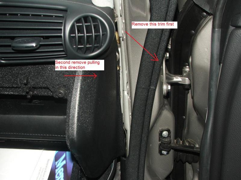
This was my first time I played around with my C230. Thus I had to figure out some basic stuff. For newbies like me check picture "remove_lateral_panel.jpg".

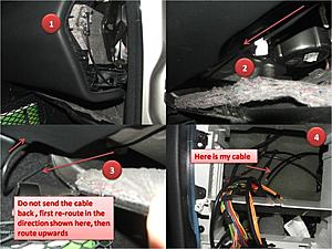
Now, with regards to the routing of the cable. Figure 8 in the instructions Birdsaw mentioned he removed the glove box. But himself recomend not to remove it. I did not remove mine, it took me some time to figure out how to route the cable, but I managed to do it, see attached picture "routing_the_cable.jpg"
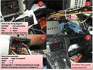
The CD-ROM cable I got was a little different from the one in the original post by Birdsaw, basically, the red and white where switched, I had a minor change in the wiring. Here is my wiring
CD-ROM Mercedes Cable
White (Left) -> Yellow
Red (Right) -> Black
Black(Ground) -> Brown and bare
Also as you will see in the picture I built the cable in the car (see "building_cable_and_connection_2_head_unit.jpg "), maybe not such a good idea, if you decided to do the same, be cautious with a possible dripping while soldering
Finally an issue I found we need to double check.
As right now it is working Ok, but I think the original post, and I may have an issue with the ground cable. Need some help here, please Birdsaw analize the picture I posted and your original picture (see figure 12 and 13 in your post) if you analyze the figures close enough you will find that the CD-ROM black cable is connected to pin 11, according with your own post, this may be wrong, pin number 5 is ground not pin 11, any advice?
thank you
earroyo
First some comments on the removal of the head unit as explained in
https://mbworld.org/forums/c-class-w...oval-pics.html
While removing the ashtray. There is a picture that says "Use the flat head to pull the clip (both sides) forward then remove the complete ashtray" it took me more force than expected to push the clip. Similar experience with the step where you need to remove the climate unit. (See picture where it says using both hands, pull out the climate unit) you need to pull out hard, I almost chickened here it really took some force to remove the climate unit.
This was my first time I played around with my C230. Thus I had to figure out some basic stuff. For newbies like me check picture "remove_lateral_panel.jpg".
Now, with regards to the routing of the cable. Figure 8 in the instructions Birdsaw mentioned he removed the glove box. But himself recomend not to remove it. I did not remove mine, it took me some time to figure out how to route the cable, but I managed to do it, see attached picture "routing_the_cable.jpg"

The CD-ROM cable I got was a little different from the one in the original post by Birdsaw, basically, the red and white where switched, I had a minor change in the wiring. Here is my wiring
CD-ROM Mercedes Cable
White (Left) -> Yellow
Red (Right) -> Black
Black(Ground) -> Brown and bare
Also as you will see in the picture I built the cable in the car (see "building_cable_and_connection_2_head_unit.jpg "), maybe not such a good idea, if you decided to do the same, be cautious with a possible dripping while soldering

Finally an issue I found we need to double check.
As right now it is working Ok, but I think the original post, and I may have an issue with the ground cable. Need some help here, please Birdsaw analize the picture I posted and your original picture (see figure 12 and 13 in your post) if you analyze the figures close enough you will find that the CD-ROM black cable is connected to pin 11, according with your own post, this may be wrong, pin number 5 is ground not pin 11, any advice?
thank you
earroyo
Thread Starter
Newbie
Joined: Sep 2007
Posts: 6
Likes: 0
2003 VW Passat Wagon, 1995 LR Range Rover
earroyo,
First off, sorry for not replying sooner. I've been working through my finals. Just finished the last of them today for the semester, so now I can answer your questions.
First, thanks for your clarifications on the guide. From what I can remember, removing the climate control and the ashtray was a bit difficult, but I was using another guide (don't remember exactly which one), and ended up muscling up a little to remove it. It was a little touch and go there, because I was working on my uncle's car, and didn't want to break anything, but I believe the other guide mentioned this, so I went ahead and popped it out.
Thank you also for the routing guide for people who don't remove the glove box. It truly was a pain getting it back in (maybe we were doing something wrong), but I wasn't about to re-route the wire after we pulled out the glove box.
Building the wire in a car is no fun... I've had to repair a CD-Changer connector in another car (not optical... 16-pin connector), and working with a hot soldering iron is no fun. That's why I make the cable before ripping the car apart.
Now that you mention it, I did wire it up wrong. Good eyes! My uncle hasn't complained about it once... so I don't know if it matters. You are correct though in saying that it is wired up wrong... according to the diagram, Pin 11 is something else, and I *should* be using Pin 5.
If anyone has wired it up to Pin 5 rather than Pin 11, could they report back and let me know if it worked properly? Or has everyone been wiring it to Pin 5 rather than Pin 11?
Again, thanks for the comments!
First off, sorry for not replying sooner. I've been working through my finals. Just finished the last of them today for the semester, so now I can answer your questions.
First, thanks for your clarifications on the guide. From what I can remember, removing the climate control and the ashtray was a bit difficult, but I was using another guide (don't remember exactly which one), and ended up muscling up a little to remove it. It was a little touch and go there, because I was working on my uncle's car, and didn't want to break anything, but I believe the other guide mentioned this, so I went ahead and popped it out.
Thank you also for the routing guide for people who don't remove the glove box. It truly was a pain getting it back in (maybe we were doing something wrong), but I wasn't about to re-route the wire after we pulled out the glove box.
Building the wire in a car is no fun... I've had to repair a CD-Changer connector in another car (not optical... 16-pin connector), and working with a hot soldering iron is no fun. That's why I make the cable before ripping the car apart.
Now that you mention it, I did wire it up wrong.
Good eyes! My uncle hasn't complained about it once... so I don't know if it matters. You are correct though in saying that it is wired up wrong... according to the diagram, Pin 11 is something else, and I *should* be using Pin 5. If anyone has wired it up to Pin 5 rather than Pin 11, could they report back and let me know if it worked properly? Or has everyone been wiring it to Pin 5 rather than Pin 11?
Again, thanks for the comments!
Newbie
Joined: Apr 2009
Posts: 6
Likes: 0
2007 C230
Thank you for taking the time to respond. I sure remember those days working on my finals... lots of work...
I agree with you, building the cable in the car was not fun (Possible dripping).
Regarding sound and pin connection, if I raise the volume and do not have my MP3 player connected, I notice on my car, I am having some background noise. As soon as I get some time, I am planning to re-open the front unit and connect the ground to pin 5 instead of pin 11. I will keep you posted on the results.
Meanwhile, can somebody check if they are having the same issue when not having your MP3 player connected?
Thank you,
Elkin Arroyo-Negrete
Last edited by earroyo; May 27, 2009 at 12:07 AM.


Senior Member
Joined: Mar 2008
Posts: 358
Likes: 0
From: San Pedro CA and Costa Mesa CA
2005 W203 SS
if you cant control your ipod from the center concel or steering wheel i dont think it worth taking out the dash...
i have the same setup and i connected the cable to between the passanger seat and the door. took me 10 min.
https://mbworld.org/forums/c-class-w...layer-etc.html
i have the same setup and i connected the cable to between the passanger seat and the door. took me 10 min.
https://mbworld.org/forums/c-class-w...layer-etc.html


