When you click on links to various merchants on this site and make a purchase, this can result in this site earning a commission. Affiliate programs and affiliations include, but are not limited to, the eBay Partner Network.
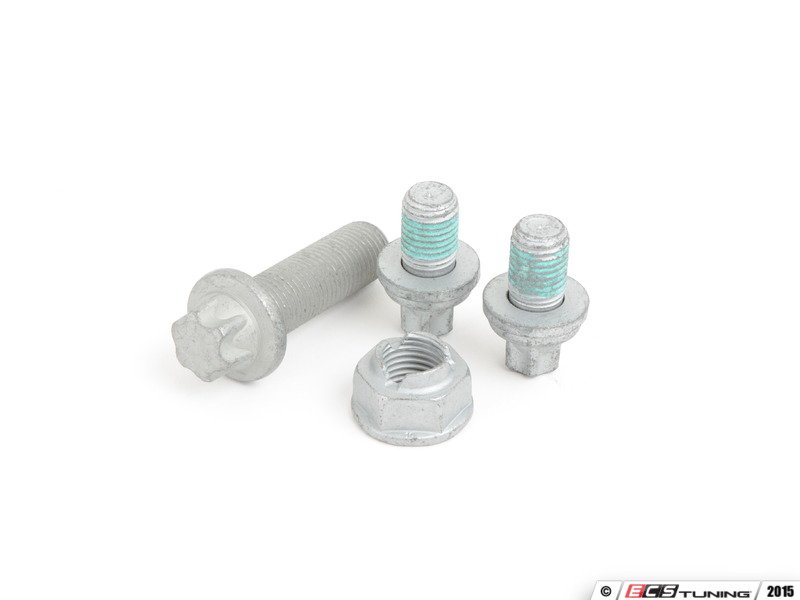
Wasted an hour trying to hunt down the equivalent kit from ECS which is way overpriced. Looking for the three bolts and one nut that mount each front strut to the knuckle for 2009 w/P30. I was under the car taking notes for Upper Control Arm swap and noticed those bolts, especially the larger upper, are nasty corroded. Can anyone dial me in? Every time I look at another parts diagram from the usual sites, they aren't showing the bolts and nut, except on other models...which then say "not compatible". Would have liked FCP to offer but couldn't find there either...
ECS: https://www.ecstuning.com/b-genuine-.../0009902403kt/
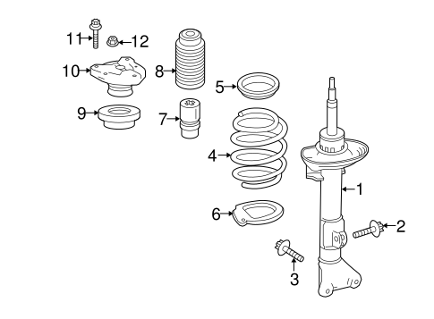
For the 2009 C63:
But for a '14 C63 Coupe the diagram shows:
So I'm after 2, and 3. But #2 also needs a corresponding nut.
Cheers and thanks. I guess after all this I shoulda just got the ECS kit...
Thanks all. This is what I need. I intend to replace that hardware when I install the new Syncro Upper Control Arms that Kyle at FCP was kind enough to set me up with. Will report back once they're in. I'm basically a "YouTube" mechanic and from what I've seen, it's fairly straightfoward. Unbolt the UCA, unbolt the strut from the knuckle for clearance of the UCA ball joint, remove, replace...
2012 C63;1971 280SE 3.5(Sold);2023 EQS 450 SUV 4 Matic (Wife's)
No need to unbolt the strut, up to you on that. Break the ball joint free from the strut and remove the bolt from the sub-frame.
The job will go much better with a ball joint removal tool. Here is a link, just for an example. I have this one and it works well.
For the Upper? "Thrust Arm"? I thought the ball joint sits under the strut, so you can't get it up out of the way unless the strut is removed? Like these guys?
2012 C63;1971 280SE 3.5(Sold);2023 EQS 450 SUV 4 Matic (Wife's)
I don't think you need to unbolt the strut to replace a control arm. If you can do it without unbolting the strut (I am sure you can) and you still want to replace the strut fasteners for any reason, then do them one at a time so that the spindle never floats free from the strut. The spindle with rotor and caliper attached is quite heavy and awkward to deal with and it can be difficult to get it lined up to reinstall the bottom fasteners even with the top bolt in for support. You will be far better off and happier if you do not unbolt the spindle from the strut.
2012 P31 C63 Coupe Trackrat, 2019 GLE63S Coupe Beast
The thrust arm ball joint removes upwards from the spindle. It�s wedged in there and removal is blocked by the strut itself. WIS shows to remove the strut just like that video. I looked at it for a good half hour and couldn�t see a smarter way to do it.
2012 C63;1971 280SE 3.5(Sold);2023 EQS 450 SUV 4 Matic (Wife's)
After watching the video you posted I went out and jacked the car up and had a closer look. I am sorry but I may have given you a little false hope. The clearance from the UCA to the bottom of the strut is probably too close to remove the UCA and the strut will have to be unbolted ( I am looking at KWV3 and not stock struts but the gap is likely the same). My apologies for jumping the gun and not looking before posting.
You will have to support the spindle and brake hardware somehow (maybe with the floor jack or a jack stand and some bailing wire to stabilize it to the car somehow as I can't remember exactly how I did it) and be careful not to put pressure on the brake line or abs sensor wires. Remove all control arm nuts and break the ball joint before you remove the strut fasteners to help reduce the time it will take to remove the control arm. The UCA chassis bolt can be tight to get out so have a plan for that as well. Having a buddy to help out is probably a good idea and you can celebrate with a couple of cold ones afterwards.
If you look carefully and think you can remove the ball joint nut and break the ball joint and remove the chassis end nut and bolt and free the UCA from the chassis you might just be able to wiggle it around enough to muscle it out. I would give that a try but be prepared to go the long route if that doesn't work. I am sorry but I can't remember if this will work but I am sure I gave it a try. I am almost sorry for mentioning this as I think I did try and was not successful. Look at the ball joint stem on the new control arm to make sure it is not longer than the stock one as you will have to wiggle it back in as well and it will be a lot stiffer and harder to manipulate as well.
Hope I didn't mess you up too much with all this. Best of luck replacing your control arm.
No worries, I'm just torn between DIY vs. $300 shop fee. I've got a second pair of hands, all the tools, the video seems straightforward, and I'm handy with the ball joint loaner tool I've got. IDK..."What could go wrong??"
I mean, if Jim hasn't installed his DIY, I sure as sh*t don't want to...
2012 P31 C63 Coupe Trackrat, 2019 GLE63S Coupe Beast
Originally Posted by Mort
After watching the video you posted I went out and jacked the car up and had a closer look. I am sorry but I may have given you a little false hope. The clearance from the UCA to the bottom of the strut is probably too close to remove the UCA and the strut will have to be unbolted ( I am looking at KWV3 and not stock struts but the gap is likely the same). My apologies for jumping the gun and not looking before posting.
You will have to support the spindle and brake hardware somehow (maybe with the floor jack or a jack stand and some bailing wire to stabilize it to the car somehow as I can't remember exactly how I did it) and be careful not to put pressure on the brake line or abs sensor wires. Remove all control arm nuts and break the ball joint before you remove the strut fasteners to help reduce the time it will take to remove the control arm. The UCA chassis bolt can be tight to get out so have a plan for that as well. Having a buddy to help out is probably a good idea and you can celebrate with a couple of cold ones afterwards.
If you look carefully and think you can remove the ball joint nut and break the ball joint and remove the chassis end nut and bolt and free the UCA from the chassis you might just be able to wiggle it around enough to muscle it out. I would give that a try but be prepared to go the long route if that doesn't work. I am sorry but I can't remember if this will work but I am sure I gave it a try. I am almost sorry for mentioning this as I think I did try and was not successful. Look at the ball joint stem on the new control arm to make sure it is not longer than the stock one as you will have to wiggle it back in as well and it will be a lot stiffer and harder to manipulate as well.
Hope I didn't mess you up too much with all this. Best of luck replacing your control arm.
Yeah, I thought the same thing too. That there was no way I had to disassemble everything on that side. I sat and looked, and looked, and measured. I just didn’t see it. I have just over a half inch from the top of the thrust arm ball joint to the lower strut mount. There’s probably enough room to pop the joint, but definitely not any more than that.
Originally Posted by Crya
No worries, I'm just torn between DIY vs. $300 shop fee. I've got a second pair of hands, all the tools, the video seems straightforward, and I'm handy with the ball joint loaner tool I've got. IDK..."What could go wrong??"
I mean, if Jim hasn't installed his DIY, I sure as sh*t don't want to...
Ha. I’m getting to it slowly. Been busy with work. Still wrestling with the racing seats. Then I have to finish my headlights. Then I need to unpack and setup the QuickJack. THEN I’m doing the SDW arms. I’ll get it done by the end of the month.
And if you have the tools already and the time, save yourself some money. It’s as straightforward as it gets. Post up the DIY when you’re done.
Yeah, I thought the same thing too. That there was no way I had to disassemble everything on that side. I sat and looked, and looked, and measured. I just didn�t see it. I have just over a half inch from the top of the thrust arm ball joint to the lower strut mount. There�s probably enough room to pop the joint, but definitely not any more than that.
Ha. I�m getting to it slowly. Been busy with work. Still wrestling with the racing seats. Then I have to finish my headlights. Then I need to unpack and setup the QuickJack. THEN I�m doing the SDW arms. I�ll get it done by the end of the month.
And if you have the tools already and the time, save yourself some money. It�s as straightforward as it gets. Post up the DIY when you�re done.
Thanks bro. I'll reassess once I get the pieces in. In the meantime, let's see those seats installed!
Alright I had enough free time today to just get the left side on. Basically just follow the video and torque specs here. Two main notes:
One thing that hung me up tool-wise was needing a 21mm combo wrench for counter holding the top strut nut as well as needing an open wrench again to tighten the knuckle side of the new arm because you�ll need to insert a 10mm hex into the bottom of the threaded stud to hold the ball in place as you tighten the 21mm nut. Removing the OE arm didn�t necessitate counter holding the stud, which used a torx fitting. I was able to get the nut all the off without any spinning of the ball.
The other was needing a ball joint separator. I had literally just borrowed one from Autozone last week to replacing some ball joints on my camper so back I went to check it out again. There�s just barely enough room to pound it onto the joint between the tie rod etc. I found that inserting the separator from inside facing towards the wheel allowed enough room to give it a few taps with a hammer. Safety glasses people. I cranked down on the tool and let it sit after I felt like there was enough pressure. I was turned away about to get the sledge to give the knuckle a tap when the joint exploded firing my wrench and tool upwards.
With the joint separated from the knuckle it�s apparent that you just need to create a very small amount of clearance from the shock. I tried wriggling the joint out without removing but no go.
So i next turned to loosening up the three bolts that I started this thread about. The two lowers are pretty easy to crack. The larger upper bolt and nut will require significant leverage. But no issues otherwise.
I removed the lower two and loosened the upper completely to get a sense of how much movement Id need. Not much. I called in the my second pair of hands to help remove the joint and drop in new one as I held the knuckle. Turns out that�s pretty easy. You barely need to just tilt the knuckle away from the strut to crest room, and it doesn�t just fall or anything so possibly could have done solo but felt better with a second set of hands.
With the new joint slipped in just wrangle the top bolt for the knuckle back in so it�s supported then you can work in the lower two and get the nut threaded onto the Syncro arms joint. I waited to mount the bushing end till last.
I torqued the knuckle bolts on then moved to the bushing bolt. This bolt alignment was most difficult to get all lined up because of the little �fingers� on either side of the frame hole. I didn�t grab a pic of them. I got the bolt started on the outside and just pushed and pulled on the arm until I got really close. Inevitably I did have to give the bolt a tap to get it through the other side. Be careful not to mar the threads. I may have knocked the first few but my nut went on luckily.
With the large bolt done I moved back to the joint nut and used the hex and combi wrench to get er right. I think I could only get my largish torque wrench on half the nuts so the others were freestyle. I do recommend new strut hardware and ideally I would have gotten a new bolt for the arm itself but all good. Thanks again to those that contributed info and encouragement.
So that�s it! One side done. Need to find another hour to do the other.
Nice work dude. That�s a little tricky with the ball joint popping like that. Any advice there, or just to take it slow with the tool?
I used one of these on loaner from Autozone:
The bolt on the tool is a 24mm. Once I got the fork sufficiently under the joint, I just used my ratchet and gave it several turns till I could just feel the tension building. So yes I'd say give it a few full turns and see if it pops. Then add more turns till she goes bang. I had soaked mine in tons of penetrant as the car was originally an east coater...grrr...
However, my victory was short lived. I tried the passenger side this evening. All my prep had been based off inspecting the driver's side. Following my same order, I first started with the ball joint nut. And to my surprise, this one popped right off as soon as I had loosened the nut, no tool needed. Sweet I thought, home free, on to the big bolt at the bushing. Well, as soon as I peeled back the fender liner I knew I was in trouble. Not sure about you FL guys, but on my '09 the friggin oil cooler fitting is right there almost directly in the way. I say almost because I was able to get a socket on the e-torx and a wrench on the nut in the back and just work the nut off carefully. But of course, as soon as the nut was out, the oil cooler hose is in the way of the bolt and I couldn't remove. Frustrated, I bolted it all back together and have conceded. My engine mounts come this week, then I'm out of town for a bit so am not driving the car. I think I've resolved to have a shop install the mounts, right side control arm, and rear Eibach sway. Pretty disappointed but I suppose one could simply remove the fitting and drain out however much oil is in the cooler. Just wasn't sure if I'd drain the whole motor and wasn't in the mood. Alas, Mondays....
2012 P31 C63 Coupe Trackrat, 2019 GLE63S Coupe Beast
Hey bud, you weren’t kidding about that ball joint. I also had a hard time finding the right angle for it, eventually wedged the tool in there and gave it quite a few cranks. It wasn’t budging. I turned around for a minute to do something else and BANG it went off like a bomb. Glad I wasn’t near it.
My current problem is the inboard bolt. It was replaced with something bigger than OE a few years back. Even with a 1/2” breaker bar and pipe I can’t break it loose. I even got my impact halfway on it and nothing. Will try again tomorrow.
My progress is very slow. Every time I take something apart I find something broken or to improve. Today I found that my caliper piston boots were basically all cracked or melted. Also thought that the hubs were about done. Ordered new hub assemblies from FCP and front caliper rebuild kit from RB with the blue hi temp silicone boots. My project never ends but everything under there is going to be perfect at least....
When I did the arms on mine the bolts had actually seized into the bushing inner races, so the bolt would not come out. One I was about to tap loose eventually, one was so bad I had to cut the bolt and part of the bushing to get it loose. One of the worst single arm replacements I�ve ever done. And yes usually when you get under the car you notice other things either worn out or about to need replacement... my wheel liner was missing a good 1/4 of the front piece
2012 P31 C63 Coupe Trackrat, 2019 GLE63S Coupe Beast
Originally Posted by deadlyvt
When I did the arms on mine the bolts had actually seized into the bushing inner races, so the bolt would not come out. One I was about to tap loose eventually, one was so bad I had to cut the bolt and part of the bushing to get it loose. One of the worst single arm replacements I�ve ever done. And yes usually when you get under the car you notice other things either worn out or about to need replacement... my wheel liner was missing a good 1/4 of the front piece
Yeah I�m going to have to cut the bolt out too. Put a 3� 1/2� breaker on it today after soaking overnight in WD40 industrial-strength. Wouldn�t move even a little, I was on the verge of breaking the wrench. Tried the impact on high and same thing. Crazy, they were just off 2yrs ago and show zero corrosion. I have no idea how it can even be on that tight unless it�s cross-threaded or something. I might try to cut out the bushing a little on the sides tomorrow and see if that releases tension.
2012 P31 C63 Coupe Trackrat, 2019 GLE63S Coupe Beast
@Crya I have what may be a really stupid question here. The inboard bolt/nut that attaches the thrust arm to the chassis - the bushing end. Did you turn the bolt or the nut to remove? I’ve been cranking at the bolt head and it won’t budge even a little and I’ve probably put over 400ft/lbs on it. Before I put a torch on it..... is it possible that the bolt is flat-sided and doesn’t move, and only the nut turns? The bolt that’s in there is a standard hex head, 22mm, not a torx as shown in your photos or in WIS. The nut is in a little metal cage, which I assume is attached to the mounting bracket to keep it from moving, and I don’t see how I can possibly crank at that side. Thanks for any ideas here.
Mercedes SLR McLaren 722 S Is Extremely Rare Example Modified by McLaren
Slideshow: A one-of-one U.S.-spec Mercedes-Benz SLR McLaren Roadster became even rarer after a factory-backed transformation at McLaren's headquarters.