When you click on links to various merchants on this site and make a purchase, this can result in this site earning a commission. Affiliate programs and affiliations include, but are not limited to, the eBay Partner Network.
Since I was not enthusiastic about the basic Burmester sound system (I find price / performance even worse with the "High End" Burmester) I took a closer look.
The speakers really disappoint. The quality is partly on par with a clock radio.
The subwoofer (massive 2 kg with plastic funnel housing :-), the magnet would be weak for a 6 "woofer, the backside blows into the wheel arch !!!!.
Simply decoupled, (practically no housing required) but a lot of sound pressure loss. And it booms outside in the wheel arch. (The 15/16 GT had a small housing and did not have this "improvement" )
1st step was to replace all loudspeakers. Unfortunately I didn't take any pictures here.
6.5 "bass-midrange footwell:
There are 15mm studs on the frame with a 165mm bolt circle.
Mounted with 25mm MDF spacer ring and its own metal grille.
So I also gained the required depth. I simply cut out the footwell carpet and removed the plastic grids.
Now you can get to the speakers without dismantling half car.
Tweeter dashboard:
Stock grid removed. Plastic part covered with leather and 2 x Eton ceramik tweeters (adjustable angle) mounted with a fabricated precisely fitting aluminum ring.
Midrange doors:
Replaced by 2 x Eton 80mm midrange drivers.
Stock loudspeaker chasis (plastic) cut off and used as holder for the midrange speakers.
Rear / Surround:
Replaced by 2 x 80mm Eton coax system with crossover. Larger ones are ruled out, due to lack of space.
Mounted on front of the bracket (stock is behind) and sealed with foam rings to the cover.
All unnecessary openings sealed with aluminum buthil. New lines to the amplifier.
Center speaker:
Replaced by 1 x Eton coax center speaker (one voice coils / one musik coil / one tweeter in the center) for MB W205.
The "High End" Burmester has a center tweeter, but not in the center. Suboptimal on the right side.
2 of the 3 mountig points must be re-drilled. Sealed with foam rings to the cover.
Connector housings (org. MB parts) must be re-pinned.
New lines to the amplifier.
Subwoofer:
First installed an extra 600W power amplifier over the wheel arch. There is plenty of space here.
Set the sub level remote control with an orange illuminated rotary control to the front.
The plastic cover was previously covered with Alcantara. (I don't understand why this is not done, like all GT/GTS/GTC, at the factory)
A 25mm� cable laid from the modified original battery fuse box. (Everything looks stock).
Four unused varistors that can be used are installed here. I doubled the cross-section and use an 80A varistor.
No extra colorful fuse holders.
Close the 80mm Opening in the wheelhousing with alubuthil from both sides.
As subwoofer i wanted a really massive 10 "sub with a long stroke.
i want the Eton Move M10
Difficulties were:
this kind of subwoofer needs a lot volume.
(Now 32 Liters)
A stable mount. The sub weight 15kg with housing 22 Kg
(Bridge to the Aluminum reinforcement under the main weight, the magnet,)
Easy remove. Behind are antennas, one control unit and the stock amplifier.
(Now 2 x M6 pull-in sleeves in the Frame and 2 form-fitting pins.)
Important, no impairment of ventilation. 1 exit sits behind the case
(Free flow, enough space around the housing and in front of the exit)
Nice appearance.
(now i like the shape and the black alcantara)
The only way was, to do it yourself.
It's my first fiberglass part and my first subwoofer. 50% of the resin was in the hair or on the floor. :-)
Since I practically built the part 3 times, it also needs 10 days.
As a car hi-fi shop -> bankrupt. :-)
The result:
The now 13 speakers are top. The stock power amplifier, freed from the subwoofer, plays more freely.
The subwoofer is amazing. At max. levels, the workshop swings.
At normal volume, powerfully deep bass. I am very pleased.
If I am not satisfied in the long run, I retrofit a NAV-Ten and a Helix 12-channel DSP power amplifier.
The 2nd power cable has already been laid.
Full aktive 13 chanel DSP. This was real "High End".
Kind Regards
Stenzel
Last edited by Stenzel-Germany; 05-03-2021 at 04:51 AM.
Reason: Wrong Word
Looks great - congratulations. With any sub (be it for cars or HT) the hardest part is eq'ing it to blend in seamlessly with the speakers and reduce/eliminate boom. Trust it sounds as good as it looks.
Since I had almost completely disassembled the interior and did different things at once, it's hard to say.
The subwoofer housing alone, at least 120 hours. But it's more because I've never worked with resin.
And not everything worked the way I imagined .Some steps i do 3 times or unnecessary.
Was my first subwoofer too. I also changed and expanded the concept during construction.
First i want do a flat front panel with wood. The sub sits not nice and only 23 Liters volume.
Of course I also had to reorder material.
And the bigest reason, I work very slowly. :-) :-) :-)
I think with practice, you can do that in 5 days.
Kind regards
Stenzel
Last edited by Stenzel-Germany; 05-02-2021 at 07:01 PM.
The GTR is my daily driver. Much time you sit in traffic like a family van.
Like a good sound in the car. Especially on long journeys. It's the only place where I hear "my" music. In my shop (60 - 90h per week), a really good radio station is running all day. At home no time. . :-)
Also really like a good, deep, loud exhaust sound, and do the 2. Cat delete. (Only the inlays, looks like stock)
But not at midnight on the village street, or on long journeys. Now coding my exhaust flap in mode "C" full closed (ECM controlled from 4000 rpm)
With the different driving modes you can have both worlds.
Kind Regards
Stenzel
Last edited by Stenzel-Germany; 05-04-2021 at 04:21 AM.
I could do that if I really wanted too- I just don't really want to, and I have no talent, and I am extremely jealous of people like you who can do that- Very nicely done Sir... As I mentioned in another thread I am not great with wiring and if I tried that I would very likely do something like reverse the gearing so that every time I turned the radio on the car would go in to reverse, it would catch on fire and probably send weird signals to the NSA resulting in my arrest for something. I totally agree on the want of nice sound in a car- I commute from Woodside hills to the Financial District of SF and traffic can get backed up- I need to have something to take my mind off of it.
Unfortunately I did not come equipped with your talent so I may need to get an aftermarket system. I have the high-end system is it is ok... Just- Right now I am digging the motor but /i am assuming I'll want better sounds
I would not even attempt that,lol You did a top-notch job,really impressed....I too have a Diamond White GTR, I Want that roll cage!!!! I think its pretty cool that the factory matched it to the exterior color.
Curious why you chose eaton and if you had tried any other brands like JL.
Hi,
There were several reasons for this:
Eton still manufactures his loudspeakers in Munich/Germany. Handcraftet. Support your local dealer. :-)
Especially for subwoofers, Eton had a very good reputation.
Also Eton was the only manufakturer who has all speakers in her delivery program.
Especially the 2 way spezial MB Center with integrated tweeter and the 80mm midrange / 80mm coax with integrated tweeter.
Find the speakers quite inexpensive for the quality they deliver.
Paid for all 13 speakers including the killer sub chassis approx. 1200.- USD
Regards Stenzel
Last edited by Stenzel-Germany; 06-27-2021 at 03:44 PM.
No, there is no battery.I connected 2 x 25mm� cables directly to the battery distributor next to the battery.(1x reserve) I modified the battery distributor slightly (doubled the cross-section of the distributor)
There are varistors in the battery distributor that are not used on the GT- Models.You don't need any extra fuses with ugly holders and it looks stock.
Best regards
Stenzel
Last edited by Stenzel-Germany; 07-20-2022 at 07:37 PM.
This is an essential info for the location of the power source and its availability for running an extra power cable.
Although I am completely satisfied with the performance of my current GTR (my third GT, I went from GTS - GTC Roadster - GTR) does not have the 3D Burmester, it has the standard Burmester which is unsatisfactory. Hope to achieve better sound with my limited skills here lol.
I was trying to figure out on how I can route the power wire from the battery, and I thought I ask you for your expertise.
-Where would you connect the positive wire?
-How would you run the wire into the cabin? (I guess you would go through the firewall, then into the passenger side cabin. Do you have to remove the air duct?
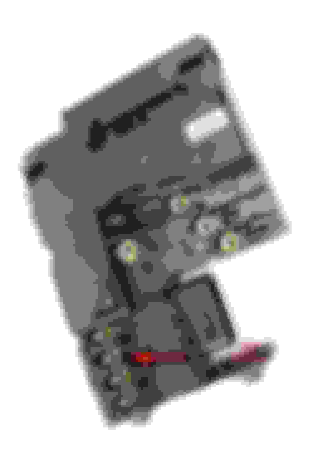
There are free connections on the battery box. Remove the battery box. The front cables are form-coded and fit (without violence) only in the right position.
Below are free connections. These are supplied by varistors. The picture is from my memory. Open the housing (when all nuts are removed, simply unclip the housing from the outside) and check again.
The connection is a M6 stud (1/4" fits)
Reassembly: Be careful when tightening the screws.M6 only 8Nm (5.9 ft/lbs) and M8 only 16Nm (11.8 ft/lbs)
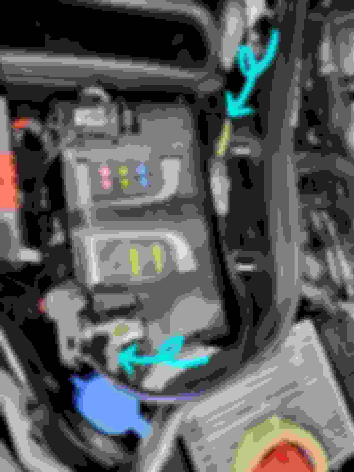
Cable entry: See the arrows. About here is a vacant passage.
I removed the fan inlet box. To do this, the rain cover above must be removed. That means removing the wiper arms. Remove 2 clips. Remove the rain shield at the bottom of the windshield vertically upwards.
Is clipped here on the whole width. It's very difficult at the beginning and you almost have to use big force. (do not lever over the windshield)
Since you have to remove everything inside anyway, you can perhaps save yourself the removal and push it through from the inside. With the battery box removed, it should work?
Info: there are cable ducts parallel to the sill and behind the seat.
Tip: Get some cable tape for outside.(As originally installed in Engine bay) And wrap the line like stock.
I successfully routed 4 gauge power cable from the passenger side footwell to the battery in the engine bay, without removing any components in the engine bay.
Direct wiring to the battery with 100 amp fuse 3 screws were the only things that were removed in the passenger footwell Had to puch out the rubber piece on the vacant grommet on the passenger side footwell
Very narrow passage which is barely visible Used thin wire to fish out the power wire Vacant rubber grommet on the upper right side of the passenger footwell
Last edited by MasterJohn; 07-26-2022 at 06:09 PM.
Recommendation:
Do not connect the amplifier directly to the battery post.
The GT has (normal today on cars) a battery management system.
Simplified description: The battery is only charged to 80%. When energy is released (e.g.: braking, pushing, downhill cruise control), this time is used to charge the battery with electricity. (would be maximum possible = 14.4V x 200A =2.9Kw)
The alternator is then switched off again and the battery is discharged to 80%. (A very smal mild-hybrid :-)) Save a little gas and emissions.
Unimportant consumers are also switched off, when the battery is deeply discharged. e.g. rear window-, mirror- seat- heating, sound system.
Info: This relay is also located in the battery module.
For this reasons there are sensors on both poles of the battery. There is also a current limiter on the positive pole.
He limits the maximum current of the expensive lithium battery.(Lifespan?) If you draw current here (I assume you mean a 100A fuse), this adds up.
I think it's better not to bypass these sensors. (Not tested) If you want to do so, connect the wire behind the sensor.
With the battery removed, you can also connect your cable to the battery module without removing it. Simply pry off the cover, then you get to the free connection.
And you save another 30" cable length. Here, for once, shorter is better. :-) :-) :-)
Question: Why only a 10A fuse? Which amp do you want to use? That would be nominally only 120W.
(Ignored the increased voltage drop due to the higher fuse resistance) A 4 Gauge wire = approx. 21mm� = 0.00091 Ohm/m at 5m 4 Gauge goes up to max. 80A fuse.
You could have tapped 10 A at the rear SAM without any problems. Is supplied with at least 2 x 6mm�. The 30A fuse for the subwoofer amplifier on the large 811 Burmester sound system is also located here.
Fun fakts:
810 sound system is specified as 650W. Fused with 30A. Theoretical max. power (without inertia) 12V x 30A = 360W 811 sound system is specified as 1000W.Fused with 2 x 30A. Theoretical max. power (without inertia) 12V x 60A = 720 W
In practice, these voltage and current values should not be reached and the real power should be even less.
Best regards
Stenzel
Last edited by Stenzel-Germany; 07-26-2022 at 04:48 PM.
Thanks again, Stenzel!
I had no clue about this battery regulating the charge level and limiting the power draw at both posts.
I was just lazy to remove the battery, because it had a strap and a bunch of unusual looking wires attached. Oh, the inline fuse I mentioned was 100AMP, not 10.
The power wire is not connected to anything yet, so I will try removing the battery and utilize the free connection on that conveniently regulated terminal post. Getting this done a little by little at a time.
I will continue to upload pictures of the progress!
Thank you again for your brilliant suggestion on getting the power cable from the vacant hole on the passenger side footwell to the engine bay. I cannot imagine removing wipers, rain panels, then the air duck. This will save hours and days on the install for everyone.
Just a warning about punching a hole in the main-cable rubber grommet/seal down in the passenger/left footwell ... be sure to re-seal it very well. I did this to run a pair of small wires for the added LiFPo dashcam batteries I added, thinking it would be OK for moisture as it's well buried. I was wrong. Ended up with some moisture-caused issues (flashing tunnel-located button-screens). I ended up sealing it with self-fusing silicone tape and it's been fine ever since. For reference, here's the product I used (a handy thing to keep "in stock"):


 05-02-2021, 03:22 PM