When you click on links to various merchants on this site and make a purchase, this can result in this site earning a commission. Affiliate programs and affiliations include, but are not limited to, the eBay Partner Network.
I been messing with my car for quite sometime now.
I have the pleasure of being assisted with capable aftermarket scanners and also MB Xentry clone version with a proper fast C4 interface.
What I have learned so far I want to share.
These are what you must get, in order to be able to troubleshoot properly and least mistake and more so if it is electrical or data bus gremlins which is a very complex beast if for our modules laden car. 01. MB WIS-EPC , without this wiring diagram and other good helping documents, you can forget trying to do anything more than a simple find-the-blown-fuse.
I got mine a long time ago EPC & WIS of 2018 from Ebay, I forgot where at Ebay. I then got from internet a WIS only no EPC, but of 2020.
I got another EPC-WIS copy when I got BenzNinja service but I dont use much because I don't like 15" small laptop screen.
02. By hook or crook, get a Xentry passthru version, with clone Chinese Open Port 2.0 interface, clone version good enough. US$30 ish I think now.
The hacked version software Xentry Passthru you can get for crazy cheap, if not for free. This is a free software from MB actually but you need to pay an hourly/per-day subscription* ( *if you are a qualified workshop ) to access MB server.
While this Xentry passthru with clone OpenPort is too slow and not suitable for logging the camshaft timing and hang/bricked quite often in my case, this is the only software where its
scan information is accurate. Accurate for modules names , DTCs and all the goodness of an MB official scanner software , as such this and the MB-WIS is then the best combo to have.
The learning curve to use MB WIS does take time, but learning takes effort.
One thing very good from MB WIS for most system are these OVERVIEW documents : Let's use HVAC as an example. Important creature comfort component.
These 3 documents, and with a DATA CARD you get when using any online MB VIN DECODER or a properly hacked complete EPC-WIS which has all cars Data Card built in, you now know what are the components your car model, option level and etc etc has for its complete HVAC system.
The overview is where you need to start at, not wiring diagram. I am attaching these 3 documents.
The wiring links are also on one of these documents and when used in MB WIS software environment/interface, all next documents are just 1 click away, no need to do individual search which MB WIS is kinda bad.
The document : Electrical Function schematic for automatic Air-Cond, ACTUATION
Will show you how the HVAC system works and who is the actual BOSS allowing the HVAC compressor to engage.
Will show you the complexity that the CAN BUS-es alone involved in HVAC operation is CAN L, CAN E or E1 and CAN B ....wow.
There you will learn that the big king kong engine cooling fan M4/7 is shared with HVAC system, now with the Xentry passthru software, you can even see how many percent of the current duty cycle for
cooling fan is demanded by engine cooling and HVAC cooling its condenser. Duty cycle or "level-of-power" the compressor is commanded by the ECM, yep ECM and not the N22/7 HVAC Computer.
When you read the Overview of the climate control system components you then realized that there are 2 interior ambient temperature sensors , one near steering wheel with round cover like a wire mesh,
and one at the overhead control panel where your light is and sunroof control. The sensors are all over the place and without these documents, if you attack the job blind, you will not be able to troubleshoot
properly till even 31st February, if such calendar date even exist
You then also realized that your front bumper located B14 outside air is part of the calculation/algo of the HVAC system.
You then also realized that there is such a thing called Solar Radiation Sensor. See Climate Control, Basic Function
There are so much information from these 3 documents, when you read them well......... you then are a better troubleshooter because you now know much better how all these components
are parts of the data input decision of the HVAC management/operation.
Go to MB WIS, there are so much information to assist us.
After that, you go and attack the wiring diagram.............. if needed.
Enjoy your troubleshooting.
================================
NEXT : What about use an aftermarket scanner instead of Xentry passthru ?
I will continue on that in a bit..............................
What about use an aftermarket scanner instead of Xentry passthru ?
Do remember, DO NOT 100% TRUST aftermarket scanner in the way they name modules or DTC description. Use 75% at best if scanner is a good one.
Even Xentry I trust at 99% only, because there are small errors in Xentry and MB WIS too but never really crazy ones which can lead you to wild chase.
Here I will show you that some aftermarket scanner for reason I do not know, over simplified the DTC information and can give you wrong modules name/ID. This is a TopDon unit for above video.
Go and watch it...............
This is the problem of that particular scanner which made Mr. Jake the guy in the video , who is a very capable diagnostician , but not familiar with MB cars or MB "speak" , and got misled by TopDon scanner using MB software version v10.34.
I believed TopDon and ThinkTool scanner uses the same MB software, originally from where.......? I don't know.
First the scan session : ECM DTC shown. The DTC for 1433, see that one.
Naturally one would go to the Tranny computer when ECM mentioned tranny selector level module has a mailfunction.
Here is where the wild goose chase started.
For reason unknown, TopDon only list N15/5 and not include A80 ISM, of which these do the same thing but differently and N15/5 is when the tranny selector lever is at the middle of the center console.
Jake was in an Uncle Murphy situation, because when he started working on this car, someone been in there and the center console is already messed with, as you can see below :
So, due to TopDon mentioning a N15/5 and only N15/5, Jake got so misled by TopDon DTC description....... he wasted hours trying to make sense of it and re-verify everything. You guys got to watch the video to appreciate it.
When I saw Jake assumed N15/5 is what he need to find, that is when I know this video will be a great one to watch from a perspective of someone VERY CAPABLE but being fed the wrong information by TopDon and
he is not familiar with MB cars while at it, very very Uncle Murphy situation.
Now, 2 days ago, Ivan of Pine Hollow was doing a GLE450 which he has fixed before, was a CAN BUS errors from water intrusion at the lift gate. Now it is no crank and lots of communication faults.
It so happened that Ivan has his ThinkTool scanner and this scanner is using MB software version 10.32 ( older )
This is why I have a gut feeling that ThinkTool is also using the same MB software as TopDon. Probably these two companies modify how the data is presented on the screen a bit differently.
But it seems the ThinkTool gave full proper description of 1433 DTC with the A80 ISM included.
If TopDon were doing the same, Jake would not have wasted so much time,
Autel has its own issue. Once I got a newer MB software update from Autel and suddenly there is 1 extra module, from usual and accurate 47 module, suddenly I got 48 modules hahaha.
I found out where Autel made that mistake, but imagine if it is your first time using this Autel at this stage of its MB software with problem and you never try using a Xentry, it will be a fun wild goose chase.
I have experienced a few bugs with Autel MB software, so no aftermarket is perfect. Overall if 1 scanner only to choose , I will go for Xentry passthru as lower cost version or the faster C4 as reccomended by BenzNinja and
with BenzNinja lifetime support while at it.
Launch has its quirks too.
It will not list LIN modules like a Xentry will, where in Launch the total modules will show 37 and in Xentry it willl show 37 CAN BUS ones and 10 of LIN ones.
Regardless that the LIN one are not listed in Launch full scan, when you go to each module , the LIN slave will be shown and you can do bidirectional on them.
For modules names and most importantly module ID, the closest accurate to Xentry naming them is Launch . It got almost 70% correct same ID as Xentry will call those modules.
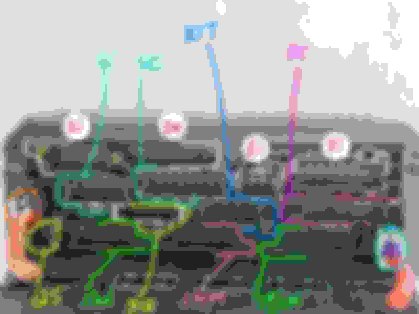
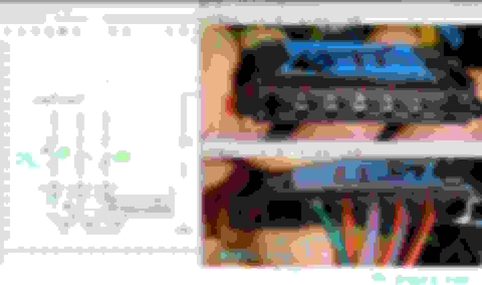
AUTEL : The pink ones are what Xentry call them as the module ID and the wiring diagram in WIS only uses modules ID and not names. Here is why I said, modules correct name/ID is IMPORTANT.
LAUNCH, some modules get correct module ID and some simply generic names only
Both Autel and Launch failed to ID Central GateWay module as N93 residing inside Front SAM, they simply call it CGW or Central Gate Way
CGW is also the name of another gateway called N93/7 Chassis Gate Way.
One can wait until 32nd of January, if such date exist to find wiring diagram of N93..... it does not exist as N93, it exist as N10/1 Front SAM.... LOL
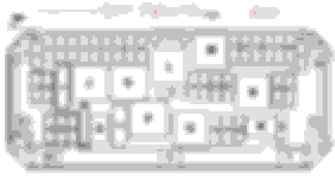
ABOVE DOCUMENT IS CALLED : COMPONENT DESCRIPTION OF FRONT SAM WITH FUSE AND RELAY MODULE
Now imagine using an aftermarket scanner and the car having problem with the N93 Central GateWay at Front SAM, while the car is also having N93/7 Chassis Gateway......
I wonder how would a tech without MB-WIS and zero MB experience and got mistaken N93/7 as the Central Gateway N93 and probing or replacing N93/7 instead of N93 of Front SAM ????
Initially I never knew in 2021 a N93 CGW is part of front SAM until someone in this forum told me and I read Front SAM COMPONENT DESCRIPTION
I been only reading Front SAM 10 pages of wiring diagram. I jumped too far DUGGGHHHH !!!!!
Allright, for today this is what I have to share........................
Last edited by S-Prihadi; Jul 11, 2023 at 12:20 PM.
Reason: add info
Remember these :
01. LOW VOLTAGE or LOSS OF VOLTAGE FOR A FEW SECONDS......WILL CAUSE LOTS OF DTC.
More so when ignition key is at ON position, no need engine running.
02. KNOW YOUR SCANNER data presentation after a full scan.
You must separate STORED DTC ( historical ) and CURRENT ( on going, Hard Fault ) in your mind.
Do not panic when seeing so many DTCs after a full scan.
This is a simulation I did once 2 years ago, and I did it again today now that I have Xentry, Autel and Launch scanners.
2 years ago I only have the dumb-azz iCarsoft MB V2.0 which you guys SHOULD NEVER BUY !!!!
I removed Relay J, while at car key in Ignition mode ( all warnings lights up or known as Ignition Key ON-Engine OFF aka KOEO )
I removed it for 10 seconds and install it back again, while still in KOEO mode.
Ignore the white strings , those are tied ( with mini hole drilled at fuse body safely) to the fuses, where those fuses are not easy to pull out due to their position haviing a wiper arm on top of it.
A pliers even a 90 degrees one also can not be used at that area, too narrow a space. On a Left-hand-Drive car the orientation of the fuse block will be reversed, my front side will be at your firewall,
as such you guys LHD cars have more room to pull out those fuses at firewall, a tiny bit more room.
With the relay J re-installed after 10 seconds removal, I turn off Ignition and cycle the ignition key twice ON-OFF-ON-OFF and then I full scan the car <<< this in green process will make all DTC's becoming a STORED or historical ones
and no more CURRENT or on-going fault DTCs.
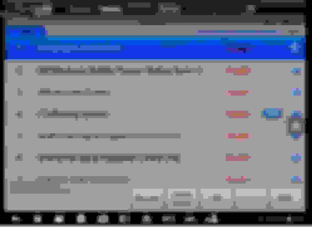
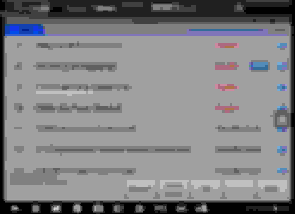
Now lets see how an Autel MS906BT will show the DTCs , where these DTCs are STORED or historical ones and not CURRENT or on-going Hard Fault.
So we have 10 modules with FAULT. and at a glance we do not know if they are STORED or CURRENT DTCs.
This is the low cost baby Launch Creader Elite for Benz ( only Benz, can't do other cars ).
Same with the LAUNCH , 10 modules with FAULT. and at a glance we do not know if they are STORED or CURRENT DTCs.
LAUNCH uses the termABNORMALand not FAULT
.
This is the Xentry, for this test I am using BenzNinja version with a very good C4 interface as it is faster. I have a video later to show you guys the scanning speed of these 3.
Now, this is where when one using aftermarket scanner may freak him out.
The initial display shown by Autel and Launch does not show which is STORED ( historical ) and which is CURRENT or on-going Hard Fault.
All you will see is 10 freakin' FAULTS .... sound scary yes ? Don't be.
Xentry on the other hand will show on-going Hard Fault with capital "F" and if STORED /Historical ones it shows small "f" or "i".
Some not critical fault, like my permanently disconnected LIN at the alternator , under ECM ( N3/10 ) DTC it will show small "f". You see alternator does not actually need the LIN which is a data connector from the ECM, where the ECM is the one making your car charging YoYo by intervention to alternator's built-in voltage regulator.
Alternator without LIN connected will revert back to its own built-in internal voltage regulator which is AWESOME for my case, a 200 amps Valeo I got. Superb charging as in NOT VIOLENT at all, very civilized charging profile.
So remember, always observe what are STORED DTC and what are CURRENT FAULTs.
******* If you have read this far and have seen Pine Hollow video on MB GL450, you would by now realized that Ivan initially thought it was CAN BUS issue on the GL450, while it was actually
a VERY low-battery voltage or intermittent loss of voltage causing all those CAN BUS communications DTCs **********
Now we shall see, how do modules "explain" faults conditions , what DTC they choose to use ?
Apology for Autel weird screen capture. My HDMI stand alone video recorder unit does not like Autel video signal.
Now let's focus on LOST of communication first : This is from the ECM N3/10.
U code is communication code, hence it is said THE MESSAGE IS MISSING. When power is lost to the control unit of the Transmission, that module can no more talk or broadcast its activity over CAN BUS.
You see CAN BUS in a car is not a talk-back system like a 2 person talking. CAN BUS system in a car is a broadcast system, all modules "speak/inform" of everything they are doing on the particular
CAN BUS channel they are at and other modules will only take-in the information needed and ignore what they do not need. So this is the ECM reporting as a DTC that tranny module has a malfunction.
Here is what we must understand, lost of power = loss of communication. Defective module can also stop broadcasting, hence ECM declared that tranny module has a malfunction.
This is why one must NOT BE alarmed when seeing MALFUNCTION , it does not always mean defective module.
I will list all DTC mentioning No CAN message or Lost Communication.
Will continue.....................................
Now we discuss CIRCUIT 15.
Still under the same test, removal of Relay J for 10 seconds and re-install it again while ignition status is KOEO aka Ignition Key-ON Engine OFF
In W212 and this would apply to all MB cars, they use German DIN for naming CIRCUITS or Power Supply wire/channel.
So above would explain what is Circuit 15.
DTC mentioning Circuit 15 can not be guaranteed that the description will target exact Circuit 15 or Circuit 15R ?
What you need to know is that Circuit 15 is a circuit or a powerline or a wire which carry +12V and is via a relay. That means it can be switched ON or OFF by Front SAM or Rear SAM computers.
So certain set of components are supplied by Circuit 15 or 15R.
Some sets of components are supplied by Circuit 87F or 87M, and this 87 is just another circuit like 15, but serve different components and hence it is called 87*
Imagine Circuit 15 and 87 families are like the circuit-breakers in your house electric panel, but they have the capability to be commanded to be ON of OFF by the computers inside Front or Rear SAM.
Since I removed Relay J, the loss of power at downstream fuses or loss of relay activation downstream is a lot and is a very good test.
Here when you see anything about power loss or failure of relay activation, this is what you must FIRST track down, and not the Lost-Communication.
Remember, loss of power or very low voltage = Lost-Communication too.
So attack the most upstream problem and not the downstream one.
Here is why I said : ******* If you have read this far and have seen Pine Hollow video on MB GL450, you would by now realized that Ivan initially thought it was CAN BUS issue on the GL450, while it was actually
a VERY low-battery voltage or intermittent loss of voltage causing all those CAN BUS communications DTCs **********
Let me show you :
See the green circle I marked above. That shows ESP has experienced very low voltage.
Since I know W212 well enough, the real power source of ESP in many cars is not from the Front SAM N10/1, but from a more upstream fuse block F32-PreFuse Block.
If a low power can occur this upstream, the downstream ones will also experienced the same. It is just a matter of what DTC database in inside those modules , is there a Low Voltage DTC or not ?
Also some modules do not trigger warning until the event duration is long enough or occurred enough times, and then DTC will be triggered.
I don't know all of MB DTC and modules DTC database, so I can't tell you what I do not know, but I can tell you what I know.
I have seen and recorded all DTC database of each and every modules in my car via Xentry, but I seen some actual DTC can appear and it is not in the database of the module as per Xentry.
Xentry is only the software, the modules are the true database keeper and some DTC it may not show when using Xentry to see its database, but that DTC can appear when the actual Fault condition is met.
So everyday is a learning for me and I am sharing with you guys so that you can bypass the tough learning curve faster.
See, terminal 30 is the same as Circuit 30. This means there is NO POWER or NO confirmation which some modules still uses hardwire +12V as confirmation from a more upstream module, usually a Front SAM or a Rear SAM.
Not all Circuit 30 into a module is for power, do remember that.
At a glance, it is not a surprise to first check the CAN BUS distributor near the door carpet, when and if one sees so many CAN BUS lost communication DTCs and this GL450 had CAN BUS issue when Ivan first fixed it like last year or so.
I tracked to the best of my ability all youtube channels doing Mercedes CAN BUS, because we need a good case study. We all must learn from someone......
As with anything related to electrical & mechanical and so on, we need to spend time to learn them, if we are not familiar with them.
Once you don't want to spend time learning, best to use your wallet power and choose a proper indie workshop or go to MB authorized.
Or you can do the super PARTS CANON salvo....... and waste your money
Now, about Mercedes Front SAM and Rear SAM wiring diagram, they are both 10 pages each so total 20 pages.
These two are not simple fuse boxes only but has SAM : Signal Acquisition Module, aka baby computers and some power output to certain devices do not use a fuse per se, but MB uses drivers to regulate
like dimming down or pulsing like PWM and diagnostic too. Its quite complex.
F32 prefuse box is much easier. Both SAMs are the power hub of your car.
Front SAM deals among others are with engine and tranny.
Rear SAM deals with ECO start stop and mainly creature comfort devices.
However since these two communicate with each other by CAN BUS-es, Rear SAM failure can make car dead too, depending on what went wrong.
I advice you guys to spend time BEFORE EVEN ANY TROUBLE happen to your car, so you learn while not under stress.
Take Front SAM and Rear SAM wiring diagram + all other supporting documents related to them as Tom Clancy novels for Jack Ryan, it is a very long story telling
These are the pointers :
01. Front SAM or Rear SAM pages are not actually interconnected like a super big diagram cut into smaller 10 sheets each...NO... that is not how MB does it.
02. You can't print all 10 pages and stitch them from sheet 1 to sheet 10 hoping it will be easier...NO. These pages some are different novel title so to speak.
03. Best is to use PC big screen and work in MB WIS/EPC software environment and not based on PDF, as the auto linking to other diagrams does not work when using PDF.
04. Having a 2nd screen is a good thing for 1 screen looking at PDF version of a diagram and the other screen is the MB WIS/EPC.
I shall give you example on the Relay J overall connections.
You will suffer first time tracking this relay connections, no kidding. You must see all 10 pages of Front SAM sheets to be able to find each and every connection linked to Relay J.
I have an excel file which I made as my own database for which sheet has what fuse numbers and what relays. This helped me a great deal, but it is a pain in the azz to make it.
Front and Ream SAM for W212 are ******, they serve each and every W212 variants and you need the Data Card to delete what data are NOT FOR YOUR CAR on those 10 + 10 pages of wiring.
We begin with Sheet 2. How do I know it is sheet 2 ? Well I looked at all 10 sheets already ....LOL.
Circut 30 or any line red and has a 30 , that means that is the most upstream +12V power at front SAM. There is only 1 of 30 for Front SAM operation. The 30z is a special case for gasoline ( diesel I don't know ) engine computer , see my explanation on previous post.
So circuit 30 is switched by Relay J and the output is then the Circuit 15. For this sheet 2, its shows this Circuit 15 feeds the Fuse 29 and Fuse 30.
This is how a relay pin number is in DIN standard.
85 and 86 is always the Coil, or in USA techy call it command wire or signal wire.
30 is always the POWER INPUT for this relay to deliver OUTPUT POWER +12V to components. This is based on car chassis/metal as ground or negative. I read some old cars uses car chassis as POSITIVE.
87 if a 4 pins relay or also exist 87A if a 5 pins relay, these 2 are OUTPUTs when relay is closed or energized or when not closed or energized. Its call Normally Closed or Normally Open scheme of the relay.
However for the green relay M or starter relay circuit 50, its pin 87 and 87A is different in function, very special relay.
See the green relay M case study here : https://mbworld.org/forums/e-class-w...illed-car.html Never never assume all relays if 5 pins are the same.
Now, sometime when the relay is the common 4 pin one, pin 30 and 87 can be used interchangeably , so do be-careful and never assume 30 is always the POWER INPUT, it can be pin 87 instead.
By wiring diagram and DIN standard, we must use pin 30 as POWER INPUT....but best to verify on the car itself using test light.
For coil activation, pin 85 and 86, there is no rule which is to be +12V and which is to be Ground or negative. I marked pin 85 as POSITIVE, as reference only for this post, I never bother to check it on my car.
Now we need to see, what else get power feed from Circuit 15 or Relay J ?
Again take a look at all other 9 pages/sheets and find Circuit 15 .... lots of work....YES.
Aha, we found 1 more. It is sheet 6.
See, Circuit 15 ( Relay J ) feeds power to Fuse 6 and Fuse 7 and that fuse 7 feeds power ( not signal ) to relay M the green special starter solenoid relay with diode at its OUTPUT pin.
If you take a closer look at Relay M compared to Relay J how it is drawn, you will notice what I labeled as pin 30 at Relay J is pin 87/87A for Relay M.
So, always verify the pin physical number on the relay itself and using test light at Front SAM to identify which pin gets the +12V as POWER INPUT , by DIN standard that pin with POWER INPUT is pin 30.
Anymore Circuit 15 ? Sure, find sheet 9.
See here, Circuit 15 is the signal wire to Relay R, not for power (pin 30 ) but to the coil 85/86. So this means, a dead Relay J will also take down relay R and not provide power feed (pin 30 ) to fuse 7 which is for Relay M power INPUT (pin 30 )
Since I done my homework , the Relay J overall duty is as I posted earlier :
This is what I have made for my own use, I am attaching them 3 files for you guys to be able to save hours and hours and without migraine.
01 and 02. Front SAM and Rear SAM relay tree and fuses served or powered by those relays.
Since these two fuse box + SAM are not custom to each car variant but are ******, you can use this for your car and make small adjustment based on your car options level and what engine models.
03. F32 Front Fuse box for my car is a B03 start stop option, so if your car is not a B03 and the F32 does not look like mine, you can not use my file. It won't be accurate.
PLENTY : Other important information/documents on Front and Rear SAM and F32.
I will not attached those 10 + 10 sheets wiring diagram for Front and Rear SAM. It is already all over this forum and most importantly those 10 + 10 sheets are best to be viewed in MB WIS/EPC software environment
for the auto link and the hundreds of other wiring diagram downstream of these files for each and every modules found on the car.
============================
Here is the comparison for speed and how DTC are displayed between 3 scanners in real time :
Autel MS906BT. Wireless bluetooth OBD2 VCI ( VCI = Vehicle Communication Interface )
Launch Creader Elite for Benz. Wired.
Xentry by BenzNinja with a very fast C4. Wired.
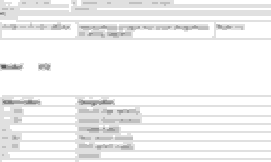
This is a good one, because the guy is using Xentry and MB OE wiring and being nice to explain everything, including his notes on the Ignition Key Switch Position with various circuit output.
The video above , highlighted the example that not everything is in Xentry documents for Circuit designation.
There is no 15C or 15X.
.
So, when our car is still healthy, it will be wise to scan and see what information you can get yourself be familiar with.
Probably MB engineers uses 15C and 15X as a way to indicate different stages of a +12V ( power ) being available.
As per Front SAM N10/1 and Rear SAM N10/2, they only provide Circuit 15 and 15R.
The N73 Ignition lock control unit EZS itself get power from Circuit 30z like Engine Computer, which is fuse 27 and is always ON/HOT with special wire and fuse from F32 pre-fuse box. VIP power line so to speak.
So when a key FOB is merely inserted, or position A as per the youtube screen capture , the so called Circuit 15C is activated.
Honestly, I have not traced what is actually a Circuit 15C is ( too much work ) , but if car was in DEEP SLEEP, the K2 relay at F32 Prefuse block would be awaken the moment you open the car door.
*********
When the key is turned 1 click or position B, this is when accessories like cigarette light is now having power, Circuit 15R is activated too. So now it is 15R and 15C.
With circuit 15R activated, that is Relay K which is activated, we then have power to these modules :
At the Rear SAM N10/2, there are 3 groups of Circuit 15R They are 15R, 15R1 and 15R2 where the designation of R1 and R2 you can only see in the Rear SAM wiring diagram 10 sheets..
In the Rear Sam fuse assignment, they will only show you Circuit 15R, All are for amenities like cigarette socket and USB only. With one very IMPORTANT one : Fuse 37
************************
When the key is turned 2 clicks or position C , Circuit 15 and Circuit 15X is powered. I do not know what actually a circuit 15X is , but we know what Circuit 15 is. It is Relay J.
This means Relay J is the one activated, as this relay output is what becomes Circuit 15. Hence the power available to modules are as below : Circuit 87M & 87F is also getting power.
The Rear SAM N10/2 will also be powering its Circuit 15, based on the car options level.
Next final click of the switch is engine will be cranking and alive. That is when Relay M for starter solenoid will be energized to create a Circuit 50.
So, when you have issues engine can't crank and no DTC, you can see better using a Xentry of any proper aftermarket scanner the status of the Circuit 15s stage by stage, if say the green relay M is not the culprit.
.
Last edited by S-Prihadi; Jul 15, 2023 at 04:32 AM.
01. Another learn from others. Learn TO BE CAREFUL with non MB OE wiring.
02. Be aware that W212 has gone thru a face-lift in 2014 and the CAN BUS get modified too.
03. Always decode your VIN first for its Data Card, before you tackle any wiring troubleshooting, because the Data Card is the only way you can tell what options/module you have on your car and use the
proper wiring diagram based on that information.
Summary : But you must watch the video in full first.
- Techy used the wrong CAN BUS wiring diagram and could not find the culprit, until he done more physical testing and realized the issue.
- Techy did not realize for face-lift model which is MY 2014, the headlight CAN BUS is now E2.
- E2 is also the CAN BUS used by A1 Instrument Cluster in face-lift model 2014 and up.
================
2013 and older = Pre-facelift
2014 and up is Facelift
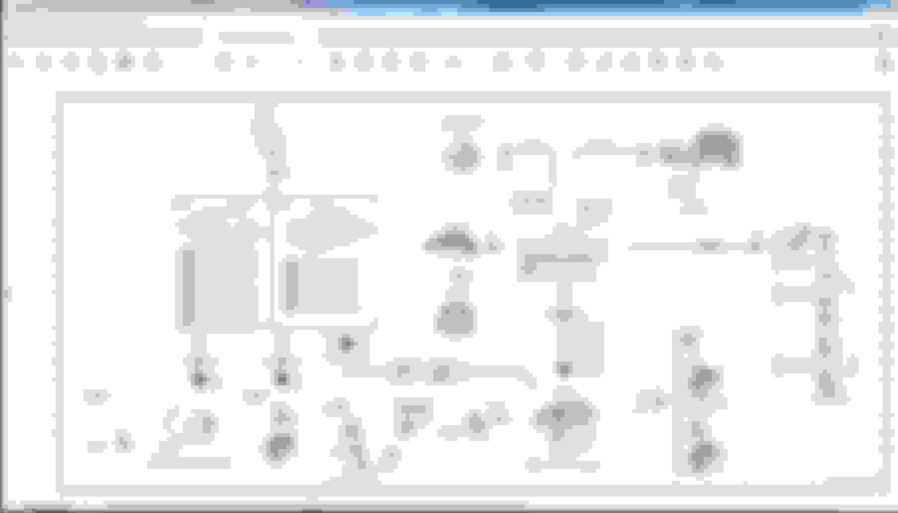
The A1 Instrument Cluster wiring diagram, showing the CAN E2 in use by 2014, and also CAN B since day 1 to end of W212 production.
Headlights of W212, before face-lift :
CAN G was for the headlight before face-lift , so short circuit of headlight even up to its CAN module being shorted, will not take down CAN E ( or E1 ) of A1 instrument cluster.
******
W212 face-lift headlights :
So read read and read, know your car well ahead before you have troubles to solve.
Last edited by S-Prihadi; Jul 15, 2023 at 03:34 AM.
I am attaching an A2 size Front SAM schematic, all 10 pages.
Why A2 size ?, so that you guys do not loose track of the wire connection when using A4 or Letter size print which will split the schematic up to 5 pages.
In WIS, the schematic is non-cut and has legend at the right side and can auto link to other schematcs and can do search, but it CAN NOT search small connector like those at FRONT SAM. If connector not in Blue (link), you can't search them
See below :
I am also attaching a JPEG high quality image of all 10 Front SAM schematic, surely no legend, just schematic. My old one was not HQ enough as such small text is not clear.
What for ?
JPEG is the best for speed reading. I am messing with all connectors of my Front SAM and this JPEG save me lots of time as we can move to next "image/schematic" with ease.
Unlike PDF where you can't do speed switching between 10 schematic using mouse wheel..
Remember : Front SAM 10 pages are not big schematic split into 10. Each one has its own story-line and purpose, as such sometimes we need to see all 10 pages to find a connector pins....I am not kidding you !!!
I give you an example : Connector 3M of Front SAM
Notice that I stated 3 sheets involved in showing all the wires/pins to this simple 5 active pins of a 7 way connector.
The left schematic is from my engine computer. Where I have information on pin 3, 5 and 6 only. I then search all 10 Front SAM sheet/schematics to find pin 2 is at sheet 3 and pin 4 at sheet 6.
I am interested at connector 3M of Front SAM because those 3 are for my engine computers and is commonly used for engine computers those Fuse 22, 23 and 24.
Please help! I have the same errors as you have in the scanner. No errors on Instrument cluster just in scanner. The only problem in my w212 e250 2014 is the car starts late after I have given a single crank .
please help.
Both batteries are fully charged.
Can bus checked under carpet
Please help! I have the same errors as you have in the scanner. No errors on Instrument cluster just in scanner. The only problem in my w212 e250 2014 is the car starts late after I have given a single crank .
please help.
Both batteries are fully charged.
Can bus checked under carpet
01. What do you mean by : I have the same errors as you have in the scanner.
02. What DTC and explanation are you having on your scanner and what scanner model are you using ?
My mechanic cleared the codes several times and the codes come back again and again in no time.
the errors come back when I start the car and it starts late. The problem is when I put the key in and give the car crank no crank happens then I wait for few seconds the car start itself. Sort of delay.
Is that causing these errors if yes how to fix that problem!
Well ,usually this kind of issues of LOST OF COMMUNICATION,U code is from BAD WIRING or BAD/LOOSE CONTACTS causing very low voltage during crank. Cranking need 200+ amps you see.
So your modules loose communications to many other modules, hence the DTC said so.
STORED means the DTC is no more, CURRENT or ACTIVE is what we worry.
So when engine running, battery voltage no more dip down, modules recover and the DTC becomes STORED, because your modules started to be able to communicate again.
Also is the main battery healthy or not ?
==============
Slight delay of actual engine cranking vs key crank can also mean starter solenoid a bit stuck. Are you on push button start or normal key?
I saw your video.
The delay between you use the key to crank till engine started cranking is CRAZY long at approx 55 seconds !!!
01. Since I do not know anything about how MB diesel works for the diesel heater circuit, your cool 12.5C ambient temperature we keep at the back of our mind as far as any delay it may cause to
starting an engine.
Now, remember that our W212 is not an old analog starter system.
It is a computer controlled starter. So when you command engine to start by key to maximum clockwise ( crank ), the computer can delay it all it likes, but I agree your delay is way too long.
02. Since there is a transmission STORED DTC and also A80 ISM shift module, which these two modules when they are not ready, will not allow your engine to start.
When did this issue started ? Any trigger/cause you can remember ?
Basically : You need someone who knows how OM651 works and how the W212 typical modules/computers involved in the engine starting works with each other to give the final OK...and then allows
engine starting to occur. The person need to be a good diagnostician who can see data/commands between the modules. Also there could be a need for scope to see the CAN BUS activity.
Next test I can suggest, is to use your engine built in volt and amperage meter at the instrument cluster to see electrically what is the voltage at :
- first key into ignition
- 1 click to the right ( accesories )
- 2nd click to the right, Ignition ON, engine stand by
-3rd click is CRANK engine and see during the 50ish seconds delay, what is happening voltage wise to the battery.
To turn on the voltage and amperage at the Instrument Cluster, watch this :
Video it happening like how you video the CRANK delay and post it here.
If you dont want your current utube channel to be seen in public, make a new account and upload it there and share with us
ADDED :
For next test, turn off the ECO mode please.
Last edited by S-Prihadi; Jan 18, 2024 at 10:17 AM.
Trying turning off the eco several times! The result is same. One more thing! This usually happens when the car is sitting cold overnight and when I try in morning this happens! But when I have driven it or is hot it starts normally in just a single click
Trying turning off the eco several times! The result is same. One more thing! This usually happens when the car is sitting cold overnight and when I try in morning this happens! But when I have driven it or is hot it starts normally in just a single click
Checked the relays in front sam by disconnecting and having a look. Everything looks fine and my mechanic even tried exchanging the J relay with another Merc J relay which was at his garage on my saying!
Relay can not be tested by looking, it has to be load tested at least to 10 amps.
These are the relays which can PROHIBIT engine start, biggest suspect Relay R and M, if you are sure relay J is good.
DO NOT SWAP the special green starter relay M with any other relay. It is unique in its internal wiring and voltage spike protection for the engine computer.
Also please check the undocumented ground cable under the car I call W-TF is tight and clean and make sure W10 battery ground to suspension strut is clean and tight.
Read here : https://mbworld.org/forums/e-class-w...ital-wire.html
Mercedes SLR McLaren 722 S Is Extremely Rare Example Modified by McLaren
Slideshow: A one-of-one U.S.-spec Mercedes-Benz SLR McLaren Roadster became even rarer after a factory-backed transformation at McLaren's headquarters.


 I jumped too far DUGGGHHHH !!!!!


 , you can use this for your car and make small adjustment based on your car options level and what engine models.


 , but we know what Circuit 15 is. It is Relay J.