When you click on links to various merchants on this site and make a purchase, this can result in this site earning a commission. Affiliate programs and affiliations include, but are not limited to, the eBay Partner Network.
- I need to replace 2 DIFF bushing and 1 DIFF mount.
- Replace all 4 subframe bushings.
- 2 suspension arms while I am in there........
And dumb azz me, I forgot to buy DIFF shaft seal ahead of time ...DUGGHH !!!!
I forgot that DIFF removal means drive shaft removal too and will best be using new shaft seals, item 100.
Item 80 is plastic, so it has to be replaced.
And WIS said I must replace item 50.... I wonder why, the last time the DIFF is out ( install ABT differential inside my DIFF ) , item 50 was not replaced.
Item 30 is insurance only, just in case I twist it by accident
-----------------
This is a first time I seen what I think as baby mice sh-it on my car , under body long sound/heat shield....or any part of my car for that matter.
The gap to car body from this hairy sound/heart shield is so small/narrrow , why would it took a dump there ?
This took place surely no more than 3 weeks ago, or less...maybe while I was a week in Bali ???
.
------
Anyway, exhaust system 50% of the rear has to be removed. I can do it solo with my mini jacks on trolley and lashing rope.
Must first remove both mufflers tips.
Support all 3 mufflers
.
Squeeze in both rear mufflers using lashing belt, because they will not be able to come down due to its cavity design.
Without lashing the muffler will hit the screw in green arrow. If 2 person helping you, it is easy, they can use muscle power to push both rear mufflers inward. I am doing it solo.
.
.
If someone is at the front muffler preventing scrubbing of the gasket, it will be better.
This is my 2nd time I removed this 50% rear exhaust system solo.
Below shiny ring is the gasket
Un-even length between left and right pipes, yep. Don't ask me why only a single gasket , I too don't know why.
Long pipe is for the shiny gasket.
-----------
Remove propeller shaft.
I wonder why the heck MB made the "dick" of this propeller shaft adapter at DIFF so long. 60% of it is enough already. It makes removing propeller shaft not elegant, I mean must use
force and the force is towards the middle bearing.
There is already a protruding female receiver for the dick....., thus no need dick to be that long. What a **** design
------
Remove all suspension arms for RIGHT rear, so that I can pull out drive shaft/axle.
.
.
I am tired...........
I take my own sweet time...no rush.....
Managed to remove the DIFF today, blo-ody hell, it is 34 kg / 75 lbs, I thought only 20ish kg..
I was afraid it falls and smash my face you see.
Right rear drive shaft removed. Minimum 1 drive shaft have to be removed.
Treat the drive shaft with love and respect.
.
My Toyota Jack pad adapter for cushion of the oil sealing region of the drive shaft.
.
------------
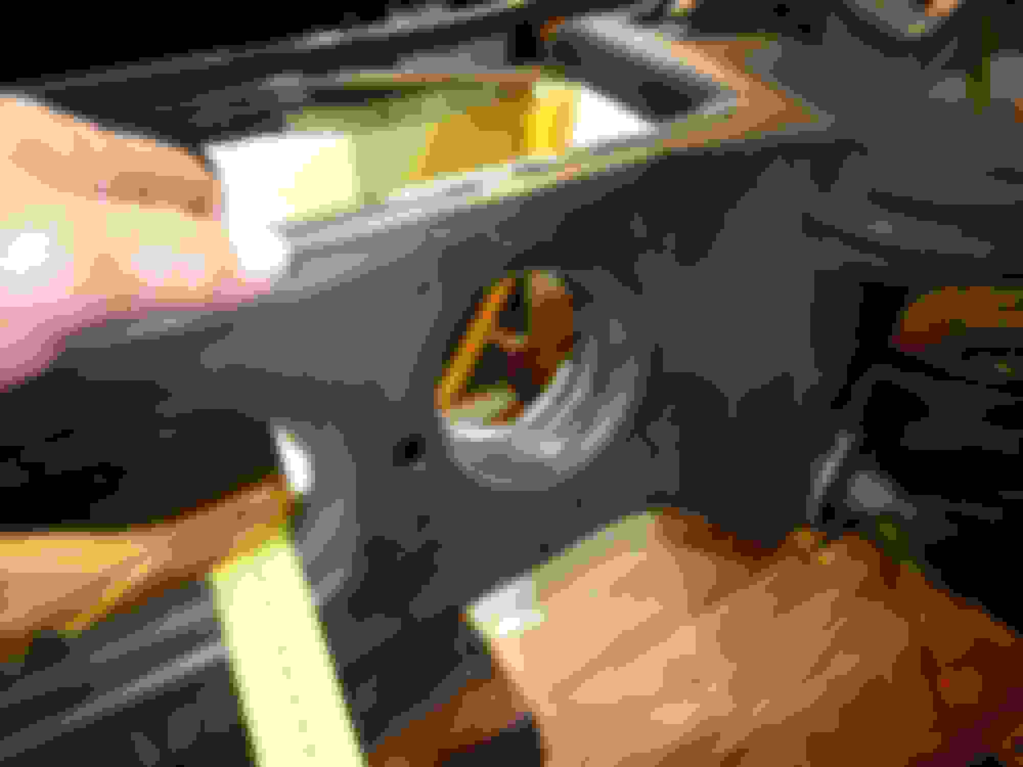
Clean right side shaft seal region at DIFF
Close hole of right drive shaft at DIFF, cleanliness is everything.
.
.
---------
Now I must tie down the DIFF as best I could because I need to swing it to the right side by 4-5 inches to remove the LEFT drive shaft...when all 3 mounting bolts of DIFF been removed.
Here is the beauty of the bike jack on trolley
.
I really fear DIFF may fall off when moved, while thinking it is 20kg ish.
The rear DIFF mount bolt removed .
Loosen both bigger bolts at bushing DIFF and took one only out. Test mini jack on trolley for stability by shake test, so far so good.
Pry out slowly LEFT drive shaft.
Working room very tight. The DIFF can only move to the right just nice to clear the shaft end towards seal. I do not want to damage the seal/
Here a 2nd person will be nice while I protect DIFF seal from drive shaft end, while DIFF can be moved slowly to the right.
Doing all these solo and while lying down on the mechanic bodyboard is no fun, my agility is limited and my viewing angle is limited too.
Wheewwwww....made it.
Guess what, here I realized how heavy the DIFF is when I tried to lift it up while my body is still under the car... NO CAN'T DO.
Got to call my male servant to help me lift it up and down to wooden trolley...... I fear my back-pain may get whacked. I don't have power when sitting down to carry this kind of weight.
Standing up I can carry it to the weighing scale, no problem but I still do not want my back-pain to come back. 36kg with trolley. Trolley max is 2kg only.
Oh oh.........I do not have the special tool to remove the parking brake "joint".
Pliers wont work........ duggghh.
.
.
.
.
.
.
.
I googled MB special tools P/N because the drawing of the left side special tool does not make sense, the ending 63 00.
Aha, so that is how the supposed tool would look like
Amazon USA has it, but it will be 10-14 days as soonest, I can't wait that long.
I then DIY the tool........ The mini shaft/rod is from one of my Dremel sandpaper shaft.
.
.
Must file some sort of hook, otherwise the mini shaft wont grip......
I still needed to add vinly tape and cable tie as "grip" point for the Knipex original "teeth".
Success !!!
.
DONE. simple but annoying.
The small black rubber insert is there to prevent two cable ends from being out of their parking space.
.
------------
Preparing LEFT side for subframe lowering tomorrow.
1 of ABS wheel speed sensor and 1 of headlight level sensor. Disconnected.
.
Clean clean clean....must work clean. Connector bulkhead side.
Damper un-bolted. Tomorrow I will need to strip naked stip the trunk to remove the damper at top mount. I hate doing the trunk liner.
Custom Rear Subframe craddle on stand-bye for tomorrow....
Let see how well it works now that there is no DIFF on rear subframe.
.
I made this in 2023 .......... Hope it will work well tomorrow
"Houston, Tranquility Base here. The Eagle has landed".............
Learnt a few things......
01. Due to RIGHT side has no drive shaft and brake rotor and knuckle, it is lighter by at least 20kg. So the subframe becomes un-balanced.
Must use string to tie dow RIGHT side. I did lash the middle of the subframe with those racheting tie-down belt, this helps a great deal as main
holder, but not good enough to balance the subframe equally.
02. Due to 01, I must prepare holes on wood craddle for string to be able to become tie-down facility.
03. Height clearance calculation of craddle and trolley is perfect, I have decent room to clear the subframe, but since Quick Jack height increase from level 1 ( middle ) to maximum
is also making the car move backward, a second eye from my male servant was needed, unless I want to raise it slowy and peek and raise and peek or car can touch subframe.
My male servant is assisting me today....nice.
Rule no 1 for me when working is make the component as clean as possible fiirst. So my male servant is doing the subframe washing hehehehehh.
Do you know Durex made XXXXL size condom ?
Protection under the condom....
==============
The DIFF bushings is way more troublesome to replace then the front and back subframe bushings.
DIFF bushings are ALU body very inteference fit to steel subframe as usual, while subframe bushing is rubber to steel inteference fit....easy to do...as long as we have the proper tool.
The yellow steel color, left side , the static U shaped cup is from the Subframe Bushing Tool kit, I need it due to my Vevor bushing tool kit does not have anything bigger than 80mm OD.
.
This one :
Scratch protection for my subframe paint. 1mm PU sheet x 2 layers. And a few layers of white vinly tape.
.
.
.
.
The subframe at DIFF bushing region is not a 100% flat surface like say a glass, thus you can see the pressure points is not the same for the U shaped steel cup.
The bottom PU layer get cut, the top PU layer is only squeezed bad.
It is two steel plate shaped and welded to become one, it seems based on all the bushings I have removed on subframe.
Always this gap at all bushings bore hole
.
Above is RIGHT side DIFF bushing bore.
The LEFT side DIFF bushing region is worse than RIGHT side, in terms of steel plate flatness.
My push pipe keep sliding off, meaning the other end is not very flat and the bolt is then angled.
Below is LEFT side DIFF bushing bore.
INSTALL BUSHING........
I had to make and use a DIY ALU plate to spread the pushing load better for LEFT side, right side no need.
.
.
DONE both DIFF bushings new ones installed.
.
.
----------------------
Crappy instruction 1 single piece, 1/2 of A4 size...WTF
I can't even tell which component is on the photos are actually being used where... I mean the 4 smaller U shape cups.
.
They got numbers on each and every component and yet they do not use it as assisting instruction.....
Sorry, the RIGHT rear subframe bushing bore hole, I forgot to take photo. Will take photo when on the LEFT side one.
----------------
My subframe bushing toll kit can be safer or better to use, if and when the bushings are DEAD stuck, by trimming the bushing side a bit, so that the footing of the tool
is of more surface area and less stress to the steel plate of the subframe. See below :
The bushing bore hole.............
Next, Install new rear suframe bushing
Protect subframe paint.
Use silicone grease as sliding agent.
.
MB reccomended sliding agent/lubricant.
--------------
FRONT SUBFRAME BUSHING
Very small footing area for the tool feet. I keep away from open end, because it is least strongest.
The corner is good , two metal sheet support.
.
.
.
.
.
.
.
New one INSTALLED. Front subframe bushing.
I forgot to add. The REAR subframe bushing has direction too. You can see it from under side, so I made an arrow at top side too.
We can tell that the hole at the steel is elongated towards East-West, front as NORTH.
is this a modern adaptation of the ship of theseus? the mercedes of prihadi?
you definitely are resourceful and have quite the time to take so much care of your car.
wow! keep it up
is this a modern adaptation of the ship of theseus? the mercedes of prihadi?
you definitely are resourceful and have quite the time to take so much care of your car.
wow! keep it up
Got interrupted last week.
Had to help a client , he paid me to inspect 80 footer yacht pre-owned in Singapore.
Make some quick bucks while having fun.
Superbly maintained yacht, amazing. Original owner MONEY NO OBJECT kind of maintenance, I love when yacht owner is this category.
Floating dock...damn, crazy expensive to hire a floating dock.
See the shiny coating on the propeller, that is one amazing barnacle free coating which can withstand propeller spinning in a water...I love this coating.
16V 2000 M90 MTU 1,800HP x 2
.
---------------------
Got back in country late last week and my indie who has been sick, needed my help to troubleshoot parasitic drain on a 2018 Range Rover L405, 3.0 super charged petrol.
So I spent Friday and Saturday troubleshooting a Range Rover, which I do not even have the wiring diagram.
There is no data card ( build sheet ) like our MBs we can access openly/easily.
Dumb-azz design.
Can you believe that the fuse box, which is similar to our Front SAM, is hidden so deep under the wiper plastic cowling, if I want to access the fuse
propely, I need to remove the wiper and then the plastic cowling...DUGHHHh !!!!!
Lift up partially the wiper plastic cowling ( me do not want to remove wipers ), so crude....only then we can access the fuse box.
I never went as far as fuses and relays, I first wanted to know its DEEP sleep mode current.
.
Anyway, problem solved and a unique cause. I will share next time in a different post , which our W212 could actually behave the same too under similar circumstances.
-------------------
Got a sore throat and a mild flu, I hope tomorrow I can continue the subframe bushings works.
Damn, my memory cell is so bad, I forgot where I put two new rear suspension arms
Everytime I went out of town or out of country and lost the working momentum.....I forgot many things.
Searched today an hour for the suspension arms and I could not find it, dang...they are big not small.
Anyway, progress today :
Both front and rear subframe bushings of LEFT side has been renewed.
THE REAR ONES
THE FRONT ONES
The DIFF rear mount
.
The DIFF rear mount is very metal, I mean very little rubber vs metal ratio.
Installation must wait till I get DIFF in place.
-------------------
Install REAR subframe bushing.
Below : Rear bushing cavity is cleaner than front bushing cavity. I already cleaned it though.
=============
Front bushing cavity, before cleaning
After cleaning.........
Front bushing installed
.
==============
Took me an hour and a good headache cleaning the car chassis covered by the rear-subframe.
Albeit I am on a mechanic body-board* ( *whatever the name is ), my neck hurts having to raise high so long.
Revenge time, replacing the blue plastic fuel hose which needs fuel tank to be dropped down 2 inches.
Above and below, these two small bolts secured the fuel tank to the car body, so not only the metal strap under the tank.
Damn, originally the two stud is centered. I remembered I tightened today to 20Nm ( the spec ), these two stud is not this center !!!! I am off like 3mm somewhere.
Must re-do again tomorrow...dughhh !!!!
I am pulling out the old one, with balloon protection ( spill prevention ).
Good thing I have marked RIDE HEIGHT on other arms.
So all I got to do is lift up the wheel carrier ( wheel knuckle ) till the white marks aligned
.
All bolts and nuts were cleaned/chased, so nice to have thread chaser kit.
.
.
----------------------------
Subframe back in place, I did it solo. The DIY craddle and the bike jacks is and awesome set. All bolted, but not torqued yet. Front bushing small plate on purpose not installed yet.
.
.
I DIY a new tool today.
MB has special tool to squeeze front portion of the parking brake cable nylon tip latches, so that the 2 latch will shrink inward and you can then remove.
The tool is below :
.
Using pliers is a bi-etch if the other latch is at the top.
Socket M12 is a bit too big, M11 is too small.
M12 with some vinly tape can work
.
Left parking brake cable must be removed from its locked spot, when we want to join it to the MAIN PULL CABLE, because we need it to be very angled
when the cable crimped end-stop, enters the MAIN PULL CABLE interconnect.
.
============
I should have tightened this DIFF mount before mounting the subframe to the car, the working room is a nightmare.
I was hoping to get the zero degree when suframe already mounted to the car.
First I use 4kg of diver lead weight, hoping the DIFF mount will zero itself.
But in the end I use water level assist too.
DIFF installlation. My driver was assisting me, I can't do it alone, the aiming and shaft insertion is not easy if from a single person view, blocked by the DIFF itself.
This time I raised the car maximum height for DIFF install, but was as mid-height when I removed the DIFF.
Blo-ody hell, I am short of 2cm extra height , hence the wood on the trolley wheels.
The bolt torque data for the DIFF is not complete, you must use other separate document.
In red is what the WIS for DIFF install-removal did not include,
.
It is here :
.
Bolt 5, 65Nm for E12 Torx is the highest I ever seen on W212. Usually E12 Torx size in W212 are much lower , most are under 30Nm. But the bolt thread is 10 millimeter OD size, which is strong.
All 4 subframe main bolts torqued and using new bolts because the special thread locker on the new bolt.
The female thread bores on car body already cleaned/chased.
Small bore for front bushing plate
.
This plate
-
.
Of the 4, the RIGHT REAR has the highest "friction" when tightened.
At first I thought it was the dry thread locker on MB new bolts or I perhaps I did not clean/chased enough this particular female bore thread.
But maybe it was somehing else............ like micro mis-alignment of forward-rear, the hole of the bushing has room for left and right allowance only.
---------
This is how the bolt was by position as per 2014 to before I replaced the bushing and new bolt. This photo was taken when I was measuring the chassis some months ago.
Only Right Rear below : See from different angle
New bushing and bolt, today.
White arrow is FRONT of the car.
I added ALU tape to close the opening of subframe front bushing, which always stored road dirt.
Before ALU tape added.
ALU tape, dirt protection.
,
There are water drain holes at the bottom, so no worry.
-------------------
RIGHT side drive shaft already IN.
.
Anti corrossion protection for magnetic tone ring and shaft end.
.
.
Under 500 miles 2nd hand ( accident car ) wheel carrier complete with bearing from Germany.
I bought it for fun and I best use it. So like new...damn !!! I am so pleased.
Mercedes SLR McLaren 722 S Is Extremely Rare Example Modified by McLaren
Slideshow: A one-of-one U.S.-spec Mercedes-Benz SLR McLaren Roadster became even rarer after a factory-backed transformation at McLaren's headquarters.


 , under body long sound/heat shield....or any part of my car for that matter.


 , I too don't know why.


 , while thinking it is 20kg ish.


 .
.


