


Understanding Intercooling, Charge-Coolers, Heat Exchangers and Circulation Pumps
Subscribe
Quote:
Think what it must have been like to writeOriginally Posted by kingnash
gawd... so much reading
For anyone wondering what happened to my charge cooler project, its all installed and I've been driving around a lot over the last few weeks, but I'm struggling to find time to write it all up. I've got lots of procedures and pictures, and I'll post it up next weekend. I'll cut to the chase though - here are the quick answers:
Does it work? YES
Are there any downsides? NO.
See ya soon, Nick
Does it work? YES
Are there any downsides? NO.
See ya soon, Nick
Here's a concise procedure for fitting the BMW radiator and pump:
Drain the IC system and remove the pump and HE.
Buy a new BMW X3 radiator and cut off all the brackets and ribs.
Shorten the inlet & outlet to leave a single swage, and trim swage back to 1mm high.
Cut back the HE top stiffener to clear the safety catch.
Cut slots into the HE top stiffener to mount the ABC cooler (like AC condenser).
Flatten the ABC cooler bracket and bolt through the HE.
Bolt the ABC cooler outlet pipe bracket through the HE.
Cut and bend the top rail to clear the HE header tanks and ABC cooler
Lower the ABC cooler outlet pipe bracket by �” and route through the headlight bracket.
Move the safety catch �” forwards so the tang clears the HE.
Move the ABC thermostat, pipes and brackets �” to the left (tricky but critical).
Bend or shim the engine oil cooler �” forwards to clear the HE.
Move the forward fasteners on the forward under-tray back �”.
Move the RHS horn up �” to clear the larger pump.
Cut away the LHS radiator bracket to clear the HE inlet.
I cut the RHS radiator bracket back, but this probably isn’t necessary.
Cut away the RHS headlight bracket to clear the HE outlet (though not this much).
The Pierburg CWA 200 pump faces backwards so the outlet faces upwards.
Cut and drill a new pump mounting plate to go directly on the rad.
The CWA 200 pump needs its own, larger mounting plate.
The CWA 50 & 100 pumps can probably use the stock mount & orientation.
Raise the Pierburg pump so the electrical connector clears the radiator bracket.
Connect the pump and HE to the stock plumbing using appropriate reducing elbows.
Trim the radiator intake ducting to clear the additional and relocated plumbing.
Fit IC thermostat to RHS IC outlet pipe.
Wire pump controller to battery, pump, ignition and temp sensor.
I'm going to post lots of pictures of what I did, but rather than spending a lot of time on photo hosting, I'm going to upload directly, one picture per post, so I can describe it OK.
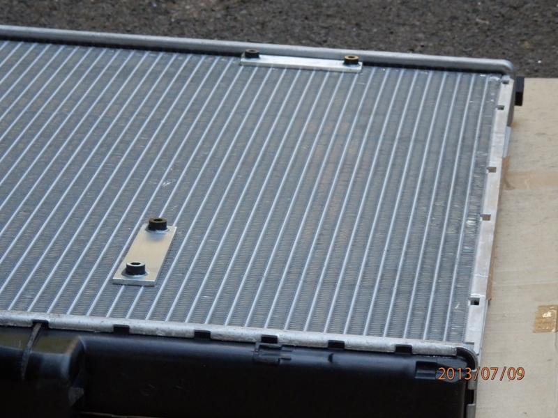
Here's the first. In order to mount the ABC cooler and pipe brackets to the new HE, I made some new brackets on the reverse side, to which I glued some bolts that go through holes pushed through the HE matrix.
Here's the first. In order to mount the ABC cooler and pipe brackets to the new HE, I made some new brackets on the reverse side, to which I glued some bolts that go through holes pushed through the HE matrix.
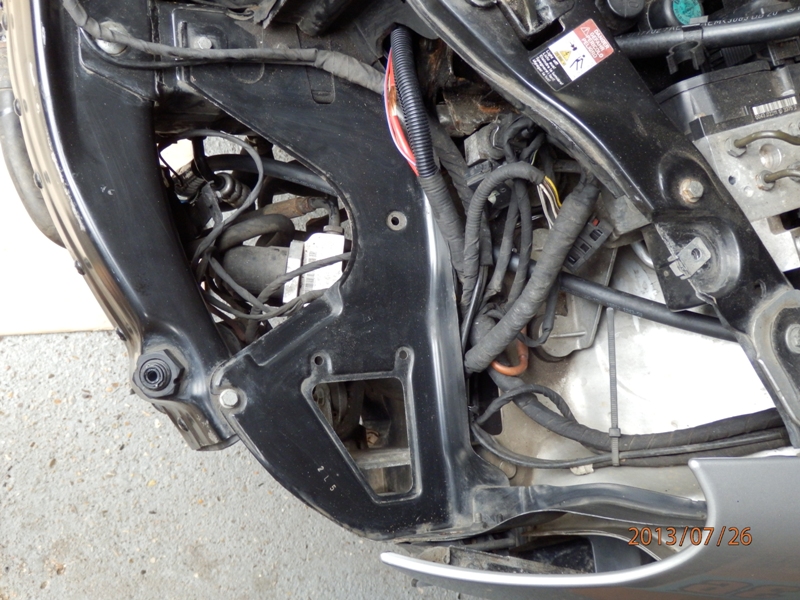
I cut a section out of the right hand side headlight mounting bracket to clear the HE water outlet. Sorry, I can't give any dimensions - you'd just have to go by this picture, though I did cut out about 1cm more than I needed to on each side.

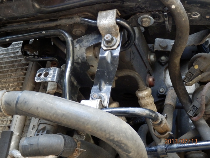
I moved the elaborate bracket the supports the ABC thermostat and various pipe backets to the left (as seen by a seated driver). I did this by drilling new holes in the bracket mountings. This is one of the key operations, and has to be done at the point of maximum disassembly. The bracket is VERY fiddly to remove, but it can done if you loosen everything else. The bracket mounts to the impact bar and to the left hand radiator support bracket. The latter is removed in this picture for clarity. When fitted, its damn near invisible. In hindsight it would have been better if I had moved the bracket ONE INCH to the left.
MB World Stories
The Best of Mercedes & AMG
Explore

6 Mercedes Models That Did NOT Age Well (But Are Somehow Still Cool)
Verdad Gallardo
Manual Mercedes? 6 Times Sindelfingen Let Drivers Have All The Fun
Verdad Gallardo
Mercedes SLR McLaren 722 S Is Extremely Rare Example Modified by McLaren
Verdad Gallardo
8 Classic Boxy Mercedes Designs That Have Aged Like Fine Wine
Verdad Gallardo
Flawlessly Restored Mercedes 190E Evo II Heads to Auction
Verdad Gallardo
Electric Mercedes C-Class Unveiled: 11 Things You Need to Know
Verdad Gallardo
Mercedes EQS Gets A Major Update: Everything You Need to Know
Verdad Gallardo
5 Underrated Mercedes-Benz Models That Don't Get the Love They Deserve
Verdad Gallardo
Mercedes 300D Has Pushed Well Past 1 Million Miles and It Ain't Stopping
Verdad Gallardo
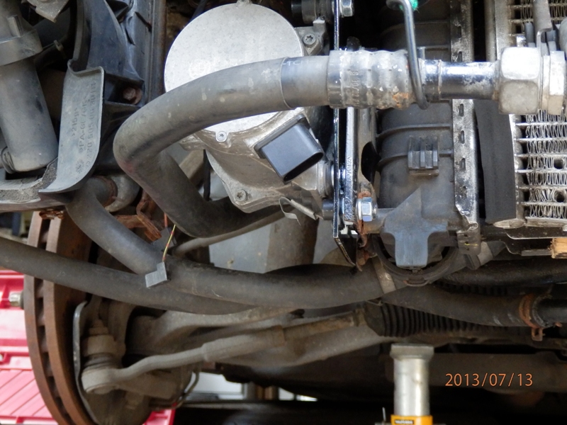
I mounted the Pierburg water pump to a metal bracket, which was in turn attached to the stock bracket. If you can remove the stock bracket (mine was corroded) do that, and bolt the new bracket directly to the radiator instead. In my case I glued some bolts to the stock bracket and to the new bracket, so that I could bolt each part to a set of studs. This makes assy much easier.
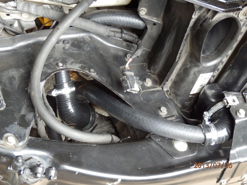
Filling and bleeding the IC system is both critical and difficult. Part of my solution (which I recommend to EVERY SINGLE PERSON with a V12TT engine) is to connect a four foot long narrow rubber tube to a T-piece at the bottom point of the system at the HE inlet. This was then run upwards past the ABC valves and left hand headlight, and alongside the AC pipes towards the suspension strut top and the soft bulkhead. This is capped and left fitted permanently, but is pulled out and topped with a funnel or small header tank to fill the system. Seen here in situ, with the headlight removed, it runs kind of diagonally, from top left to bottom right.
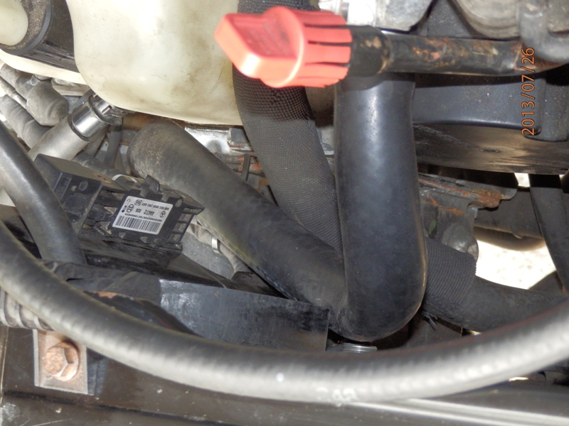
The HE and pump are connected to 3/4" pipes via 35mm to 28mm 90 degree reducing elbows (typically made from multi-layer silicone rubber). I ran a tube from the HE outlet under the Left hand head light to the inlet of the pump, at the rear. The outlet is connected with another new length of 3/4 tubing through a new route that goes behind the headlight frame and under the engine air inlet. It clears the radiator fan OK, but gets in the way when removing tha fan, so it would have been a good idea to use the stock pipe instead, even though it has a tight turn in it.
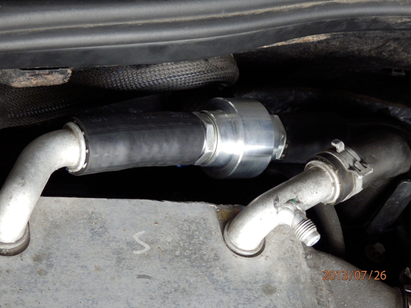
I fitted a temperature sensor hose adapter to the coolant outlet on the right hand side charge cooler. These are difficult to find - they need to fit the Tecomotive temp sensor thread AND fit 19mm pipes. Make sure you have this in your hands before you start any work (if you use the Pierburg / Tecomotive solution like me). I would rather have fitted this downstream of the Y-junction that joins the outlets of BOTH charge coolers, but the only space is in front of the engine. That means the temp sensor response would be slow, due to the length of plumbing between the IC and the sensor. This way the response time is quick.
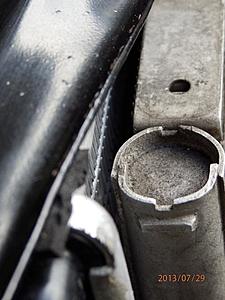
This was the real money shot for me. Can you tell what this is? I was concerned all along that I simply wouldn't be able to close the hood without the safety catch hitting the larger HE. I modified the safety catch by moving it 1/2" forwards, by drilling new holes for the mounting studs. I also had to put the catch in a vice and bend the catch itself forwards, and away from the HE. The latch works like stock, and it doesn't get too near the HE matrix. Hurrah!
This picture is upright and taken from the left hand side, with the headlights removed but with the hood closed and latched. The HE is on the right and the radiator grille is on the left. It shows the latch - the shaddowy thing in the centre, behind the Distronic radar and bracket. This clearance is fine, even if the hood is slammed down.
The only slight downside of the whole installation is that the small plastic T-handle that sticks out to release the safety catch is pushed forwards by the HE. The catch hinge touches the HE matrix, and needs some protection, and the handle itself doesn't retract all the way behind the grille - its just flush. You could shorten the handle easily enough, but it looks OK. Very happy about this.
The biggest task for me was to find the right radiator, and you wouldn't believe how many I looked at. I'm happy that the 580x499mm BMW X3 radiator is the right one - itys the biggest one I could fit, and its tight. Here are some pictures to illustrate the perfect fit.
What the heck, they have to be shrunk and uploaded sometime - lets host the pictures like before.
The suspension oil cooler (used on all BiTurbo cars) is now bolted to the HE instead of the AC condenser, and is a close fit everywhere. The mountings are essentially the same as stock, but the mountings are reduced height and the cooler is just a few mm away from the HE matrix:
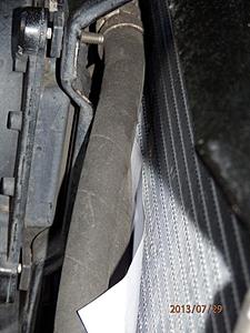
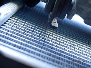
The cooler inlet/outlet pipe crimps are very close to the HE matrix - I can just get a piece of paper in between:

And the associated hoses are also very close but not touching:
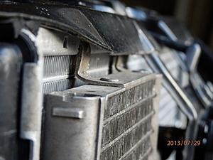
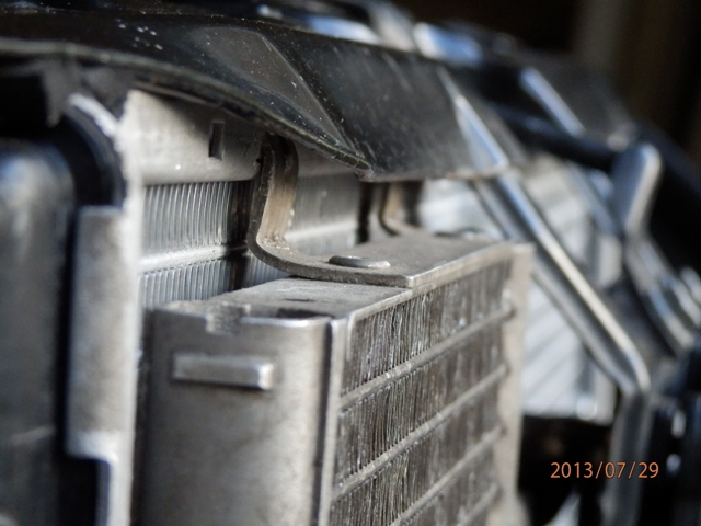
This is a sideways view of the top of the cooler and HE. I bent the top mounting brackets slightly, and slotted them into holes that I drilled and sawed into the top of the HE radiator:
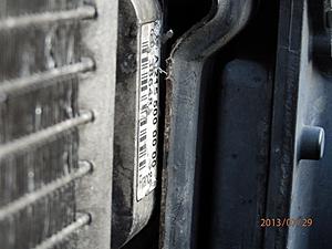
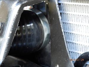
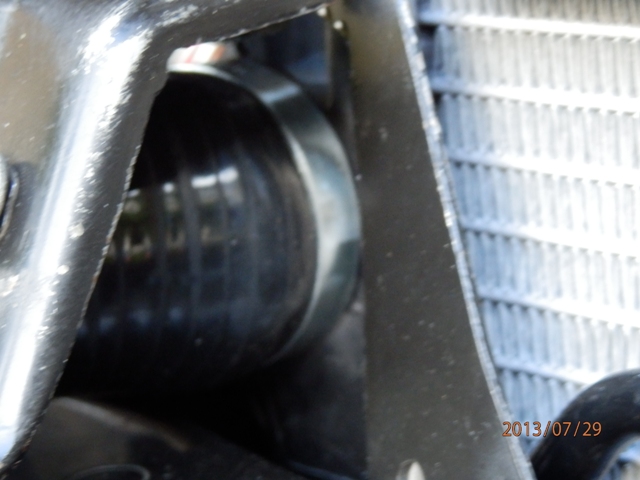
And this is the clearance between the cooler connector and the back of the Distronic radar. This is one of the reasons that I stuck to a 32mm core radiator for the new HE.
What the heck, they have to be shrunk and uploaded sometime - lets host the pictures like before.
The suspension oil cooler (used on all BiTurbo cars) is now bolted to the HE instead of the AC condenser, and is a close fit everywhere. The mountings are essentially the same as stock, but the mountings are reduced height and the cooler is just a few mm away from the HE matrix:

The cooler inlet/outlet pipe crimps are very close to the HE matrix - I can just get a piece of paper in between:
And the associated hoses are also very close but not touching:

This is a sideways view of the top of the cooler and HE. I bent the top mounting brackets slightly, and slotted them into holes that I drilled and sawed into the top of the HE radiator:
And this is the clearance between the cooler connector and the back of the Distronic radar. This is one of the reasons that I stuck to a 32mm core radiator for the new HE.
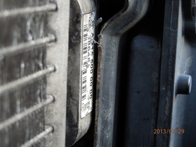
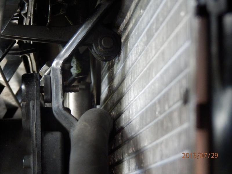
This is a poor picture of the HE outlet, with the modified headlight bracket in place. This is the downside of the BMW radiator, but the common alternative is to have the inlet or outlet right at the top, and then it fouls the radiator grille when the hood is closed.
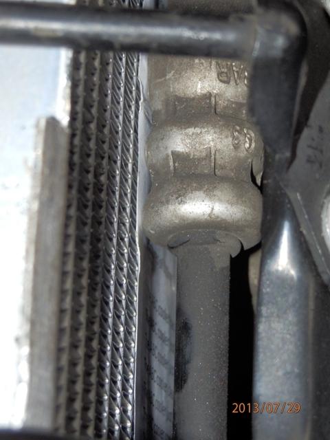
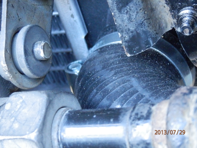
This is a general view of the bottom left-hand corner by the HE inlet and engine oil cooler. There are lots of potential fouls down there, but you can see that the oil cooler bracket clears the HE header tank.
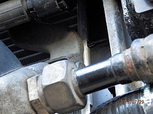
Same area, but a closer view of the right-angle reducing elbow on the HE inlet, showing how it clears the modified LHS radiator mounting bracket. That, and the RHS headlight bracket, are the major modifications.

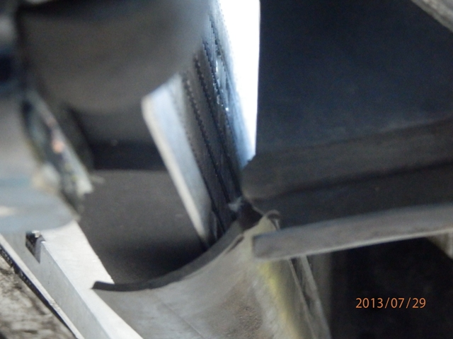
This is the bottom of the HE from underneath, showing the clearance with the engine oil cooler ducting. That rubber flange goes under the bottom of the HE, and mates up to the forward under-tray, showing how the HE runs full depth in the space available.

This is the RHS engine cooler bracket, seen from underneath, showing the clearance with the HE matrix.
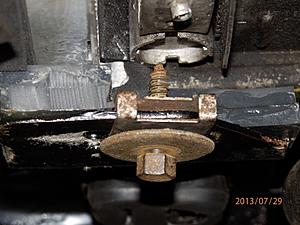
Finally, this shows that the relocated forward fixture for the forward under-tray clears all the heat exchangers. This is seen from underneath, looking sideways and upwards, with the under-tray removed but everything else in position. The bottom of the HE is top left, the AC condenser top centre, and the engine rad top right. The angled bottom of the RHS rad bracket is at the bottom - its pupose is to support the forward under-tray, but I glued and screwed some 6mm (1/4inch) rubber pads in place to support the new HE. You can just see the old fixing hole slightly to the left of the spring clip. The two mating holes on the under-tray itself obviously have to be re-drilled about 1/2 iunch further back. The under tray screws won't pierce any of the HE's no matter how hard they're screwed in.
That's pretty much how I did it. Thanks for your patience.
Nick
This is a general view of the bottom left-hand corner by the HE inlet and engine oil cooler. There are lots of potential fouls down there, but you can see that the oil cooler bracket clears the HE header tank.

Same area, but a closer view of the right-angle reducing elbow on the HE inlet, showing how it clears the modified LHS radiator mounting bracket. That, and the RHS headlight bracket, are the major modifications.
This is the bottom of the HE from underneath, showing the clearance with the engine oil cooler ducting. That rubber flange goes under the bottom of the HE, and mates up to the forward under-tray, showing how the HE runs full depth in the space available.
This is the RHS engine cooler bracket, seen from underneath, showing the clearance with the HE matrix.

Finally, this shows that the relocated forward fixture for the forward under-tray clears all the heat exchangers. This is seen from underneath, looking sideways and upwards, with the under-tray removed but everything else in position. The bottom of the HE is top left, the AC condenser top centre, and the engine rad top right. The angled bottom of the RHS rad bracket is at the bottom - its pupose is to support the forward under-tray, but I glued and screwed some 6mm (1/4inch) rubber pads in place to support the new HE. You can just see the old fixing hole slightly to the left of the spring clip. The two mating holes on the under-tray itself obviously have to be re-drilled about 1/2 iunch further back. The under tray screws won't pierce any of the HE's no matter how hard they're screwed in.

That's pretty much how I did it. Thanks for your patience.
Nick


Quote:
Hi Nick, i am monitoring all Parameters available on the CAN-Bus of the Car, besides all Conditions of the ECU, ABS etc.. there are IAT and Coolant-Temps displayed on a self-built 4,5"-Touchscreen. For Fail-Safe Reasons there are separate Instruments showing Coolant Temp/Intercooler-Temps for Backup.Originally Posted by Welwynnick
So it sounds like you needed a very good charge cooler, and the obscured position wasn't suitable. Can I ask what monitoring you were able to perform in use? Intake air temperature? Charge cooler water temp? Charge cooler flow rate? Were you unable to have a radiator in the conventiional position - or did you have one there as well?
ALL Coolers except for Steering-Fluid are replaced to the rear Position as shown on the pictures. Due to mud, debris etc. the effectiveness of the front-cooler is quickly reduced during a muddy race. During a muddy race you can observe a rise in Oil-Temps caused by mud attaching to the oil-pan alone...
BTW, we are filling our cooler-system by use of a vacuum-filling-system. this one is set on the expansion-tank. by means of pressurized air all remaining air in the cooler-system is removed through a venturi-effect. after that, the coolant is sucked into the system, filling every edge of the system.
i saw the pictures of your 'tight' installation. great work. but i saw some sharp edges and really tight fits to the cooler-core. think of expansion due to temperature and vibrations while driving the car. please check this to be shure that there will be no contact/leakage.
best regards
carsten
Thanks Carsten. When I drive my car around, I look at the 4-dial instrument cluster, wondering what what the engine is doing. Couldn't they at least have included a boost guage? Mercedes probably considered that a bit too boy-racer for a luxury car, reasoning that their buyers wouldn't be interested. But by that logic, why fit a rev-counter? Speed and load are the two key attributes of engine, and I feel like I'm driving around half-blind. I'd love IAT and I think Shardul has an after-market multi-function guage to give some of those OBD2 outputs. My pump controller has a switchable coolant temp/pump speed display, which is useful.
Regarding the installation, I was very mindful that manufacturers always use compliant mountings for radiators. I don't need to know the reason why - I just know that they do it because they need to, so I was careful to use compliant mountings and give the HE some breathing room. Some of the ABC pipes are very close, but they do move with the HE.
One of my biggest concerns was AC and engine cooling, but they seem hardly affected, even in the hottest weather. Maybe the electric radiator fan is working a bit harder than it used to in traffic, but then I never paid it a moment's attention beforehand. I'm just chuffed that I managed to get two engine radiators in there without making it look too obviously modified. With some cars the mod is obvious from outside. In hindsight, I suppose would have mounted the HE 5mm lower and 10mm to the left, but that's all I can think of. I'd like to find a way to get a W201 radiator to fit, but that's for another car....
Looking back at my first post, most modern cars with 2.0l turbo engines (either fuel) typically have 600x400x30mm intercoolers in front of the engine rads. Mine is 500mm tall, and being an HE it has the advantage of narrow water channels, so there are nearly twice as many rows and the incoming air flow through the rad is less restricted. Its a relatively cheap, light, HE as well. It could almost be considered as a sacrificial protector for the condenser and rad.
Nick
Junior Member
So...My next move is to schedule a weeks worth of vacation time...that should give me enough time to finish reading this thread!

Junior Member
Lots of info here, so What is the outside temp and what are the iats after driving around for 30min? Are the iats still close to ambient? Heat soak problem addressed and done with?
This project has taken up so much of my time this year that I've neglected many other things. I've finally replaced a few ABC hoses and a suspension strut; my wife wants me to re-tile the conservatory, my son started secondary school yesterday; I'm trying to get a very ambitious new PC working; my neighbour wants me to finish cutting down a huge hedge; I'm trying to put up a new home cinema projection screen; I've just become a scout leader; I pioneered linear power supplies for Meridian AV surround controllers and have two more units to modify, and I've picked up a burdensome new programme at work, so life's a bit busy to do EVERYTHING I want to.
I expected everyone to ask about IAT's, but just getting the new pump & radiator up and running at all has been an enormous effort and achievement, and I haven't even begun to think about quantifying the improvement. I've been so focussed on avoiding the downsides that I haven't really considered the upside. The HE is much bigger than stock; the pump is much more powerful; all the intake air HAS to go through the HE rather than round it; the pump control algorithm is programmable and much better than before; and I've developed several new methods for filling and bleeding the IC system, which I've found to be absolutely critical for the system to perform properly. That's what I'm going to talk about next.
Nick
Edit - sorry, didn't mean to be so defensive

MBWorld Fanatic!
biker349
MBWorld Fanatic!
close
Jan 14, 2023
- Join DateOct 2009
- Posts:1,924
-
iTrader Positive Feedback0
-
iTrader Feedback Score(0)
- Vehicle(s) I drivecl600
-
Likes:4,958
-
Liked:38 Times in 36 Posts
nick, i believe the saying goes 5% of the people do 95% of the work. you my friend are in that 5%.
Senior Member
I thought everyone following this thread would enjoy this test that Lingenfelter did on interccooler pump flow tests. They have a bosch pump from a cobra in the test. They even include as installed flow rates. There are some interesting results for the meziere pumps. None of the MB pumps are included but it is a good reference.
http://ls1tech.com/forums/forced-ind...g-results.html
http://ls1tech.com/forums/forced-ind...g-results.html

Former Vendor of MBWorld
shardul
Former Vendor of MBWorld
close
Jul 18, 2024
- Join DateMay 2008
- LocationHouston
- Posts:12,139
-
iTrader Positive Feedback100
-
iTrader Feedback Score(1)
- Vehicle(s) I drive2003 W211 E55, 2003 W220 S600
-
Likes:389
-
Liked:295 Times in 244 Posts
nice find
Quote:
http://ls1tech.com/forums/forced-induction/1638572-intercooler-pump-flow-testing-results.html
Thanks, that's a gold-mine of information, and very relevent to MB intercoolers. These tests are reported in various Cadallic and Camero forums, where there's generally a lot of interest in IC's. Everyone assumes the 20 gpm & 55 gpm pumps are Meziere, plus the Bosch pump part no is given as 0392-022-002, so the test results are very informative. Originally Posted by Flight Test
I thought everyone following this thread would enjoy this test that Lingenfelter did on interccooler pump flow tests. They have a bosch pump from a cobra in the test. They even include as installed flow rates. There are some interesting results for the meziere pumps. None of the MB pumps are included but it is a good reference.http://ls1tech.com/forums/forced-induction/1638572-intercooler-pump-flow-testing-results.html
Firstly, the pumps are characterised for flow and pressure, not just flow. Some manufacturers, like Bosch & Johnson do give this information, but others don't. Meziere are the glaring exception, and it seems there's a good reason. I've pointed out in this thread that I don't have any pressure/flow information for the WP136S, and the characteristics on my chart are a guess based on open-pipe flow, and electrical power consumption.
My understanding is that Meziere make ENGINE cooling pumps, and the pressure/flow characteristics are optimized for engine cooling systems, which have much lower resistance than charge coolers. The pump tests show this is borne out. Everyone thinks of the Meziere (WP136) as a 20gpm pump, but put a load on it, and it flows LESS than the Bosch (just like the Johnson CM30). I think this should answer the question once and for all, should the stock pump should be upgraded to a Johnson or Meziere? The answer is no.
Secondly, the tests also give installed performance measurements, which show how much flow resistance there is in a presumably comparable IC system. The answer is - a lot, and it suggests that the pump's static pressure (closed outlet) is the better guide to installed performance than the open pipe flow.
Thirdly, there are a few new candidate pumps for our cars. I'm not sure I want to consider the over-rated EMP pump, which looks like a monster, but the VariMax pump looks like a great candidate. The performance looks rather similar to the Pierburg CWA-50.
I'll try to combine some of the new information onto my existing chart.
Nick
The other thing I wanted to capture is a set of links to a blog by Bruce Nunnally. He’s a fanatical Cadillac STS-V owner, and the parallels between this thread and his blog are remarkable. We’re coming from the same place, but he’s rather more professional about this. He’s been performing both analytical and empirical pump evaluation, and has some interesting installed performance measurements. He’s also gone a long way to closing the loop on predicting how pump performance on the bench equates to improved car performance.
http://caddyinfo.com/wordpress/cadillac-sts-v-intercooler-pump-bucket-test/
http://caddyinfo.com/wordpress/how-cool-is-this-intercooler-pressure-versus-pump-output-and-flow-motorama/
http://caddyinfo.com/wordpress/adding-boost-pressure-to-the-lc3-4-4l-dohc-vvt-v8/
http://caddyinfo.com/wordpress/intercooler-cooling-corvette-zr-1-ls9-cadillac-cts-v-lsa-sts-v-lc3/
http://caddyinfo.com/wordpress/meziere-55-gpm-intercooler-pump/
http://caddyinfo.com/wordpress/intercooler-pump-test-4/
http://caddyinfo.com/wordpress/cadillac-sts-v-intercooler-flow-gpm-bucket-test-3/
http://caddyinfo.com/wordpress/gonna-pump-you-up-intercooler-pumps-in-series-to-maximize-cooling-motorama/
http://caddyinfo.com/wordpress/taking-cooling-cues-from-the-zl1/
http://caddyinfo.com/wordpress/datalog-analysis-of-cadillac-sts-v-ambient-vs-iat1-vs-iat2/
What’s particularly interesting are the Laminova chargecooler characteristics for the STS-V. These show the charge cooler’s heat transfer rate vs. coolant flow rate, and he can predict the benefit of upgrading the pump. This answers another question that’s been unanswered for a long time – does increasing the coolant flow necessarily improve the charge-cooling? The answer is yes, but with diminishing returns. More flow = more cooling, even up to high flow and high pressure. I’ve been saying this all year, and this is good evidence.
The other gratifying point is the typical operating conditions of the STS-V charge cooler. The nominal condition has 30 degC coolant circulating at 20 lpm and about 50kPa pressure. The intake air is 110 degC,and the air flow rate is 350 g/sec. The heat transfer rate is 17 to 22 kW, depending on coolant flow rate (corresponding to a 25-fold increase in pumping power!). Those with good memories will recall that these figures are very similar to the pure first principles analysis I did towards the beginning of this thread. I conservatively predicted that the V12TT charge cooler passed 400g/sec and needed to dissipate 20kW, rising to 30kW for a tuned engine. So I’m feeling very pleased about that.
Nick


