


Understanding Intercooling, Charge-Coolers, Heat Exchangers and Circulation Pumps
Junior Member
Joined: Feb 2013
Posts: 22
Likes: 0
From: Abu Dhabi, UAE
W221 S65 AMG, Porsche Panamera Turbo S
Hi Nick,
I've been following your posts for quite some time. Thanks for the great work you have accomplished so far.
Can you please, draft a diagram showing the new layout of the intercoolers piping as well as the new header tank. Where can I get one of those tanks. Thanks.
I've been following your posts for quite some time. Thanks for the great work you have accomplished so far.
Can you please, draft a diagram showing the new layout of the intercoolers piping as well as the new header tank. Where can I get one of those tanks. Thanks.

Thread Starter
MBWorld Fanatic!


Joined: Nov 2010
Posts: 2,605
Likes: 343
From: Welwyn, Herts, UK
2006 S600
See post 127 or thereabouts for the plumbing layout.
http://www.ebay.co.uk/itm/Alloy-0-5-...item232658abd4
I bought one of these, but hold fire until my system works properly, otherwise this MIGHT not be the right way to deal with system bleeding.
I'll be testing and comparing the CWA-100 pump soon, as well.
Nick
http://www.ebay.co.uk/itm/Alloy-0-5-...item232658abd4
I bought one of these, but hold fire until my system works properly, otherwise this MIGHT not be the right way to deal with system bleeding.
I'll be testing and comparing the CWA-100 pump soon, as well.
Nick
Last edited by Welwynnick; Jan 28, 2014 at 08:25 AM.
Thread Starter
MBWorld Fanatic!
Joined: Nov 2010
Posts: 2,605
Likes: 343
From: Welwyn, Herts, UK
2006 S600
The Money Shot
After 18 months of ownership
After 12 months of research
After 7 months of work...
Tonight I finally have my charge-cooler system working the way I always envisaged, with the following modifications:
- BMW X3 engine radiator as heat exchanger
- AMG / Pierburg CWA-100 circulation pump
- Tecomotive customised pump controller
- Header tank / swirl pot for filling and bleeding
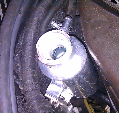
I was also worried about being able to fill and bleed the system using conventional means. To begin with, the pump seemed to froth the coolant, and I wanted to run it slowly and fill and bleed the system by itself. If you look at the pictures, you can see the tanks inlets have clear jets of coolant, with no air or vapour bubbles. Those two jets take coolant from the highest points of the system - the old "fill" ports on top of the IC's, which I had drilled out and fitted with bleed nipples. Those bleed outlets have drilled holes only a millimetre or two in diameter, so are less than one percent of the main pipe's cross-sectinal area. Yet you can still see good, strong jets into the swirl pot (which swirls quickly enough to generate a deep conical votex). Those pictures were taken with the pump running at mid-speed setting, so the unrestricted flow in the 3/4" pipes must be strong.
I'd particularly like to thank Tobias Mucke from Tecomotive for modifying the controller for IC duty, and for providing superb support all along.
I think I'm done now.
Nick


Last edited by Welwynnick; Feb 8, 2014 at 06:36 AM.
Junior Member
Joined: Feb 2013
Posts: 22
Likes: 0
From: Abu Dhabi, UAE
W221 S65 AMG, Porsche Panamera Turbo S
Thanks Nick for your elaborate details. Is it possible to list the additional plumbing parts needed such as bleed valves, piping, elbows, etc. Your work has inspired many of your followers, I believe we all need to get it right down to bolts and nuts
Thread Starter
MBWorld Fanatic!
Joined: Nov 2010
Posts: 2,605
Likes: 343
From: Welwyn, Herts, UK
2006 S600
I haven't compiled a parts list (important though it is), but I did draft a top-level procedure. Of course, this relates to the complete mods that I have done, and other people won't want to do all of them.
For example, on an S65 it would be difficult to replace the HE, as its sandwiched between the condenser and the rad, and it carries the PAS cooler.
On the W216/221, the radiator is a different size to the W215/220, so the BMW X3 rad might not fit.
People can pick and chose which mods to incorporate, and work out the parts required. They're mostly independent mods, though if you want to use the Tecomotive pump controller, then you obviously have to use a Pierburg pump.
For many things, its more down to materials rather than parts. For example, you'll need lots of 8mm and 19mm hose, jubilee clips, tie-wraps, automotive wiring and MB 325.0 antifreeze.
There are two main things to concentrate on:
1. How to connect inlets and outlets of the radiator and the pump?
2. How to plumb the temp sensor for the pump controller into the IC circuit
I'll try to put a more definitive parts list together, as one of the worst things is starting the job and realising that it takes a fortnight to get an essential part. Here's the old procedure, though:
Nick
For example, on an S65 it would be difficult to replace the HE, as its sandwiched between the condenser and the rad, and it carries the PAS cooler.
On the W216/221, the radiator is a different size to the W215/220, so the BMW X3 rad might not fit.
People can pick and chose which mods to incorporate, and work out the parts required. They're mostly independent mods, though if you want to use the Tecomotive pump controller, then you obviously have to use a Pierburg pump.
For many things, its more down to materials rather than parts. For example, you'll need lots of 8mm and 19mm hose, jubilee clips, tie-wraps, automotive wiring and MB 325.0 antifreeze.
There are two main things to concentrate on:
1. How to connect inlets and outlets of the radiator and the pump?
2. How to plumb the temp sensor for the pump controller into the IC circuit
I'll try to put a more definitive parts list together, as one of the worst things is starting the job and realising that it takes a fortnight to get an essential part. Here's the old procedure, though:
Buy a new BMW X3 radiator and cut off all the brackets and ribs.
Shorten the inlet & outlet to leave a single swage, and trim swage back to 1mm high.
Cut back the HE top stiffener to clear the safety catch.
Cut slots into the HE top stiffener to mount the ABC cooler (like AC condenser).
Flatten the ABC cooler bracket and bolt through the HE.
Bolt the ABC cooler outlet pipe bracket through the HE.
Cut and bend the top rail to clear the HE header tanks and ABC cooler
Lower the ABC cooler outlet pipe bracket by �” and route through the headlight bracket.
Move the safety catch �” forwards so the tang clears the HE.
Move the ABC thermostat, pipes and brackets �” to the left (tricky but critical).
Bend or shim the engine oil cooler �” forwards to clear the HE.
Move the forward fasteners on the forward under-tray back �”.
Move the RHS horn up �” to clear the larger pump.
Cut away the LHS radiator bracket to clear the HE inlet.
I cut the RHS radiator bracket back, but this probably isn’t necessary.
Cut away the RHS headlight bracket to clear the HE outlet (though not this much).
The Pierburg CWA 200 pump faces backwards so the outlet faces upwards.
Cut and drill a new pump mounting plate to go directly on the rad.
The CWA 200 pump needs its own, larger mounting plate.
The CWA 50 & 100 pumps can probably use the stock mount& orientation.
Raise the Pierburg pump so the electrical connector clears the radiator bracket.
Connect the pump and HE to the stock plumbing using appropriate reducing elbows.
Trim the radiator intake ducting to clear the additional and relocated plumbing.
Fit IC thermostat to RHS IC outlet pipe.
Wire pump controller to battery, pump, ignition and temp sensor.
Last edited by Welwynnick; Feb 8, 2014 at 06:36 AM.
Thread Starter
MBWorld Fanatic!
Joined: Nov 2010
Posts: 2,605
Likes: 343
From: Welwyn, Herts, UK
2006 S600
1st Feb 2014: seven months and many hours and pounds after starting work, I finally got to drive Mercury Mercedes with the IC system working how I wanted it. I didn't have an OBD2 reader hooked up, so I couldn't see IAT's today, but I could see the IC coolant temp from the Tecomotive controller.
The initial impression was that the motor was always "on", and I wasn't taking a chance or patiently waiting for the pump to switch on. The car felt eager and responsive, rather than slightly languid and reluctant to get going, like it had to be poked with a stick.
In normal running, the controller's crude temp display showed 2 LEDs out of 7. The LED's correspond to the target temp range that can be set - 0 to 55 degC. I had the controller set to position 8, which was 20 degC. On WOT the temp generally went up to LED3 - say 20 to 25 degC. On one instance - as hard as I ever drive - standstill to a high speed up a long hill - it showed LED4 for a few seconds. I think that's about 28 to 31 degC, and that's with a target temp of 20 degC. It went back down in a few seconds.
There's lots of tunes to play, and the next thing I'll do is set a lower target temp, and then change the display to show pump speed. When I got home I left the engine running and felt the charge coolers, which were again cool to the touch, even after hard driving. The IC header tank was swirling nice and slow, with no sign of bubbles in the coolant, which I was very pleased about.
Because this endeavour has been so difficult, I've had doubts all along whether I've taken the right approach. There are many short-cuts which might have achieved the same objective - different pump, different HE, skip the Tecomotive controller, etc. But I'm happy now that I've done the right thing. I think many people might prefer a custom-made HE to make the installation easier, and I wouldn't argue with that. If I did it again I'd be tempted to use an E-class radiator instead of the X3 rad, and use that to cool the ABC oil instead of the silly stock cooler. But in hindsight I don't think I've taken the wrong path - I think this is how all V12TT's should be.
One other thing. Before I put the under-tray back on, I measured the current consumption of Pierburg pump. When the AMG pump was full-on, it measured 4.9 to 5A in my system, and I got 4.9A from the Transit pump, so I take it that my batch of coolant pumps are indeed CWA-100's, rather than CWA-50's. Only difference is teh Transit pump actualy responds to the Tecomotive controller. That's good news! Anybody else want one?
Very happy now
Nick
Last edited by Welwynnick; Feb 1, 2014 at 01:10 PM.
Thread Starter
MBWorld Fanatic!
Joined: Nov 2010
Posts: 2,605
Likes: 343
From: Welwyn, Herts, UK
2006 S600
MB World Stories
The Best of Mercedes & AMG

Manual Mercedes? 6 Times Sindelfingen Let Drivers Have All The Fun
Verdad Gallardo
Mercedes SLR McLaren 722 S Is Extremely Rare Example Modified by McLaren
Verdad Gallardo
8 Classic Boxy Mercedes Designs That Have Aged Like Fine Wine
Verdad Gallardo
Flawlessly Restored Mercedes 190E Evo II Heads to Auction
Verdad Gallardo
Electric Mercedes C-Class Unveiled: 11 Things You Need to Know
Verdad Gallardo
Mercedes EQS Gets A Major Update: Everything You Need to Know
Verdad Gallardo
5 Underrated Mercedes-Benz Models That Don't Get the Love They Deserve
Verdad Gallardo
Mercedes 300D Has Pushed Well Past 1 Million Miles and It Ain't Stopping
Verdad Gallardo
10 Most Reliable Mercedes-Benz Models You Can Buy Used
Verdad Gallardo
Thread Starter
MBWorld Fanatic!
Joined: Nov 2010
Posts: 2,605
Likes: 343
From: Welwyn, Herts, UK
2006 S600
I've been trying to find that out for months - how do you know? Do you work for Pierburg?
I believe the BMW pump is a CWA-50, and has the same conenctor as the AMG pump.
The CWA-200 is quite different, and has a different connector (which I completely forgot about until I brought the AMG pump home).
The Tecomotive kit comes with a CWA-200 connector, so I had to get the BMW connector, which fits both the AMG and Transit pumps.
Any ideas why the AMG pump won't talk to the Tecomotive controller?
Cheers, Nick
Newbie
Joined: Feb 2014
Posts: 6
Likes: 0
c220
Hi Nick,
I have been trying to source the connector for these Transit pumps, so I have been talking to a guy at piersburg.
I will ask him about the CWA-100.
One other question, are there any numbers on the BMW connector? I'm sure they are not produced by BMW.
Paulo
I have been trying to source the connector for these Transit pumps, so I have been talking to a guy at piersburg.
I will ask him about the CWA-100.
One other question, are there any numbers on the BMW connector? I'm sure they are not produced by BMW.
Paulo
Last edited by Paulinho19; Feb 8, 2014 at 09:48 AM.
Thread Starter
MBWorld Fanatic!
Joined: Nov 2010
Posts: 2,605
Likes: 343
From: Welwyn, Herts, UK
2006 S600
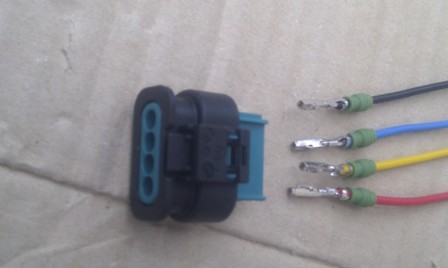
These are the parts I ordered from my BMW dealer:
1 x 12527549033 Plastic Socket Housing
4 x 61138366245 Rubber sealing grommets
4 x 12527545858 Individual Socket Pins
Here are the parts that I bought (two sets - one for the car, one for the pump test rig)
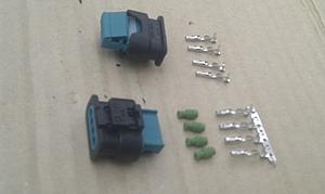
You can probaby crimp the cables to the pins, but I soldered them instead:
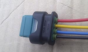
And here's the assembled connector:
1 x 12527549033 Plastic Socket Housing
4 x 61138366245 Rubber sealing grommets
4 x 12527545858 Individual Socket Pins
Here are the parts that I bought (two sets - one for the car, one for the pump test rig)

You can probaby crimp the cables to the pins, but I soldered them instead:
And here's the assembled connector:

Thread Starter
MBWorld Fanatic!
Joined: Nov 2010
Posts: 2,605
Likes: 343
From: Welwyn, Herts, UK
2006 S600
These are the markings on the connector:
PA66 GF25
872-859
7 549 033-01
1 2 3 4
The first thing I did when I got the connectors was search for markings and part numbers that would let me find another supplier, but I found nothing. The only meaning I could get from them was the plastic material. I suppose I was put off going to a BMW dealer to buy a connector, but don't be. They only cost a few pounds and took two days to get in. I believe Audi and Mercedes use this pump on their most recent and most expensive turbo cars, so maybe you could get the connectors from them, but you definitely can get them from BMW.
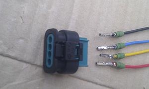
These are the connections that I made, and which do work with the Transit pumps:
Pin 1: Ground : Red
Pin 2: Ground : Yellow
Pin 3: Control : Blue
Pin 4: Battery : Black
For some reason the pin-out is reversed with the CWA-200 pump.
Nick
PA66 GF25
872-859
7 549 033-01
1 2 3 4
The first thing I did when I got the connectors was search for markings and part numbers that would let me find another supplier, but I found nothing. The only meaning I could get from them was the plastic material. I suppose I was put off going to a BMW dealer to buy a connector, but don't be. They only cost a few pounds and took two days to get in. I believe Audi and Mercedes use this pump on their most recent and most expensive turbo cars, so maybe you could get the connectors from them, but you definitely can get them from BMW.
These are the connections that I made, and which do work with the Transit pumps:
Pin 1: Ground : Red
Pin 2: Ground : Yellow
Pin 3: Control : Blue
Pin 4: Battery : Black
For some reason the pin-out is reversed with the CWA-200 pump.
Nick
Last edited by Welwynnick; Feb 9, 2014 at 05:09 AM.
Thread Starter
MBWorld Fanatic!
Joined: Nov 2010
Posts: 2,605
Likes: 343
From: Welwyn, Herts, UK
2006 S600
I hate to throw yet another option in the pot, but I was answering someone's question on a Jabsco pump, and came across another model. I thought I'd already seen and disregarded it for some reasons, but maybe I looked at the wrong version. Jabsco make a wide range of industrial and marine pumps, and I've previously mentioned that the obvious one for IC pumping is not the popular 100lpm 50840, but it's high-pressure big brother, the 80lpm 50860.
50840-2012
23920-2213
http://www.google.co.uk/url?sa=t&rct...60983673,d.d2k
http://www.jabscoshop.com/files/UTIL...C%20doc553.pdf
50840-2012
- � 232.27 ex. VAT
- Connections: - �”BSP internal threaded ports
- Dimensions: - 163mm long, 120mm wide, 122mm high
- Fuse Size: - 10 amp
- Maximum Current: - 7 amp
- Output: - 100 litres/minute (22 gallons/minute) @ 0.1m head
- High output, continuous rated centrifugal pump
- Robust stainless steel body
- Can be used with shut-off nozzle
- Non-self-priming, requires flooded suction
- Maximum recommended total head 4m
- Packaged Dimensions: L:24.00 x H:13.00 x W:18.00cm
- Actual Weight: 2.98 Kg (Approx. 3.48 Kg packed)
- � 253.38 ex. VAT
- Connections: - �”BSP internal threaded ports
- Dimensions: - 205mm long, 120mm wide, 122mm high
- Fuse Size: - 25 amp
- Maximum Current: - 21 amp
- Output: - 80 litres/minute (18 gallons/minute) @ 0.1m head
- High output, intermittent rated centrifugal pump
- Robust stainless steel body
- Can be used with shut-off nozzle
- Non-self-priming, requires flooded suction
- Maximum recommended total head 12m
- Minimum recommended total head 5m
- Packaged Dimensions: L:31.00 x H:14.00 x W:16.00cm
- Actual Weight: 4.90 Kg (Approx. 5.40 Kg packed)
23920-2213
- � 320.00 ex. VAT
- ‘Utility Puppy 3000’ self-priming pump 12 volt d.c.
- Connections: - �” BSP inlet and discharge ports.
- Dimensions: - length 220mm, width 125mm, height 105mm
- Fuse Size: - 25 amp
- Maximum Current: - 21 amp
- Output: - up to 50 litres/minute (11 gallons/minute).
- Max 12m head
- Built-in dry-running protection for up to 10 minutes after initial prime
- Rapid self-priming from dry up to 2.4m
- Carbon-ceramic shaft seal
- Non-rusting bronze body
- Continuously rated electric motor
- Simple, fully serviceable design with few wearing parts
- Packaged Dimensions: L:29.00 x H:14.00 x W:16.00cm
- Actual Weight: 4.65 Kg (Approx. 5.15 Kg packed)
http://www.google.co.uk/url?sa=t&rct...60983673,d.d2k
http://www.jabscoshop.com/files/UTIL...C%20doc553.pdf
Last edited by Welwynnick; Feb 9, 2014 at 07:48 AM.
Thread Starter
MBWorld Fanatic!
Joined: Nov 2010
Posts: 2,605
Likes: 343
From: Welwyn, Herts, UK
2006 S600
Just a quick observation from driving around this week.
I expected the Tecomotive controller would let me test and monitor the IC system, but I wasn't expecting many surprises in the performance department. With the target temperature set at 15 or 20degC, the actual IC coolant temp moved little. Under full throttle I guess the coolant temp went up 10degC at most, then came down very quickly afterwards.
However, the highest coolant temps that I saw were under quite different circumstances. After driving a few miles - sufficient to get the engine fully warmed-up, I sometimes parked for an hour, and went out again later. In those cases the engine compartment would heat-soak the IC system, which then reached 40degC (and the IC & HE were physically warm to the touch).
For a mile or so, the IC pump would come, but with the engine temp at 70 or 80degC, the engine fan ran slowly, and there wasn't much airflow while driving slowly to begin with, so the IC temp took a few minutes to go down. Speed-up again - and normal operation and temperatures were resumed.
It has only been that particular circumstance where I've seen higher IC temps - no amount of fast driving would ever get it so high. That suggests that the stock IC system will also see similar behaviour - without being able to see what's going so clearly. Of course it will also cool things down, but with the thermostatic control set to higher temps than I used on the Tecomotive, it might not necessarily bring temps down so quickly.
So just an interesting and unexpected observation.
Nick

Member
Joined: Dec 2010
Posts: 84
Likes: 1
From: Wollongong, sydney Australia
R170 99SLK230 + SLK32
These are the markings on the connector:
PA66 GF25
872-859
7 549 033-01
1 2 3 4
The first thing I did when I got the connectors was search for markings and part numbers that would let me find another supplier, but I found nothing. The only meaning I could get from them was the plastic material. I suppose I was put off going to a BMW dealer to buy a connector, but don't be. They only cost a few pounds and took two days to get in. I believe Audi and Mercedes use this pump on their most recent and most expensive turbo cars, so maybe you could get the connectors from them, but you definitely can get them from BMW.
These are the connections that I made, and which do work with the Transit pumps:
Pin 1: Ground : Red
Pin 2: Ground : Yellow
Pin 3: Control : Blue
Pin 4: Battery : Black
For some reason the pin-out is reversed with the CWA-200 pump.
Nick
7.01360.48.0
anyways - I tried to decipher the plug connector for it - I'll need one of these....
Is this photo for the CW50 or CW100-200?
I'm also interested in setting up the comms from my Arduino rig, but it may be easier just to vary the voltage to the motor through +/- than start trying to play with comms...
End use - SLK32 Intercooler setup.
If someone can send a link to an operating manual for the pump - much appreciated
Any thoughts?
Last edited by Billy22Bob; Mar 17, 2014 at 09:03 PM.

Newbie
Joined: Mar 2014
Posts: 5
Likes: 0
Almost anything with 4 wheels
Heat soak and low speed temps
That other controller you referenced from SFR Electronics has a relay output for a fan. Does the controller you are using have that option? If so maybe a fan on the intercooler radiator that is controlled/based on IC temperature would help when stopped or at low speeds (especially after a heat soak event). If it had a timer on it you could even let it run on after the engine shut down (but not for long or the battery would be dead).
Just a quick observation from driving around this week.
I expected the Tecomotive controller would let me test and monitor the IC system, but I wasn't expecting many surprises in the performance department. With the target temperature set at 15 or 20degC, the actual IC coolant temp moved little. Under full throttle I guess the coolant temp went up 10degC at most, then came down very quickly afterwards.
However, the highest coolant temps that I saw were under quite different circumstances. After driving a few miles - sufficient to get the engine fully warmed-up, I sometimes parked for an hour, and went out again later. In those cases the engine compartment would heat-soak the IC system, which then reached 40degC (and the IC & HE were physically warm to the touch).
For a mile or so, the IC pump would come, but with the engine temp at 70 or 80degC, the engine fan ran slowly, and there wasn't much airflow while driving slowly to begin with, so the IC temp took a few minutes to go down. Speed-up again - and normal operation and temperatures were resumed.
It has only been that particular circumstance where I've seen higher IC temps - no amount of fast driving would ever get it so high. That suggests that the stock IC system will also see similar behaviour - without being able to see what's going so clearly. Of course it will also cool things down, but with the thermostatic control set to higher temps than I used on the Tecomotive, it might not necessarily bring temps down so quickly.
So just an interesting and unexpected observation.
Nick
I expected the Tecomotive controller would let me test and monitor the IC system, but I wasn't expecting many surprises in the performance department. With the target temperature set at 15 or 20degC, the actual IC coolant temp moved little. Under full throttle I guess the coolant temp went up 10degC at most, then came down very quickly afterwards.
However, the highest coolant temps that I saw were under quite different circumstances. After driving a few miles - sufficient to get the engine fully warmed-up, I sometimes parked for an hour, and went out again later. In those cases the engine compartment would heat-soak the IC system, which then reached 40degC (and the IC & HE were physically warm to the touch).
For a mile or so, the IC pump would come, but with the engine temp at 70 or 80degC, the engine fan ran slowly, and there wasn't much airflow while driving slowly to begin with, so the IC temp took a few minutes to go down. Speed-up again - and normal operation and temperatures were resumed.
It has only been that particular circumstance where I've seen higher IC temps - no amount of fast driving would ever get it so high. That suggests that the stock IC system will also see similar behaviour - without being able to see what's going so clearly. Of course it will also cool things down, but with the thermostatic control set to higher temps than I used on the Tecomotive, it might not necessarily bring temps down so quickly.
So just an interesting and unexpected observation.
Nick
Thread Starter
MBWorld Fanatic!
Joined: Nov 2010
Posts: 2,605
Likes: 343
From: Welwyn, Herts, UK
2006 S600
That other controller you referenced from SFR Electronics has a relay output for a fan. Does the controller you are using have that option? If so maybe a fan on the intercooler radiator that is controlled/based on IC temperature would help when stopped or at low speeds (especially after a heat soak event). If it had a timer on it you could even let it run on after the engine shut down (but not for long or the battery would be dead).
One snag, though. The X3 radiator was chosen to fill every millimetre of space available, and it does. There's no space anywhere for another fan, either in front of, or behind, the radiator pack.
I don't think its a big problem though. When you stop for a while, the engine cools down and the IC warms up. When you start off again, you wait a mile for the high temp system to warm up and the low temp system to cool down again. I wouldn't floor it with an engine that hadn't warmed up.
Nick
Newbie
Joined: Mar 2014
Posts: 5
Likes: 0
Almost anything with 4 wheels
Post shut down circulation
Could you configure it to to keep circulating the pump for a while after shut down. That would help reduce the heat soak - better for long term durability of everything and you start at a lower temperature when you get back in the vehicle agaon so you have better power on initial re-start.
Yes, the Tecomotive controller also has a fan controller, though I don't use it. The main engine fan won't run when the engine doesn't, but the tecomotive can be configured to run anytime.
One snag, though. The X3 radiator was chosen to fill every millimetre of space available, and it does. There's no space anywhere for another fan, either in front of, or behind, the radiator pack.
I don't think its a big problem though. When you stop for a while, the engine cools down and the IC warms up. When you start off again, you wait a mile for the high temp system to warm up and the low temp system to cool down again. I wouldn't floor it with an engine that hadn't warmed up.
Nick
Thread Starter
MBWorld Fanatic!
Joined: Nov 2010
Posts: 2,605
Likes: 343
From: Welwyn, Herts, UK
2006 S600
http://www.lingenfelter.com/LPEforum...pump-test-data
Last edited by Welwynnick; Mar 23, 2014 at 05:02 AM.


