When you click on links to various merchants on this site and make a purchase, this can result in this site earning a commission. Affiliate programs and affiliations include, but are not limited to, the eBay Partner Network.
Maybe I don't know where to look, but I have not found a thread combining the W221 CAN bus knowledge, so here it is - if anyone has any information please contribute!
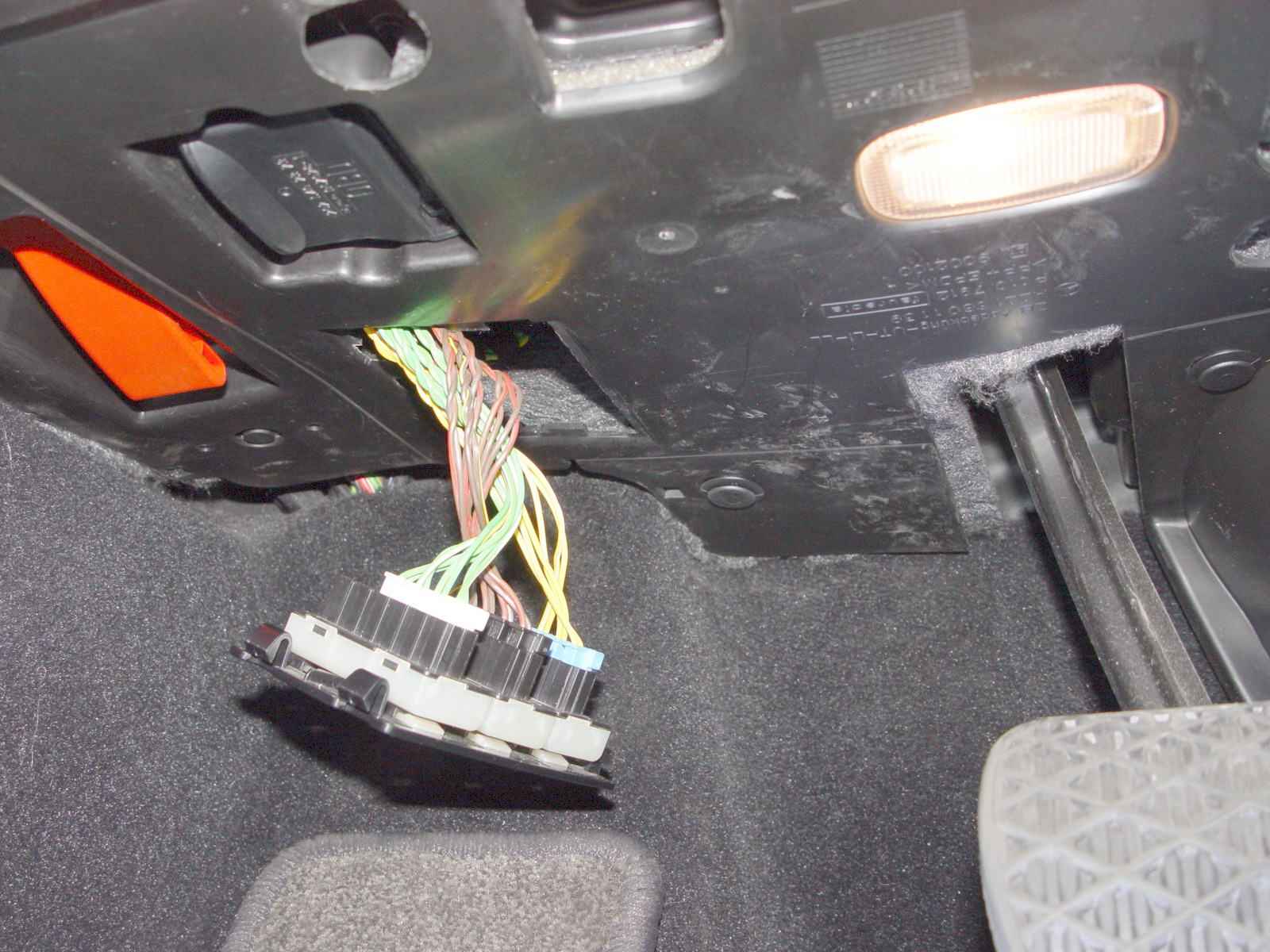
For starters, here is the access location under the dash, with 3 groups of wires: green, brown and yellow. Now the questions would be: which CAN bus serves which systems in the car, which signals are on which wires, what are corresponding messages on the CAN buses etc. Thanks!
this is quite a nice one on why the SDVC is too complex amd merc documentation meaningless as they make up lies (and or leave stiff out of the owners manual)
Speed-dependent volume control (SDV) and Dynamic Range
The volume is adapted to the noise level in the passenger compartment by GAL and the automatic vehicle interior noise adaptation feature DRO. In the process the vehicle speed signal and signal input to the sound amplifier microphone (B25/6) are used as a relationship indicator.
�. The signals to get from the mic go via the upper control panel round a Lin bus, round the rear Sam and back to the Amp. And the docs wrong, the bold red bit doesn't exist
Volume control of Nav or TMC
A certain difference in volume (adjustable in the Volume setting "System settings" menu) between the audio signal and the voice output is maintained automatically. This means that voice output remains audible even in the case of loud audio output.
And the Mute between source playing and any traffic messages or Nav instructions gets broken when they SCN incompatible facelift software (after telling you in Xentry its needed)
Can any one here without broken rear SAM software confirm this? (you can see these settings change in diagnostic but nothing changes on the audio and it doesn't remember the setting chosen - mine always reverts to middle with two either side)
When a Nav voice instruction is playing, if you press down and hold the COU (comand knob) at this point you have 5 positions two left, the middle (mine defaults to) and two to the right. Which I guess are 0%, 25%, 50%, 75% and 100% fade of other sources. I can't test this on mine as Mercedes vandalised my car, but would be interesting to hear if it works on unmolested vehicles ?
On a W211 this level of muting between sources and overlaid messages Phone / TMC / Nav instructions, is user configurable on the comand screen..... the paragraph above is the UNDOCUMNENTED way I think the 221 is supposed to do it...
Count me in. I've worked with microcontrollers for years (lots of years) and have worked with a number of communication buses, but have never had occasion to use the CAN bus. Given the potential for automating some simple tasks that I'd like automated in the W221, I've put that on my to-do list. There are a couple of things I'd love to be able to do, like automatically disable Park Assist when the car is started (just as an example). I suspect it would be trivially simple to do once one determines the proper incantation -- err, I mean message to stuff onto the bus.
In case I'm not being sufficiently clear, here's what I mean. Right now I start the car, and if I remember to, press the PA button to turn it off. If I don't remember to do that, I'm usually reminded to do it during the first few traffic stops when it alarms and *****es at me because of some other vehicle's radars. What I have in mind is a trivially simple device that I can connect to the car's CAN bus that will, when the car is started, send a message disabling PA. This could be as simple as the message from the control unit servicing the dash buttons (I suspect it's N72.1 UCP, but I'll have to check) saying that the PA button was pressed.
There are a few other odds & ends I have in mind, but that's really the first, and a great excuse to play around with the CAN bus just to get my feet wet. I'm somewhat encouraged by the amount of information that is out there. Very little of it is for the W221, but I would guess that much of it may be the same between series. I'm sure M-B didn't start from a completely clean sheet with each model.
I'll be spending some "quality time" with the car and the laptop next weekend, not digging into the CAN bus quite yet but looking into figuring out some of the basics. Anything I find, I'll share.
The other thing I’d like to do, is to have his and hers key functionality. Meaning when I open the car with my key the seats and steering wheel move into my position and vice versa. Apparently MB disabled that feature as owners got confused...
i did a few “funky” things with CAN bus on my Porsche with an Arduino and would love to do similar things on my W221
Last edited by Hatzenbach; Oct 4, 2020 at 01:01 PM.
Sounds like we are aligned! I have similar background and plans as DaleB (plus I worked with CAN bus years ago). @Plutoe - what is the top-down path to find scanbus in Xentry, so people who have it know where to find it?
I assume Mercedes documentation may be incomplete or incorrect or not released to the public at all, so most of the work will be done using a protocol analyzer capturing the message traffic and transferring results to a new control box or boxes.
There are plenty of things we can change and "break". Default starting sequence for Park Assist disabled would be a place where I would start as well. In addition to other ideas mentioned above I would disable the multi zone climate control "feature" which automatically overwrites all settings and sets the rest of the car to MAX or MIN when one zone is set to MAX or MIN. To me it defeats the purpose of multi zone climate control - occupants should be able to individually choose if they want MIN or MAX or something in between, just like in other Mercedes models I've used.
I don't think there are 11 buses, I think there are 3 in this photo (as in 3 colors), they may be going to 11 destinations from the box pictured.
Last edited by George993; Oct 4, 2020 at 09:12 PM.
Finally I have also found the StarFinder for W221 on the web at: http://benz.ehost.tj/221/webetm/webe...rt_finder.html see for example where N62 is located (an exercise for those not yet familiar with StarFinder).
(Presumably the same info can be obtained from XENTRY, but not everyone has it, and those who have it don't always have all the options and extensions)
So we have found the list of all the CANs, the components connected to each and how they are interconnected. Here is a sample overall picture of those components:
Last edited by George993; Oct 4, 2020 at 09:24 PM.
Overall network
Basically, the following data bus systems are involved in the networking:
Telematics CAN
Interior CAN
Drive train CAN
Diagnostic CAN
Chassis CAN
Central CAN
Front end CAN
Vehicle dynamics CAN
Media Oriented System Transport (MOST)
Distinguishing features
The telematics CAN is responsible for telecommunication data transfer. It networks the COMAND controller unit with the control units for the rear functions. The telematics CAN operates at a transfer rate of 125 kBit/s.
The interior CAN is responsible for data transfer in the vehicle interior. It interconnects the different systems that can be operated by the driver or the front passenger (e.g. power windows, interior air conditioning system etc.). The interior CAN operates at a transfer rate of 125 kBit/s.
The drive train CAN is responsible for data transfer for the drive systems. The drive train CAN operates at a transfer rate of 500 kBit/s.
The diagnostic CAN is responsible for transferring the diagnostic data to STAR DIAGNOSIS and for connecting the emergency call system control unit. The diagnostics CAN operates at a transfer rate of 500 kBit/s.
The chassis CAN is responsible for data transfer between the chassis systems. The chassis CAN operates at a transfer rate of 500 kBit/s.
The central CAN is primarily responsible for data transfer between the COMAND controller unit (telematics CAN, MOST) and the central gateway control unit. The central CAN operates at a transfer rate of 500 kBit/s.
The front end CAN is responsible for data transfer between the Xenon headlamp control units, electric parking brake control unit to the central gateway control unit. The front end CAN operates at a transfer rate of 500 kBit/s.
The vehicle dynamics CAN is responsible for data transfer from driving safety systems (e.g. Distronic, Night View Assist, rotational speed etc.). The vehicle dynamics CAN operates at a transfer rate of 500 kBit/s.
The telematics CAN interconnects the following control units:
COMAND controller unit
Left rear display
Right rear display
COMAND display
Front central operating unit
TV combination tuner
Rear AC control unit
Audio/video controller control unit
RCP [HBF] control unit
The following control units are connected to each other over the interior CAN:
STH control unit
Lumbar pump
Multicontour seat pneumatic pump
Pneumatic pump for dynamic seat control
WSS (Weight Sensing System) control unit
Front SAM control unit with fuse and relay module
Rear SAM control unit with fuse and relay module
AAC [KLA] control unit
Rear control unit (N22/6) (model 216)
Rear seats control unit
Special vehicle multifunction control module (SVMCM)
Trailer recognition control unit
Left front seat control unit
Right front seat control unit
Left front multicontour backrest control unit
Right front multicontour backrest control unit
Left front dynamic seat control unit
Right front dynamic seat control unit
Left rear multicontour backrest control unit
Right rear multicontour backrest control unit
PTS control unit
Backup camera control unit
Door control module left
Door control module front left
Door control module right
Door control module front right
Door control module rear left
Door control module rear right
Keyless Go control unit
Overhead control panel control unit
Upper control panel control unit
EIS [EZS] control unit
TPM [RDK] control unit
Central gateway control unit
Weight Sensing System (WSS) control unit (N110) (model 216)
WSS (Weight Sensing System) control unit
TLC [HDS] control unit
The following control units are connected to each other over the drive train CAN:
Intelligent servo module for DIRECT SELECT
CDI control unit
ME-SFI [ME] control unit
ETC [EGS] control unit
Fuel pump control unit
Fully integrated transmission control (VGS) control unit
The following control units are connected to each other over the diagnostics CAN:
Central gateway control unit
Emergency call system control unit
The following control units are connected to each other over the chassis CAN:
Left front reversible emergency tensioning retractor
Right front reversible emergency tensioning retractor
Restraint systems control unit
CDI control unit
ME-SFI [ME] control unit
ESP control unit
AIRmatic with ADS control unit
ABC control unit
Radar sensors control unit (SGR)
EIS [EZS] control unit
Steering column module
Vehicle power supply control module
Central gateway control unit
The following control units are connected to each other over the central CAN:
Instrument cluster
COMAND controller unit
Central gateway control unit
The following control units are connected to each other over the front end CAN:
Electric parking brake controller unit
Xenon headlamp control units
Central gateway control unit
The following control units are connected to each other over the vehicle dynamics CAN:
DTR controller unit
Yaw rate, lateral and longitudinal acceleration sensor
ESP control unit
Radar seniors control unit (SGR)
Night vision assist control unit
The MOST interconnects the following control units:
COMAND controller unit
TV combination tuner
Voice control system (VCS [SBS]) control unit
SDAR control unit
Audio tuner control unit
UPCI control unit Data transfer between the bus systems
The following control units form the interface between the bus systems:
The central gateway control unit connects the interior CAN, diagnostic CAN, chassis CAN, central CAN and the front end CAN
The COMAND controller unit connects the telematics CAN, central CAN and the MOST
The TV combination tuner connects the telematics CAN with the MOST
The ESP control unit and the Radar sensors control unit connect the chassis CAN with the vehicle dynamics CAN
The CDI control unit or the ME-SFI [ME] control unit connects the drive train CAN with the chassis CAN
I would disable the multi zone climate control "feature" which automatically overwrites all settings and sets the rest of the car to MAX or MIN when one zone is set to MAX or MIN. To me it defeats the purpose of multi zone climate control - occupants should be able to individually choose if they want MIN or MAX or something in between,
Yep I think you get three, two two wire and the one wire lin bus ?
as for the bit of your post I left above, this is designed as a convenience feature. The ac and heating should be so powerful (and are when its all working correctly), that only a strange person would ever expect to use the extremes. In fact the next notch, from either extreme will give full heat or cooling capacity for each location. The next notch that brings in max / min setting for all, is for when the cars at melting point inside and the idea is to try and get the whole car cool asap or indeed vice versa re heating. Unlike my BM where they got it wrong. On my S class as soon as you take off the full extreme everyone goes back to their personalised settings. Its a good idea.
Could you try the nav mute comand knob adjustment please? you can fee the haptics work when an over lay instruction is happening.... from un restricted movement of the comand knob to distinct 5 setting choice....
Interesting thread. I've already been running an automatic toggle/on off prototype on my own W216 for some time now. Unfortunately it's part of a larger product that will be for sale so I guess it can't be mentioned here . It does canbus/linbus and good ol fashioned wires all from an android headunit via bluetooth...meaning you can put messages on the canbus or linbus at will...so for example you can integrate the fragrance atomizer from the 222. Smells nice.
To get the toggle going you should get a canbus analyzer, isolate the code for the parking button and code your favorite microcontroller with a canbus adapter to throw the code on the bus at startup. The CAN network is extensively documented in SDS but the frames are as usual a secret. The connectors for the CAN blocks are also commercially available so you can buy a few and plug directly into the block instead of tapping wires.
If there is enough demand for this I can look at making something smaller that simply toggles the thing off on startup without all the bells and whistles.
@megacrazy yes, now the "heavy lifting" starts: connecting to the different CAN bus' with a CAN sniffer and figure out the codes.
I was hoping we could all pitch together and start something similar to what I started (well, tried to start - sigh) on the Porsche 911 board: https://rennlist.com/forums/997-foru...r-997-2-a.html
The number of people who own S-class Mercedes is quite small.
The number of people who dabble in bus protocols, microcontrollers, and so on is also quite small.
The intersection of these two groups is incredibly small. Some of those are not going to be willing to share details because they're working on commercial products. Not ******* you @megacrazy , I've been there myself. It is what it is. And some just don't want to bother with it, because it's their work, not their hobby.
I'm out to design a device that will do one little thing that I want done... disable PA on start-up. That said, anything that will do that one little thing is perfectly capable of doing a lot of other things also. I tend to design and build things that are more general purpose, just because I usually find other uses for them that I didn't think of before. So, maybe we figure out other use cases that make whatever widget more useful. Maybe not. Maybe it's just a fun little hobby project. Who knows? But I've done the business thing, not looking to do that again, so I'm willing to share knowledge.
@DaleB Yeah, I figured about the same. Building the device is pretty simple: For my last project I took an Arduino NodeMCU and a MCP2515 CAN bus module plus a 12V -> 5V converter and you have all the hardware you need (all of them are very small, so you can pack them in a small box (see here: https://rennlist.com/forums/997-foru...ono-clock.html)
Have you figured out on which of the 11 twisted pairs you have to listen for the PA signal? Happy to do some CAN bus hacking over the weekend (well after I finished my bathroom sink with all it's seized nuts ;-)
I haven't even begun to crack into it. I have no CANbus tools here, so I'll need to figure out what route I want to take and get some hardware ordered. Normally I'd code everything in C and run it on a PIC, and still would if I were planning this as a commercial product. It will be a whole lot easier for others to reproduce the end result if I go with an Arduino. I just have close to zero experience with that toolset, so there's a little learning curve there as well. Or for the exploration phase I might use a Raspberry Pi, since I have several here that aren't being used at the moment. I haven't decided yet.
The number of people who own S-class Mercedes is quite small.
The number of people who dabble in bus protocols, microcontrollers, and so on is also quite small.
The intersection of these two groups is incredibly small. Some of those are not going to be willing to share details because they're working on commercial products. Not ******* you @megacrazy , I've been there myself. It is what it is. And some just don't want to bother with it, because it's their work, not their hobby.
I'm out to design a device that will do one little thing that I want done... disable PA on start-up. That said, anything that will do that one little thing is perfectly capable of doing a lot of other things also. I tend to design and build things that are more general purpose, just because I usually find other uses for them that I didn't think of before. So, maybe we figure out other use cases that make whatever widget more useful. Maybe not. Maybe it's just a fun little hobby project. Who knows? But I've done the business thing, not looking to do that again, so I'm willing to share knowledge.
In my experience the 221 is quite common. I guess it depends on your area. Anyway, I�m more than willing to share info. However you have to keep in mind that my project is on a 216 not 221. Are they the same? Most likely but you never know.
You also have to be careful putting data on the canbus. Reading data is one thing but actively pushing frames is quite different and could lead to a lot of issues. I don�t want to be the one providing said problematic data .
As far as microcontrollers I generally go for teensy. Much higher clock rates and capabilities than your regular Arduino. Also more expensive. The IDE is easy to install and work with. A lot of them are 3V logic so you may need a level shifter if your can adapter runs on 5V. There is also plenty of code out there that would capture can frames but getting a dedicated piece of hardware than can run on a PC will make things a lot easier.
I will keep an eye on this and if I have any meaningful advice I�ll chime in.
Nice thread you have started, just in time when i started my project of integrating openauto to COMMAND 😊
I am doing some can bus filters now, i need two of them for two can bus networks. Its based on arduino + 2x mcp2515 for each.
Finished(almost) the first one yesterday. It allow you to have your "video in motion" enabled. Need only to figure out how to put arduino to sleep and wake it back up when can messages are present, otherwise it can draw your battery in a couple of days.
Now i have to make the second filter witch i have a good idea of how to make it (same hardware as the first one) and witch logic to use in it. This one will take can messages from the original joystick and send them in raspberry pi and not to the COMMAND to be able to control open auto while you are in video aux mode.
Any one know where is the hub for this(black wires) canbus? I am not willing to connect in the back of COMMAND. the first filter for video in motion will be connected to the hub that is under steering wheel (first picture of OP) there is 3 can bus hubs, video in motion have to be filtered on the yellow.
By the way, i don't think teensy is a good candidate here since its too powerful (arduino is just enought), and it do consume much more power (80ma vs 25ma). Maybe look in to blue pill (stm32) witch is more powerful than arduino but do consume less then teensy.
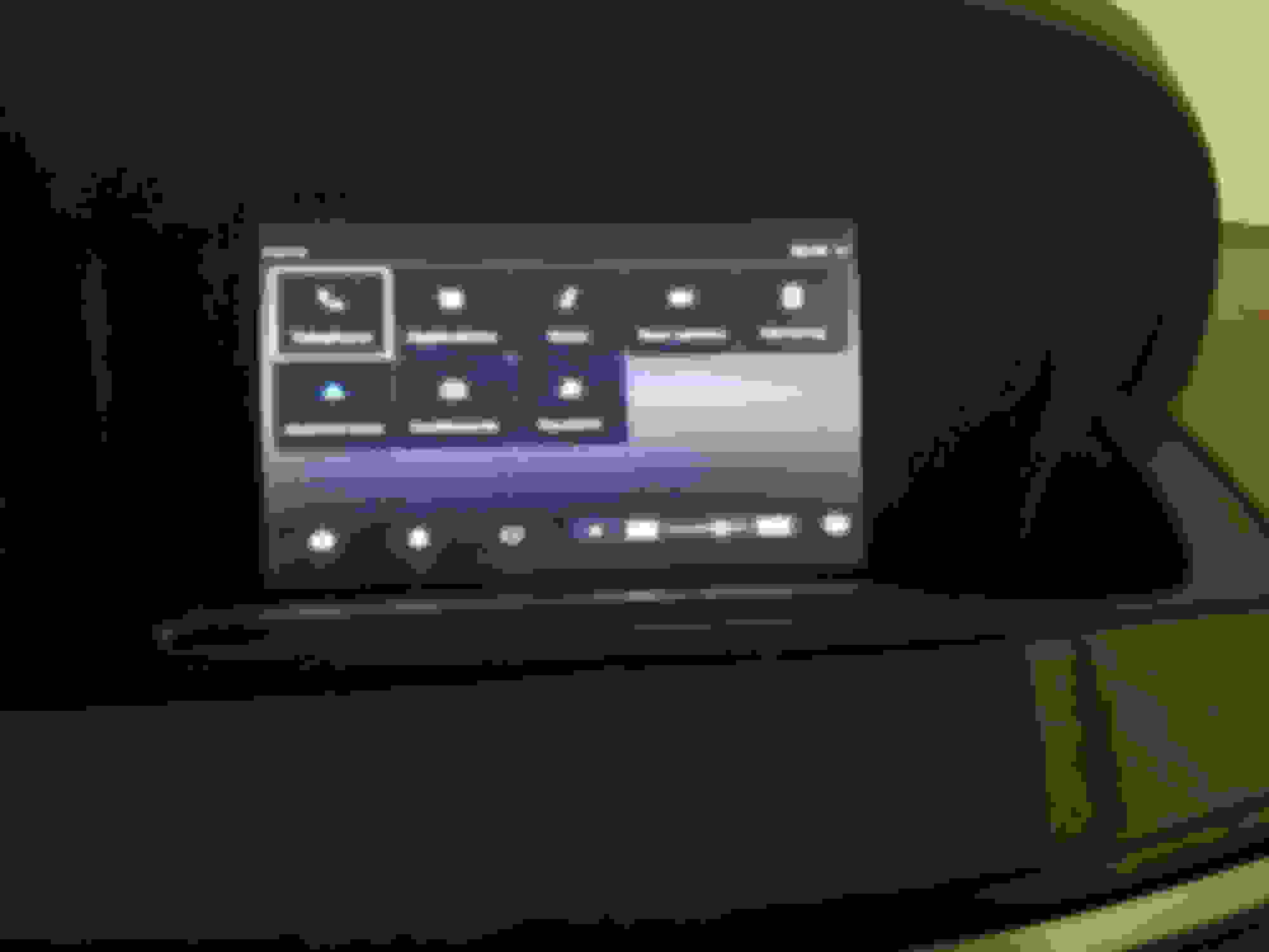
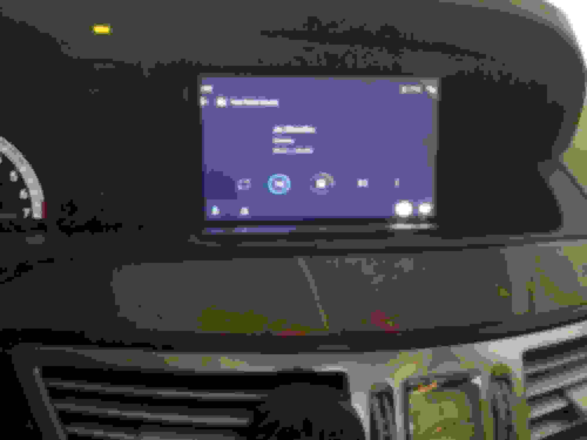
Here is some pictures of openauto (screen size for youtube music is now properly adjusted)
p.s hope my writing is not to bad, english isn't my language
Last edited by blackmambo90; Oct 12, 2020 at 11:34 AM.
Nice thread you have started, just in time when i started my project of integrating openauto to COMMAND 😊
I am doing some can bus filters now, i need two of them for two can bus networks. Its based on arduino + 2x mcp2515 for each.
Finished(almost) the first one yesterday. It allow you to have your "video in motion" enabled. Need only to figure out how to put arduino to sleep and wake it back up when can messages are present, otherwise it can draw your battery in a couple of days.
Niiiiiiiice,
are using 2 Arduinos and 2 x MCP2515 on each ( = 4 x MCP2515)?
About the power draw: why don't you simply draw the power for the Arduino(s) from switched power (you can "steal" it from the cigarette lighter)
Niiiiiiiice,
are using 2 Arduinos and 2 x MCP2515 on each ( = 4 x MCP2515)?
About the power draw: why don't you simply draw the power for the Arduino(s) from switched power (you can "steal" it from the cigarette lighter)
Thanks
And yes its 4 mcp2515 since each filter do connect in a splice to be able to filter like so:
COMMAND UNIT -> first mcp of filter and then the second mcp connect to the rest of the can bus network.
And for the switching power, this is actually how it is connected now, but i think it can lead to some canbus errors (not dangerous just some faults stored in module and i dont like that 😁 since arduino will take some time to power up, so the first messages will not pass trough
Nice project! Although it may be easier to just use an android headunit? Depending on which teensy you use power draw at sleep is much much lower than what you mentioned. Putting them to sleep can be a little finnicky but it works well once you get the hang of it. Though definitely use whatever you're comfortable with. There is no shortage of micrcontrollers thankfully.
Speaking of Android units...you guys realize that they handle the functions you are planning to use in this little project. Would be a shame if somebody extracted the app they use and got all the CAN frames from there, instead of messing with a can analyzer? Just saying. For people using the Android unit that could be triggered on every startup...so essentially park assist would be off after android boots up.
Last time when i bought android head unit for my w211, i spend so much time replacing bluetooth module and dsp in it to make it sound at least as nice as the original that it would be so much faster/cheaper to just create it from scratch. + i had to install aftermarket amplifier and wiring.
I guess now they are better than back then, but hey, i am not willing to spend ~1000$ for something that i am not sure will work and sound nice.
And in fact this project is very interesting to me and it work out well for now.
And i do agree that teensy can be put to sleep, but i haven't found any easy way of waking it up on canbus activity + only the canbus module for teensy(tja1051) will consume ~8ma and you cant put those one to sleep(at least that what is stated in datasheet) and you will have two of those module for each filter.....
Nice project! Although it may be easier to just use an android headunit? Depending on which teensy you use power draw at sleep is much much lower than what you mentioned. Putting them to sleep can be a little finnicky but it works well once you get the hang of it. Though definitely use whatever you're comfortable with. There is no shortage of micrcontrollers thankfully.
Speaking of Android units...you guys realize that they handle the functions you are planning to use in this little project. Would be a shame if somebody extracted the app they use and got all the CAN frames from there, instead of messing with a can analyzer? Just saying. For people using the Android unit that could be triggered on every startup...so essentially park assist would be off after android boots up.
You are probably right, but where's the fun in that ;-)
Nice project! Although it may be easier to just use an android headunit? Depending on which teensy you use power draw at sleep is much much lower than what you mentioned. Putting them to sleep can be a little finnicky but it works well once you get the hang of it. Though definitely use whatever you're comfortable with. There is no shortage of micrcontrollers thankfully.
Speaking of Android units...you guys realize that they handle the functions you are planning to use in this little project. Would be a shame if somebody extracted the app they use and got all the CAN frames from there, instead of messing with a can analyzer? Just saying. For people using the Android unit that could be triggered on every startup...so essentially park assist would be off after android boots up.
I'm absolutely certain it would be well within the capabilities of an Android replacement head unit, especially the one that replaces the little panel with soft buttons for chassis height, PA on/off, etc. It would probably be trivially simple, assuming one had access to the source code used to manage those soft buttons.
Two issues... first, I don't have any plans to dump several hundred bucks into an Android system shipped from somewhere in China, that may or may not work the way I like, and if it doesn't -- well, tough nuggets, you bought it. I'd maybe feel differently if there were one I could actually see and use to try out before making the purchase decision, but I think the chances of ever physically crossing paths with a W221 with one installed are close to zero. I live in Omaha, remember...
Second, while I've done a fair amount of firmware for microcontrollers -- I have thousands and thousands of lines of C code for PICs in various projects and products I've developed over the years -- at no time, ever, have I considered myself a programmer. I have no clue how to develop Android apps, to be honest. I'm willing to learn how to use CANbus because I can see a lot of potential future benefit for me. A lot of the avionics systems I work with in experimental aircraft use CANbus now, as does every car I'm likely to own as a DD before I die. Android -- I can take it or leave it, I don't have any deep desire to invest a lot of time learning how to develop and test Android apps. Just me.
Mercedes SLR McLaren 722 S Is Extremely Rare Example Modified by McLaren
Slideshow: A one-of-one U.S.-spec Mercedes-Benz SLR McLaren Roadster became even rarer after a factory-backed transformation at McLaren's headquarters.


 00.19-U-2160SAA Central CAN MODEL 221


 . It does canbus/linbus and good ol fashioned wires all from an android headunit via bluetooth...meaning you can put messages on the canbus or linbus at will...so for example you can integrate the fragrance atomizer from the 222. Smells nice.


 since arduino will take some time to power up, so the first messages will not pass trough


