When you click on links to various merchants on this site and make a purchase, this can result in this site earning a commission. Affiliate programs and affiliations include, but are not limited to, the eBay Partner Network.
This thread is home to my attempt to reverse engineer the COMAND 2.5 Firmware.
The MY 2001 software update stores the binaries unencrypted and with symbols so I think there is a high chance that the flash/eeproms will just contain the raw binary firmware.
For those who don't know, the COMAND 2.5D is devided into to devices, the radio/tv/tape/telephone and the navigation system. Both devices use different bioses/firmwares.
I'll refer to the RTTT and NAV bios from now on.
Why do I want to reverse engineer the COMAND 2.5D's firmware?
It's fun, so why not?
To finally understand the DX navigation cd structure
To create custom up-to-date maps for the system
What do I know at this point:
The MY01 update CD stores the firmware delta (I assume) for the flash/eeprom chip in a file.
I'm not sure if the disc also stores the navigation system's firmware, but several users have said that they could look up an address by ZIP code after applying this update
ODEM0718.DNL
One of the (I suspect many) processors inside the device is the Renesas V850E2M.
All the .EXE ELF files (either on the update disc or on the navigation disc) contain the V8xx header. This CPU is recognized by all the decompilation tools I tried.
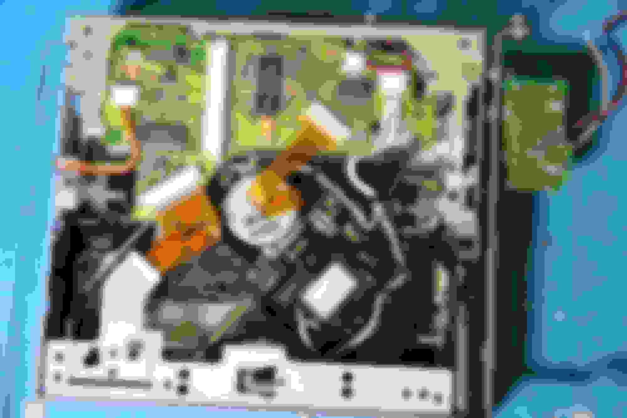
Opening the COMAND 2.5
In order to seperate the NAVand RTTT systems, you'll need to undo these screws, on both sides
Seperating NAV from RTTT
To seperate the RTTT from the screen, remove the screws on both sides of the unit and remove the top lid. Use a flat head to carefully pry it loose
Seperating RTTT
To remove the screen, unscrew these screws and remove the ribbon cables Screen removal
Screen removal frontpanel
Disconnecting screen cables
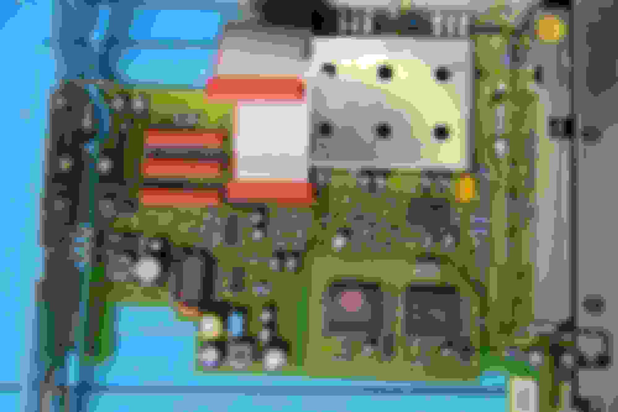
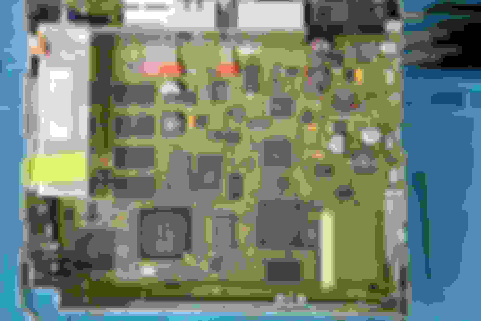
Removing the PCB's
Unscew all the screws at these levels on both sides
Then unscew and remove the cover of the RF connector and disconnect the screw of next to the D2B interface.
RF and D2B
After removing the 3 connectors, you should be able to seperate the first PCB from the rest. Make sure to be very gentle with the connector and PCB.
Power and data
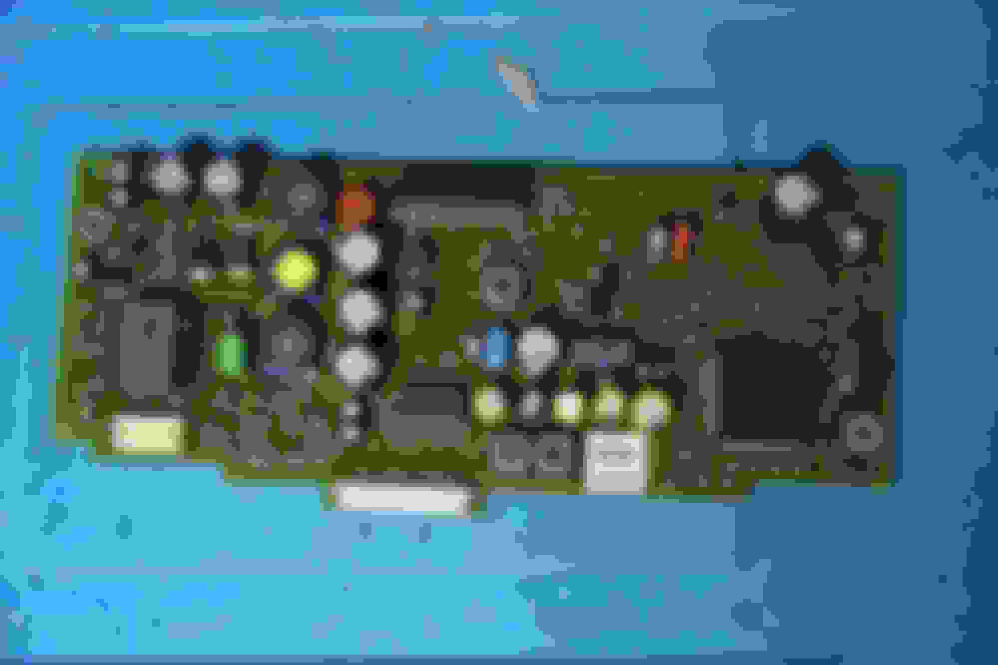
To remove the PCB tray in between the last two PCB's, unscrew the following screws
Remove the power supply PCB. Be very careful with this! The board can break very easily and the pins can damaged too.
That should reveal the last PCB in the RTTT unit, when you do want to inspect the last PCB's bottom, please remove the bottom of the COMAND unit itself. It will pop right off, you are not able to remove the PCB from the housing unless you desolder it.
NAV Unit
To remove the CD reader from the NAV unit, remove these screws
Remove these screws and the ribbon cable
And the CD reader should lift out and put it on top of the NAV unit. BE CAREFUL since we haven't disconnected everything yet.
Disconnect the final cable and the CD reader is out
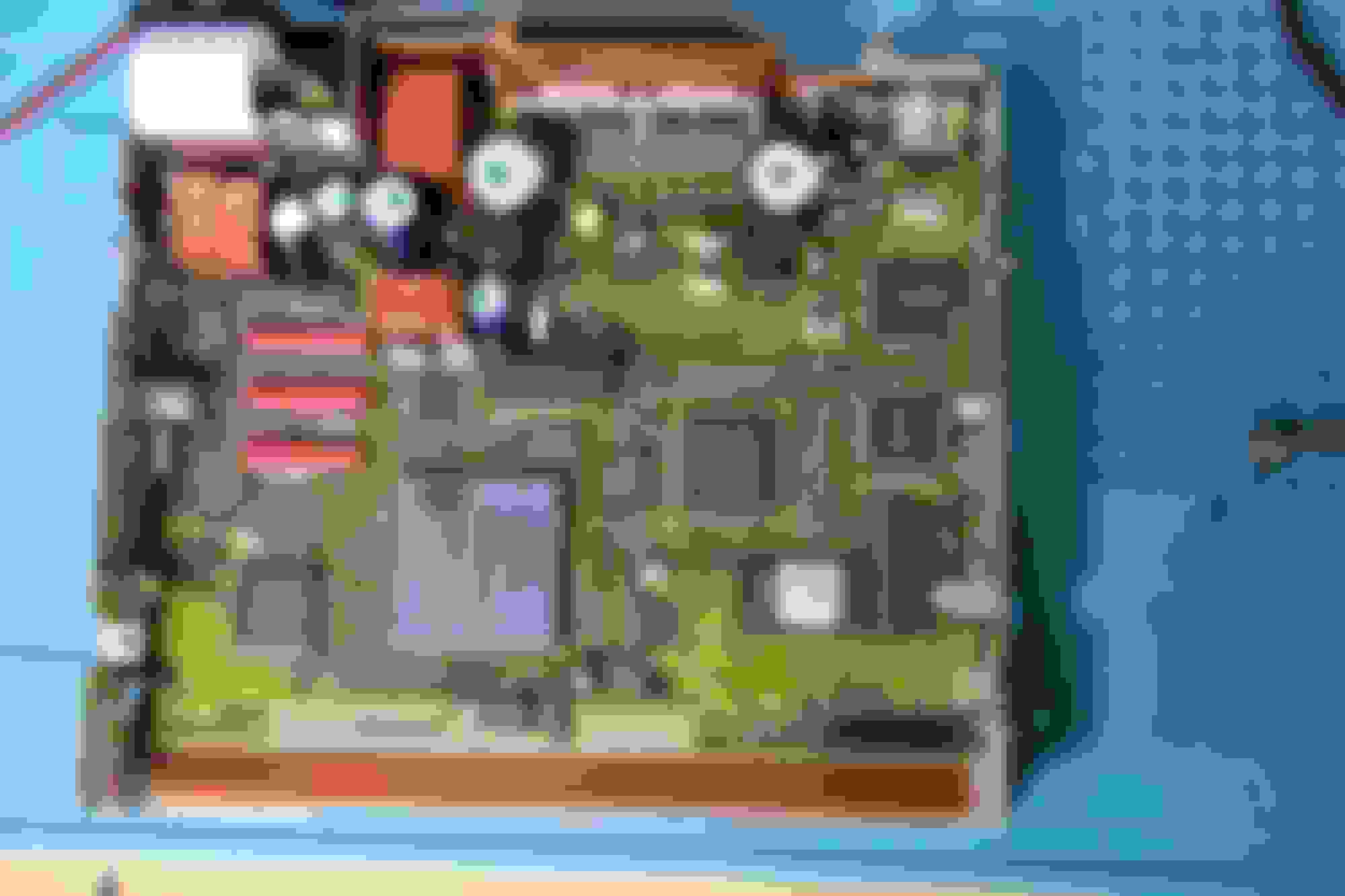
It's strange because most of the traces of this chip go to the BoschHD6437034E13F chip
I can find references to this chip in the firmware files present on the update disc MY-01 (MY01.zip)
I found firmwares of the Skoda MFD2, which also uses TravelPilot DX discs and in there are references to this chip too. I think it's safe to assume that all of those systems are basically the same system, but have different user-interfaces
It's strange because most of the traces of this chip go to the BoschHD6437034E13F chip
I can find references to this chip in the firmware files present on the update disc MY-01 (Attachment 434393)
I found firmwares of the Skoda MFD2, which also uses TravelPilot DX discs and in there are references to this chip too. I think it's safe to assume that all of those systems are basically the same system, but have different user-interfaces
I loop mounted the ISO and loaded the bin into a hex editor. Not sure what there is to reverse engineer. It's a 2002 Navigation system firmware update for a 2001 vehicle. If you had a few bin files you could diff them to locate where values are stored within the file, though. Then you could, say, change default settings and flash the file back... before resoldering it back onto the board. Sounds like a lot of work for an old car to me though.
2025 Maserati Grecale Folgore and 2024 Jaguar F-PACE SVR
I guess you could try a disassembler on the executable or its libraries. That might give you the names of some functions the update program uses. But without knowing what software they used to create it going any further sounds like a pain. I'd personally just stick with working with the flash chip. Take a before and after image and diff them. If you know something specific that changed, search for those values in the diff areas and tada, you can now modify that value to what you want instead of what they want.
I'm not as familiar with all the hardware as you but I've used stuff like this in the past to avoid desoldering and resoldering (lol, spell checker says those arent real words):
2025 Maserati Grecale Folgore and 2024 Jaguar F-PACE SVR
I mean, the tools never get updated past chip obsolescence so it'll likely end up being an exercise in running old OS version in a VM with USB pass-through. Just as an example that really has nothing to do with this, I recall trying to get VADIS running so I could **** with my 2003 Volvo S80. It's even a Windows app so how hard could it be? Well, when it was written fully integrating Internet Exploder, er, Explorer into the OS was still a major focus at Microsloth. And VADIS relies on IE DLLs to run... so TL;DR version: I ended up having to run Windows Vista inside VirtualBox on my Linux PC and that's was just to get STARTED fookin' around with it.
I mean, the tools never get updated past chip obsolescence so it'll likely end up being an exercise in running old OS version in a VM with USB pass-through. Just as an example that really has nothing to do with this, I recall trying to get VADIS running so I could **** with my 2003 Volvo S80. It's even a Windows app so how hard could it be? Well, when it was written fully integrating Internet Exploder, er, Explorer into the OS was still a major focus at Microsloth. And VADIS relies on IE DLLs to run... so TL;DR version: I ended up having to run Windows Vista inside VirtualBox on my Linux PC and that's was just to get STARTED fookin' around with it.
Any updates to this? W215 here and I've been trying to dig around on it because there are some minor differences on the W215 COMAND 2.5 than listed for others that I had found, but I have had no progress other than some update CD files' assembly code showing up and some not. Nothing interesting.
EDIT: I ran Ghidra, and I exported the Ghidra Zip Files. I didn't realize on Ghidra it exports as 2 different programs? Here is the first, and here is the second. They seem to be different but both were extracted from the MY01 Update Disc COMP_DL.EXE file. Is this useful to anyone?
Last edited by GabeS06; May 31, 2024 at 02:49 AM.
Reason: Ghidra
Mercedes SLR McLaren 722 S Is Extremely Rare Example Modified by McLaren
Slideshow: A one-of-one U.S.-spec Mercedes-Benz SLR McLaren Roadster became even rarer after a factory-backed transformation at McLaren's headquarters.